Antique Keyhole-Inspired Triband Textile Antenna for Sub-6 GHz 5G Bands(N40, N47 and N79)
Abstract
This paper presents a Flexible Multiband Textile Antenna (FMTA) for wearable Sub-6 GHz applications, inspired by an antique keyhole design and fabricated on a denim substrate with a dielectric constant of 1.7. A rectangular slot and Defected Ground Structure (DGS) are incorporated to achieve triple-band operation covering the 3GPP-standard-compliant n40 (2.3 GHz), n79 (4.5 GHz), and n47 (5.9 GHz) bands. The proposed antenna provides an 860 MHz impedance bandwidth in the n79 band, exceeding the 3GPP requirement of 600 MHz and demonstrating enhanced wideband performance. These operating bands support high-capacity 5G communications and Vehicle-to-Everything (V2X) applications in intelligent transportation systems. The antenna exhibits stable radiation characteristics, good impedance matching, and satisfactory gain under both flat and bent conditions. Furthermore, the maximum Specific Absorption Rate (SAR) is 0.799 W/kg, which is well below the recommended safety limits, confirming its suitability for wearable applications. The fabricated prototype shows good agreement with the simulated results, validating the effectiveness of the proposed design.
Index Terms
Flexible antenna; Multi band antenna; Slot antenna; Vehicle to Vehicle (V2V) communication.
I. INTRODUCTION
Vehicular communication is the backbone of intelligent transportation systems (ITS) and smart city infrastructure [1]-[2]. This Vehicle-to-Everything (V2X) communication enhances both safety and traffic efficiency of connected and autonomous vehicles [3]-[5]. The initial version of V2X was developed for localized vehicular messaging [6]-[9] and the Internet of Vehicles (IoV) [10], which relied on IEEE 802.11-based standards. It was referred to as Dedicated Short-Range Communication (DSRC) or Wireless Access in Vehicular Environments (WAVE). The U.S. Federal Communications Commission (FCC) allocated 75 MHz of spectrum within the 5.9 GHz band specifically for DSRC-based systems [11]. Over time, DSRC could not fully meet the requirements of advanced vehicular communication systems such as low latency, long range, and scalability. In recognition of this need, the 3rd Generation Partnership Project (3GPP) introduced Cellular V2X (C-V2X) in Release 14 (Rel-14), which defines communication paradigms for Vehicle-to-Vehicle (V2V), Vehicle-to-Infrastructure (V2I), and Vehicle-to-Pedestrian (V2P) using the LTE and 5G cellular networks [1], [12]. In the context of a high-throughput vehicular system, an antenna with a compact form factor and multiple operating bands [2] is required. Generally, multiband antennas support diverse applications by allowing a single structure to resonate across various frequency bands.
A dual-band patch antenna with a rectangular slot was developed to operate at 5.9 GHz (DSRC) and 28 GHz (mmWave) [13]. A cross-slot antenna was developed to operate at 2.4, 4.7, 5.3, and 5.9 GHz for ITS [14], supporting various WiFi and ITS functions. A miniaturized multiband PIFA antenna was developed using integrated slots and stubs to cover LTE Band 40 (2.3 GHz), 5G Band n79 (4.5 GHz), and DSRC [2]. Hexagonal patch with an elliptical slot and Defective Ground Structure (DGS) is reported for DSRC and C-V2X [15] applications. To support LTE and 5G bands used in V2X systems, an E-shaped microstrip antenna embedded with a Split Ring Resonator achieved tri-band resonance at 1.8, 3.6, 4.5, and 5.7 GHz [16]. Another attempt to obtain a wide bandwidth suitable for V2I applications involved stacking a patch antenna originally designed for WLAN [17] and demonstrating it through slotting and stub-loading techniques for mmWave automotive radars [18]. A multiband circular textile antenna operating in WiFi and WiMAX bands was proposed with dual-slot geometry [19]. Additionally, a dual-band MIMO antenna that resonated at 4.54 GHz and 5.8 GHz was also investigated for vehicles where diversity and redundancy are very important [20]. The authors found that a compact 2.4 GHz/3.5 GHz dual-band architecture should work well for DSRC, WiFi, and sub-6 GHz 5G systems in cars [21].
There is a significant amount of research on individual V2X bands and interfaces, but relatively little on integrated multi-band deployments that utilize n40 and n79 for Uu-based network services and n47 for PC5 direct connection simultaneously. This paper explores the role of three important 5G bands: n40 (2.3 GHz band), n79 (4.5 GHz band), and n47 (5.9 GHz band) in enabling multi-functional V2X capabilities. An overview of V2P Communication supporting these n40, n47, and n79 bands is shown in Fig. 1.

Schematic of V2P Communication supporting n40 (2.3 GHz band), n79 (4.5 GHz band), and n47 (5.9 GHz band)
Band n47 enables direct V2V, V2I, and V2P communication through PC5 interface [4] with ultra-reliable, low-latency transmission. In contrast, bands n40 and n79 support network-based V2X communication through the Uu interface. This enables cloud-based services, including infotainment, remote diagnostics, pedestrian tracking, and augmented reality warnings. This paper provides a comprehensive overview of combining these bands in vehicle systems. It focuses on their connections, compromises, and possible deployment strategies suited to diverse urban mobility settings.
A. Contributions
The main contributions of this work are as follows:
-
• In this work, the authors developed a compact multiband antenna for 5G New Radio (NR) applications. It specifically targets the N40, N79, and N47 frequency bands. The antenna showed resonant frequencies at 2.35 GHz, 4.70 GHz, and 5.89 GHz, closely matching the specified bands of 2.3 to 2.4 GHz, 4.4 to 5.0 GHz, and 5.855 to 5.925 GHz.
-
• The novelty of this design is its ability to provide bandwidths as per the 3GPP standard.
-
• Additionally, the antenna had consistent gain levels ranging from 3.14 to 3.8 dBi and respectable radiation efficiencies between 69.1% and 77.9%. This supports reliable signal transmission and reception.
-
• This contribution supports the design of compact, efficient multiband antennas. These antennas support multiple 5G NR bands while providing good gain and bandwidth.
The paper is organized as follows: Section 2 explains the configuration and design procedure of the tri-band antenna with enhanced bandwidth. Simulated results and the effect of various structural parameters are analyzed in Section 3. Section 4 describes the fabrication, measurement, and comparison of the proposed antenna with other multi-band antennas. Finally, Section 5 concludes the paper.
II. ANTENNA DESIGN DESCRIPTION
The rectangle and circle are commonly used shapes because of their less complicated analysis and ease in fabrication. The resonance frequency equations for rectangular and circular patches are defined in [22].
For the rectangular patch, the width (W) and length (L) of the patch are calculated using equations (1), (2), & (3) [3].
where fr is resonance frequency, εr is relative permittivity, εeff is effective permittivity, ε0 and μ0 are free space permittivity and permeability, h is the thickness of the substrate.
The proposed Flexible Multiband Textile Antenna (FMTA) is designed on a flexible textile substrate, with a dielectric constant (ɛr) of 1.7 and substrate thickness (h) of 1 mm, chosen for its suitability in wearable vehicular communication systems. The radiating patch, dimensioned 48 mm × 60 mm (L × W), is mounted on the substrate's top surface. Table 1 lists all structural parameters. The antenna is fed using a microstrip line designed for 50 Ω impedance matching. The proposed antenna geometry is inspired by the shape of a traditional antique keyhole. For visual reference, Fig. 2 (a) shows an illustration of a representative antique keyhole. The keyhole-inspired geometry was adapted to achieve the desired current distribution and compact multiband performance. The proposed structure is achieved by systematically following stages 1 to 4 as shown in Fig. 2 (b).

(a) Antique keyhole structure used as the design inspiration and (b) Schematic view of FMTA operating at 2.3GHz, 4.5GHz and 5.9GHz
III. SIMULATED RESULTS AND PARAMETRIC ANALYSIS
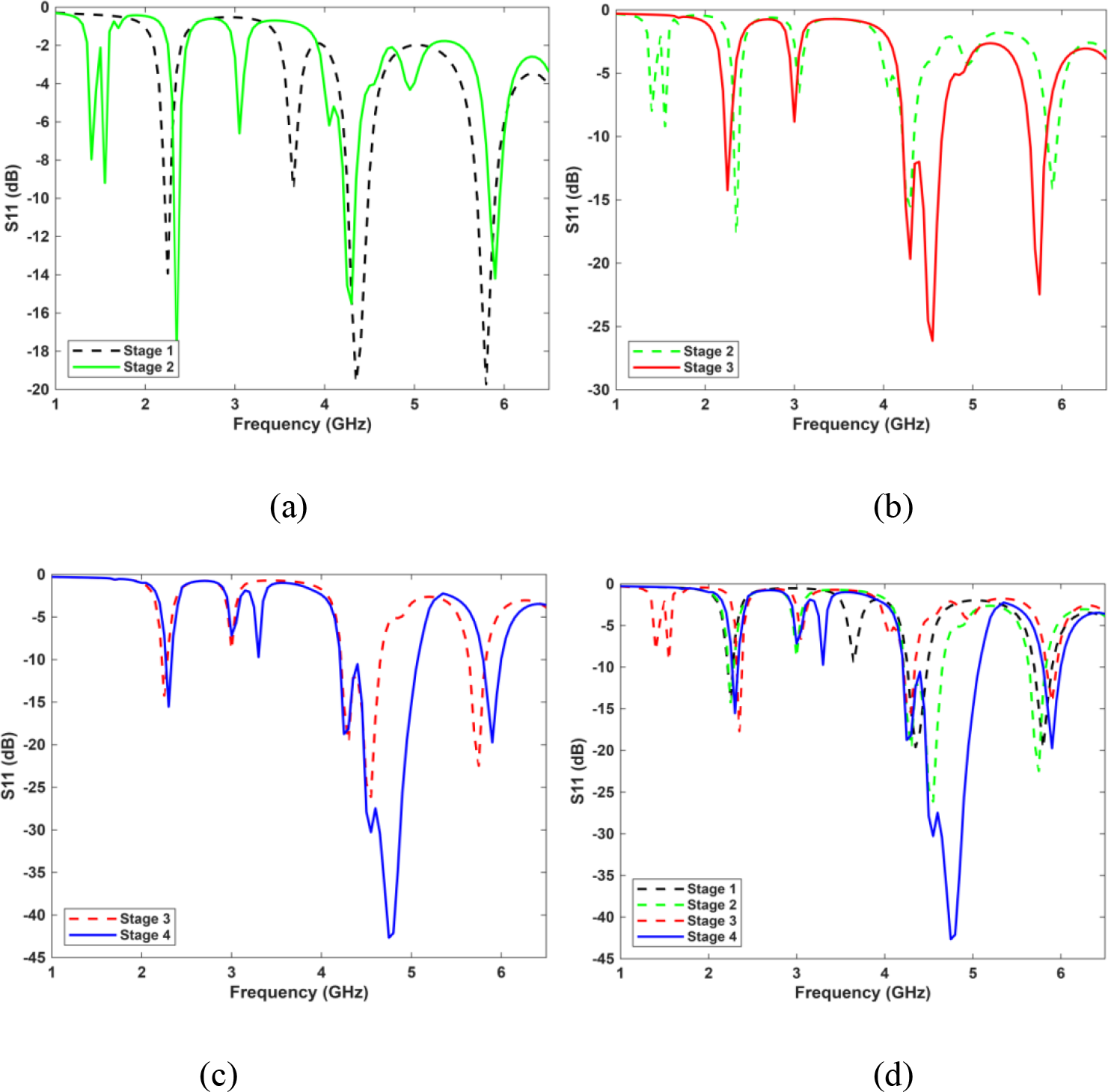
The proposed antenna is designed and optimized using HFSS. Simulations are carried out using the time-domain solver, with open (add space) boundary conditions to emulate free-space radiation. The antenna has been excited through a 50-Ω discrete/waveguide port connected to the microstrip feed. Adaptive mesh refinement is employed until convergence is achieved, ensuring accurate prediction of the reflection coefficient and radiation characteristics. Fig. 3 presents the simulated reflection coefficient (S11) comparison of the proposed antenna in each stage. The change from Stage 1 to Stage 2 shows the first improvement made by the vertical slot next to the non-radiating edge. The change from Stage 2 to Stage 3 shows the second improvement made by the second step. Similarly, the variation between Stage 3 and Stage 4 captures the improvement achieved through the DGS. When all stages are viewed together, the cumulative effect becomes evident, confirming that each incremental change systematically contributes to improved impedance matching and broader bandwidth, ultimately leading to the desired ultra-wideband performance. As shown in Fig. 3(a), in stage 1, the rectangular patch resonates at 2.25 GHz, 4.35 GHz, and 5.8 GHz, with a better reflection coefficient (< 10 dB) and operating bands of 2.22-2.27 GHz, 4.26-4.48 GHz, and 5.7-5.9 GHz. Variation in reflection coefficient at each stage is compared between stages 1 and 2, stages 2 and 3, and stages 3 and 4.

Comparison of the simulated reflection coefficient of proposed antenna at stage (a) 1, 2 (b) 2, 3 (c) 3, 4 and (d) all stage
To obtain the specified bandwidth and resonance related to sub-6 GHz vehicular communication bands n40, n47, and n79, a rectangular slot parallel to the non-radiating edge is added, introducing an additional resonant mode around the n79 band as shown in Fig. 3(b). To further improve the current path diversity, two L-shaped arms are incorporated at the top and bottom edges of the patch. Fig. 3(c) shows the comparison of the reflection coefficient produced in stages 2 and 3. The L-shaped arms shift the lower-band resonance from 2.4 to 2.35 GHz, the mid-band resonance from 4.3 to 4.55 GHz, and the upper-band resonance from 6 to 5.75 GHz. It is evident that slits with a patch introduce additional resonance. Finally, as shown in Fig. 3(d), in stage 4, an L-shaped DGS is incorporated to suppress unwanted surface currents and alter resonant behavior, thereby improving bandwidth and reflection-coefficient characteristics in the n40, n47, and n79 (4.5 GHz) bands. It is also observed that the slot introduced in DGS should be optimized to be close to the existing resonance to widen the bandwidth. Table II lists a detailed comparison of the proposed FMTA's functional parameters.
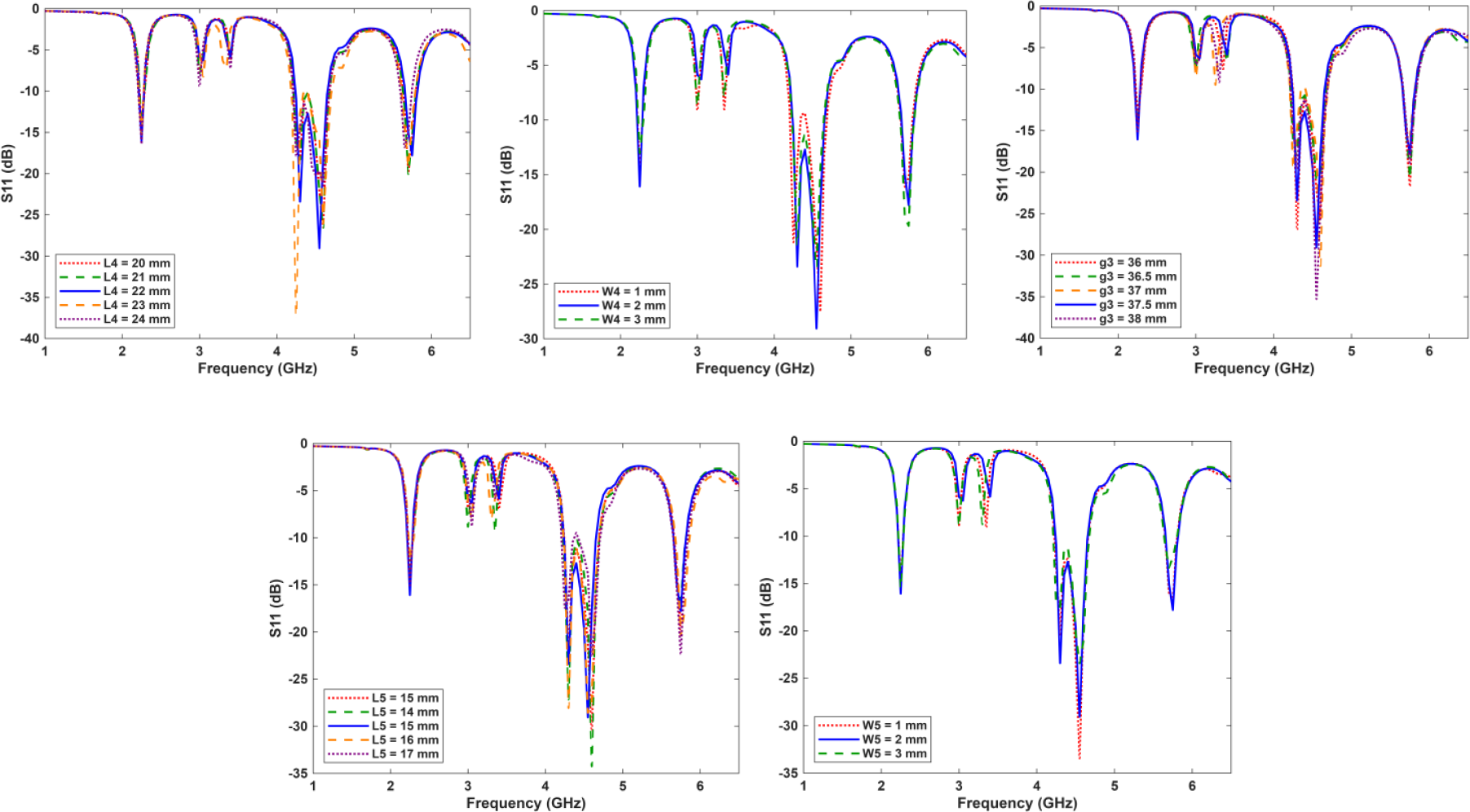
Final design at stage 4 is obtained by performing parametric analysis. For parametric analysis, the significant antenna structural parameters L1, W1, g1, L2, W2, L3, W3, g2, L4, W4, L5, W5 and g3 are varied. The effect of these parameters is shown in Fig. 4, Fig. 5, and Fig. 6 respectively. As evident from Fig. 4, variation in the structural parameters affects the resonance, bandwidth. Parameters L1, W1 and g1 which are associated in stage 2, are varied from 28 to 32mm, 1 to 3mm and 8 to 12 mm, respectively.


As shown in Fig. 4, the variation of L1 (28-32 mm) significantly influences the resonance positions, particularly around 3 GHz and 4 GHz. Increasing the slot length shifts the resonances toward lower frequencies, consistent with the effective electrical lengthening of the current path. The effect of W1 (1-3 mm) illustrates; wider slots improve impedance matching at lower frequencies but introduce mismatch at higher bands. This behaviour is attributed to the change in coupling between the patch and ground. The influence of g1 (8-12 mm), governs the feed coupling strength. A smaller gap enhances coupling but may cause impedance mismatch beyond 4 GHz, while a larger gap reduces coupling, degrading reflection coefficient at lower frequencies.
Overall, the parametric study confirms the optimized dimensions (L1 = 30 mm, W1 = 2 mm, g1 = 10 mm). Similarly, the size and position of L arms attached to the radiating element are analyzed in Fig. 5. The optimized parameters (L2 = 22 mm, W2 = 2 mm, g2 = 37 mm) yield the most stable impedance response and shift the resonance from 2.4 to 2.25 GHz and 6 to 5.75 GHz, with improved bandwidth. Finally, the influence of DGS size and location is analyzed and shown in Fig. 6.
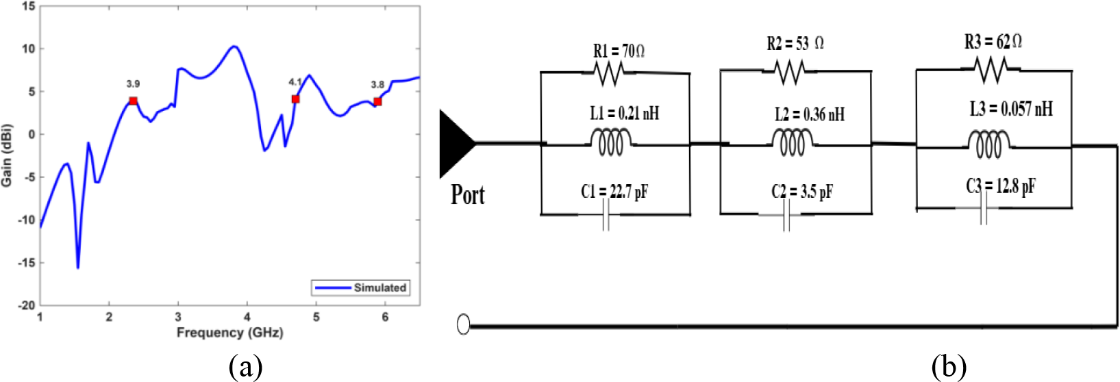
The gain of the single antenna exceeds 3 dBi across each operating frequency. At 2.35 GHz, 4.7 GHz and 5.89 GHz, the gain is observed to be 3.9 dBi, 4.1 dBi and 3.8 dBi, respectively. Fig. 7 (a) shows the gain plots for each operating frequency. Due to the notch, inductance and capacitance will be developed, and they are represented as a parallel combination of L and C. Hence, the permittivity (ε) and permeability (μ) of the conventional patch are altered, leading to changes in resistance (R), capacitance (C), and inductance (L). Thus, the equivalent circuit of the proposed antenna can be considered as a parallel combination of impedance and the truncated patch as shown in Fig. 7(b). Therefore, the overall input impedance of the proposed antenna can be calculated as [22].

The reflection coefficient of the proposed antenna is given as [22]
where Zp is the total impedance of the patch with notches, Zg is the impedance of L-shaped DGS and Z0 is the characteristic impedance of the feed (50 ohms). The equivalent circuit parameters are determined from the resonant characteristics observed in the full-wave electromagnetic simulation. Initially, the resonant frequencies and impedance behavior corresponding to the three operating bands were identified from the simulated S11 response. Based on standard RLC resonator relationships, preliminary values of resistance, inductance, and capacitance were estimated. Subsequently, the lumped-element values were iteratively refined through parameter tuning to closely match the reflection-coefficient response of the equivalent circuit to that of the proposed antenna. The final values of the R, L, C elements are selected as listed in Table III, when the equivalent circuit accurately reproduced the resonance frequencies and impedance matching characteristics observed in the electromagnetic simulation.
In practical wearable scenarios, textile antennas are subject to bending and conformal placement on the human body, which directly influences current distribution, resonance stability, and impedance bandwidth. The reflection coefficient performance of the proposed FMTA under different bending conditions with radii of 30 mm, 60 mm, 90 mm, and 120 mm, compared to the flat state is shown in Fig. 8. The results indicate that the antenna maintains stable resonant frequencies at 2.35 GHz, 4.7 GHz, and 5.89 GHz across all bending radii, with only minor shifts in frequency and negligible degradation in reflection coefficient. This demonstrates that the antenna’s impedance matching and multiband characteristics are largely unaffected by mechanical deformation, confirming its suitability for conformal and wearable applications.

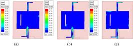
The simulated surface current distribution of the FMTA at three operating frequencies is shown in Figs. 9(a), 9(b) and 9(c). It is found that at 2.3 GHz band, the current is predominantly concentrated along the feedline and lower edges of the patch, indicating fundamental mode excitation. At 4.5 GHz band, strong current concentrations appear around the slot and the defected ground structure, confirming their role in generating the mid-band resonance. At 5.9 GHz band, the current is more localized near the edges and corners of both the patch and the slot, signifying higher-order mode excitation. These distributions validate that different structural elements of the antenna are responsible for the respective resonances, enabling effective multiband operation.
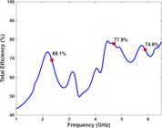
Radiation efficiency is an important performance measure for wearable and communication antennas because it directly affects connection dependability and system throughput. A radiation efficiency of at least 60% is usually the minimum acceptable level for practical use, as it ensures enough radiated power despite ohmic and dielectric losses. Fig. 10 shows the radiation efficiency: 69.1% at 2.35 GHz, 77.9% at 4.7 GHz, and 74.6% at 5.89 GHz. As mentioned, the DSRC band ranges from 5.85 to 5.925 GHz for V2V communication. Similarly, our measured and simulated bandwidth, with 74.6% efficiency, ranges from 5.855 to 5.925 GHz, which falls within the n47 band. Table IV lists the functional parameters of the proposed FMTA at the three frequencies.
IV. ANTENNA FABRICATION AND MEASUREMENT OF RESULTS
The proposed antenna supports multi-band operation for 5G New Radio (NR) applications, specifically targeting the N40 (TD 2300), N79 (TD 4500), and N47 (TD 5900) bands. The prototype is fabricated using a denim textile substrate. The radiating patch and ground plane were cut from conductive copper foil and carefully attached to the substrate using adhesive bonding to ensure intimate contact and dimensional stability. An SMA connector has been soldered to the feed line to facilitate experimental characterization using a vector network analyzer. The proposed FMTA is fabricated, and its front and back view is shown in Fig. 11(a).

(a) Prototype view, (b) comparison of reflection coefficient and (c) comparison of gain of proposed FMTA
Comparison of the reflection coefficient under flat condition and bending at 20 mm is shown inFig. 11 (b). The reflection coefficient shows slight variation between the measured and simulated values. The measured resonances occurred at 2.35 GHz, 4.70 GHz, and 5.89 GHz, with corresponding reflection coefficient values of -15.25 dB, -27.18 dB, and -15.47 dB, respectively, as shown in Fig. 11 (b).
The antenna exhibits gains of 3.9 dBi, 4.1 dBi, and 3.8 dBi, enabled by the optimized radiating structure that supports distinct current paths for each band. This ensures discrete yet overlapping operational ranges suitable for modern 5G wireless communication systems. Fig. 11 (c) compares the simulated and measured gain values.
E plane and H plane radiation patterns at 2.3GHz, 4.5GHz and 5.9GHz is shown in Fig. 12 (a), 12 (b) and 12 (c) respectively. Fig. 12 (a) illustrates the simulated and measured radiation patterns of the proposed antenna at 2.3 GHz. The H-plane demonstrates nearly omnidirectional radiation, while the E-plane exhibits a dipole-like shape. The measured results agree well with the simulations, confirming reliable operation in the lower IoT/LPWAN band with a peak gain of 3 dBi. Fig. 12 (b) shows the radiation characteristics at 4.5 GHz. The antenna displays more directional radiation patterns with well-defined main lobes in both planes, suitable for mid-band 5G applications. The measured peak gain of 4 dBi validates stable performance, with good agreement between simulations and measurements. Fig. 12 (c) presents the radiation behavior at 5.9 GHz, where higher-order modes introduce multiple side lobes in both the E- and H-planes. Despite these effects, the antenna achieves a peak gain of 5 dBi and maintains consistency between simulated and measured patterns, making it suitable for upper sub-6 GHz 5G services.

As shown in Fig. 13(a), the SAR is highest at 2.30 GHz (0.799 W/kg) due to deeper tissue penetration at lower frequencies. It decreases to 4.50 GHz (0.140 W/kg), as shown in Fig. 13(b), and reaches a minimum at 5.90 GHz (0.060 W/kg), as shown in Fig. 13(c), because higher frequencies have shallower penetration and lower energy absorption. All values are within permissible safety limits, making the antenna suitable for body-centric applications.

Table V lists the performance of the proposed antenna alongside previously reported work. The dual-band antenna reported in [21] exhibits resonances at 2.4 GHz and 3.5 GHz with moderate gains of 1.6 dBi and 6 dBi, but limited bandwidth performance. The five-band configuration presented in [17] offers wide frequency coverage from 0.92 GHz to 5.46 GHz; however, the reported gains and bandwidths are inconsistent across the bands. The antennas described in [23] and [24] achieve triple-band operation suitable for WLAN and WiMAX applications, but the gain remains below 3 dBi and the efficiency is not reported. The design in [25] provides comparable gain values but with narrower bandwidths, while [26] demonstrates higher radiation efficiency exceeding 80%, albeit with reduced gain. The multiband antenna in [27] shows very wide impedance bandwidths but suffers from poor radiation efficiency at certain frequencies. In contrast, the proposed antenna achieves three well-defined resonances at 2.35 GHz, 4.64 GHz, and 5.89 GHz with consistent gain above 3 dBi, relative bandwidth up to 18.53%, and radiation efficiency exceeding 70%, thereby offering a superior balance between bandwidth, gain, and efficiency for wearable sub-6 GHz 5G and IoT applications.
V. CONCLUSION
The proposed Flexible Multiband Textile Antenna (FMTA), fabricated on a low-permittivity jeans substrate (ɛr = 1.7), successfully operates in three distinct sub-6 GHz 5G NR bands N40 (2.35 GHz), N79 (4.70 GHz), and N47 (5.89 GHz). The measured reflection coefficients of -15.53 dB, -30.27 dB, and -19.27 dB indicate good impedance matching across all bands. The obtained operational bandwidths of 100 MHz, 860 MHz, and 200 MHz not only meet but, for N79 and N47, exceed the corresponding 3GPP allocations, ensuring robust coverage and flexibility for various deployment scenarios. The antenna achieves gains of 3.9 dBi, 4.1 dBi, and 3.8 dBi with corresponding efficiencies of 69.1%, 77.9%, and 74.6%, making it suitable for high-capacity communications in urban environments and Vehicle-to-Everything (V2X) applications. Integrating a rectangular slot and Defected Ground Structure (DGS) enables the desired multiband performance while maintaining a compact, flexible profile. The combination of stable radiation characteristics, high efficiency, and mechanical flexibility makes the proposed FMTA a promising candidate for wearable and vehicular communication systems in future smart transportation networks.
DATA AVAILABILITY STATEMENT
All data analyzed during this study are included in the article.
REFERENCES
-
[1] Abdul Rehman, Roberto Valentini , Elena Cinque , Piergiuseppe Di Marco, and Fortunato Santucci, “On the impact of multiple access interference in LTE-V2X and NR-V2X sidelink communications”, Sensors, vol.23, no.4901, pp.1-17, 2023. https://doi.org/10.3390/s23104901
» https://doi.org/10.3390/s23104901 - [2] Amruta A. Nikam and Rupali B. Patil, “design and development of multiband PIFA antenna for vehicular LTE/5G and V2X communication”, EURASIP Journal on Wireless Communications and Networking, vol. 104, pp. 1-15, 2023.
- [3] Miguel Sepulcre, Manuel Gonzalez-Martín, Javier Gozalvez, Rafael Molina-Masegosa, and Baldomero Coll Perales, “Analytical models of the performance of IEEE 802.11p vehicle to vehicle communications”, IEEE Transactions on Vehicular Technology, pp.1-12, 2021.
- [4] A. Hajisami, J. Lansford, A. Dingankar, and J. Misener, “A tutorial on the LTE-V2X direct communication”, IEEE Open Journal of Vehicular Technology, vol. 3, pp. 388-398, 2022.
- [5] Ehsan Moradi Pari, Danyang Tian, Mojtaba Bahramgiri, Samer Rajab, and Sue Bai, “DSRC versus LTE-V2X: empirical performance analysis of direct vehicular communication technologies”, IEEE Transactions on Intelligent Transportation Systems, vol. 24, no. 5, pp.1-15, 2023.
- [6] Z. Xu, X. Li, X. Zhao, M. H. Zhang, and Z. Wang, “DSRC versus 4GLTE for connected vehicle applications: a study on field experiments of vehicular communication performance”, Journal of Advanced Transportation, vol. 2017, pp. 1-10, 2017.
- [7] Nguyen, Hieu, and Yong Liang Guan. "DSRC performance under the adjacent channel interference of cellular-based V2X at 5.9 GHz band", 2024 IEEE 99th Vehicular Technology Conference (VTC2024-Spring), pp. 1-5. 2024.
-
[8] Alessandro Bazzi, O. Antoine, Berthet, Claudia Campolo, Barbara Mavì Masini, Antonella Molinaro, and Alberto Zanella, “On the design of sidelink for cellular V2X: a literature review and outlook for future”, IEEE Access, vol.4, pp. 1-28, 2021. DOI. 10.1109/ACCESS.2021.3094161
» https://doi.org/10.1109/ACCESS.2021.3094161 - [9] Qureshi, Imran Ali, and Sohail Asghar, "A systematic review of the IEEE-802.11 standard’s enhancements and limitations," Wireless Personal Communications, vol. 131, no. 4, pp. 2539-2572, 2023.
-
[10] Shanzheng Xue, Siyuan Gong and Xinyi Li, “Comparative study of IEEE 802.11bd and IEEE 802.11p on the data dissemination properties in dynamic traffic scenarios”, Applied Science, vol.14, no. 2099, pp.1-21, 2024. https://doi.org/10.3390/app14052099
» https://doi.org/10.3390/app14052099 -
[11] Mario H. Castañeda Garcia, Alejandro Molina-Galan, Mate Boban, Javier Gozalvez, Baldomero Coll-Perales, Taylan Şahin and Apostolos Kousaridas, “A Tutorial on 5G NR V2X Communications”, IEEE Communications Surveys & Tutorials journal, vol.23, no.3, pp.1-55, 2021. DOI 10.1109/COMST.2021.3057017
» https://doi.org/10.1109/COMST.2021.3057017 - [12] Muhammad Jalal Khan, Manzoor Ahmed Khan, Sumbal Malik, Parag Kulkarni, Najla Alkaabi , Obaid Ullah, Hesham El-Sayed, Amir Ahmed and Sherzod Turaev, “Advancing C-V2X for level 5 autonomous driving from the perspective of 3GPP standards”, Sensors, vol.23, no.2261, pp.1-26, 2023.
-
[13] S. R. Govindarajulu, M.N.A. Tarek, M.R. Guerra, A. Hassan, E. Alwan, “Modified U slot patch antenna with large frequency ratio for vehicle-to-vehicle communication”, Sensors, vol.23, 6108, pp.1-13, 2023. https://doi.org/10.3390/s23136108
» https://doi.org/10.3390/s23136108 -
[14] N.V.K. Maha Lakshmi, and A. Mallikarjuna Prasad, “Design of high flexible multi-band conformal printed patch antenna for sub 6 GHz 5G-based vehicular communication”, International Journal of Electronics, vol.112, no.7, pp.1494-1515, 2024. https://doi.org/10.1080/00207217.2024.2390154
» https://doi.org/10.1080/00207217.2024.2390154 - [15] V. Renuga Kanni and R. Brinda, “Design of high gain microstrip antenna for vehicle to vehicle communication using genetic algorithm”, Progress In Electromagnetics Research M, vol. 81, pp.167-179, 2019.
- [16] L. Prasad, B. Ramesh, K.S.R. Kumar, K.P. Vinay, “Design and implementation of multiband microstrip patch antenna for wireless applications”, Advanced Electromagnetics, vol. 7, no. 3, pp.1-4, 2018.
- [17] Jun Li, Junjie Huang, Hongli He, and YanjieWang, “An ultra-thin multi-band logo antenna for internet of vehicles applications”, Electronics, vol.13, no. 2792, pp.1-14, 2024.
-
[18] Ahmed Shakir Al-Hiti, Abdullah Khalid Ahmed, Shahad Hussam Mhmood, and Bashayer Ismail Hamdallah, “Broadband and multiband millimeter wave microstrip patch antenna for 5G and 6G applications”, Journal of Umm Al-Qura University for Engineering and Architecture, pp.1-12, 2025. https://doi.org/10.1007/s43995-025-00161-w
» https://doi.org/10.1007/s43995-025-00161-w - [19] Husain Bhaldar, Sanjay Kumar Gowre, Mahesh S Mathpati, Ashish A Jadhav, and Mainaz S Ustad, “Design of wearable multiband circular microstrip textile antenna for WiFi/WiMAX communication”, Engineering and Technology Journal, vol.6, no.3, pp.1-9, 2021.
- [20] Prem Pal Singh, Sudhir Kumar Sharma, and Neetu Gupta, “Design and performance analysis of a dual band patch antenna and its MIMO implementation for WiFi, Radar, and V2X applications”, AEM Journal org, vol.14, no.2, pp.1-10, 2025.
- [21] Rayan Hamza Alsisi, Arshad Karimbu Vallappil, and Hafiz Abdul Wajid, “A dual-band high gain complementary splitring esonator (CSRR) loaded hexagonal bowtie antenna with enhanced bandwidth for vehicle to-vehicle (V2V) communication applications”, International Journal of Electrical and Computer Engineering Systems, vol.13, no.10, pp.1-10, 2022.
- [22] C. A. Balanis, Antenna Theory: Analysis and Design, John Wiley & Sons, 2015.
- [23] P. Beigi, and P. Mohammadi, “A novel small triple-band monopole antenna with crinkle fractal structure”, AEU-International Journal of Electronics and Communications, vol.70, no.10, pp.1382-1387, 2016.
- [24] Kumar Sahu, A. Nikesh, Sharma, and Ravi Kumar Gangwar, “Modified annular ring patch fed cylindrical dielectric resonator antenna for WLAN/WiMAX applications”, Microwave and Optical Technology Letters, vol.59, no.1, pp.120-125, 2017.
- [25] X.Q. Zhang, Y.-C. Jiao, and W.H. Wang, “Compact wide tri-band slot antenna for WLAN/WiMAX applications”, Electronics Letters, vol.48, no.2, pp.64-65, 2012.
- [26] J. Zhu Antoniades, and M. A. Eleftheriades, “A compact tri-band monopole antenna with single cell metamaterial loading”, IEEE Transactions on Antennas and Propagation, vol.58, no.4, pp.1031-1038, 2010.
- [27] T. Alam, M. Samsuzzaman, M.R.I. Faruque, and M. T. Islam, “A metamaterial unit cell inspired antenna for mobile wireless applications”, Microwave and Optical Technology Letters, vol.58, no.2, pp.263-267, 2016.