
Abstract
In this paper, the effects of deep cold rolling (DCR) process on the bending fatigue behavior of brass C38500 are investigated. Unilateral rotary bending fatigue tests were conducted by an automatic device on the basis of Moore rotary bending instrument. The treatment was done for various rolling depths (rolling forces) and one repeated pass to find the most effective conditions. It was found that rolling depth of 75 µm had the best results and could improve the fatigue life about 20% and 302% for high and low cycle fatigue regimes, respectively. At the end, the results were discussed more using both microscopic examinations and finite element (FE) simulations in ABAQUS.
Keywords
Fatigue; Deep rolling; Brass; Residual stress; Finite element simulation
1 INTRODUCTION
The failure of mechanical components is one of the major issues in different industries. There are a lot of methods (mechanical, thermal, etc.) to improve the strength of materials. Some mechanical methods such as shot peening, laser peening, cold spray, coating, and deep rolling are widely used to amend a number of mechanical properties.
Deep rolling is a kind of mechanical surface treatment which can improve the fatigue life by changing some surface and subsurface properties ( Altenberger 2005 Altenberger, I. (2005). Deep rolling—the past, the present and the future. Proceedings of 9th International Conference on Shot Peening, Sept. ). In addition, other properties improvement such as wear resistance are reported after performing deep rolling process ( Hassan and Al-Dhifi 1999 Hassan, A. M. and Al-Dhifi, S. Z. (1999). “Improvement in the wear resistance of brass components by the ball burnishing process.” Journal of Materials Processing Technology 96(1): 73-80. ). This treatment is done by moving a roll or ball over the surface of the material in order to compress the work-piece surface. This leads to plastic strain and in turn to compressive residual stresses which may cause to crack retardation during fatigue loading ( Abrão et al. 2015 Abrão, A., et al. (2015). “The inducement of residual stress through deep rolling of AISI 1060 steel and its subsequent relaxation under cyclic loading.” The International Journal of Advanced Manufacturing Technology 79(9-12): 1939-1947. ). When a crack initiates, its propagation rate and direction is controlled by local stresses and material structure ( Shigley 2011 Shigley, J. E. (2011). Shigley's mechanical engineering design, Tata McGraw-Hill Education. ). Tensile residual stresses increase the effective stress intensity factor (SIF) during crack propagation. Whereas, the compressive residual stresses decrease SIF even smaller than its value at the beginning of the propagation stage and therefore, lead to crack closure. With this regard, Beghini et al. (2014) Beghini, M., et al. (2014). “Experimental parameter sensitivity analysis of residual stresses induced by deep rolling on 7075-T6 aluminium alloy.” Surface and Coatings Technology 254: 175-186. showed that the circular tools can make higher compressive residual stresses than conical ones during deep rolling process of Al7075.
Materials are usually costly and time consuming. So, several researchers have used the FE method to achieve this purpose and verified their models by experimental results ( Yen et al. 2005 Yen, Y., et al. (2005). “Finite element modeling of roller burnishing process.” CIRP Annals-Manufacturing Technology 54(1): 237-240. , Klocke et al. 2011 Klocke, F., et al. (2011). “Finite element analysis of the roller burnishing process for fatigue resistance increase of engine components.” Proceedings of the Institution of Mechanical Engineers, Part B: Journal of Engineering Manufacture 225(1): 2-11. , Maximov and Duncheva 2011 Maximov, J. and G. Duncheva (2011). “Finite element analysis and optimization of spherical motion burnishing of low-alloy steel.” Proceedings of the Institution of Mechanical Engineers, Part C: Journal of Mechanical Engineering Science: 226: 247-264. , Balland et al. 2013 Balland, P., et al. (2013). “An investigation of the mechanics of roller burnishing through finite element simulation and experiments.” International Journal of Machine tools and manufacture 65: 29-36. , Hassani-Gangaraj et al. 2015 Hassani-Gangaraj, S., et al. (2015). “Finite element approach toward an advanced understanding of deep rolling induced residual stresses, and an application to railway axles.” Materials & Design 83: 689-703. , Majzoobi et al. 2015 Majzoobi, G., et al. (2015). “Experimental and numerical studies on the effect of deep rolling on bending fretting fatigue resistance of Al7075.” The International Journal of Advanced Manufacturing Technology: 1-12. , Zare Jouneghani et al. 2015 Zare Jouneghani, F., et al. (2015). “Studying the distribution of residual stresses in deep rolling process of Al 7075.” Modares Mechanical Engineering 15(7): 9. , Majzoobi et al. 2015 Majzoobi, G., et al. (2015). “Experimental and numerical studies on the effect of deep rolling on bending fretting fatigue resistance of Al7075.” The International Journal of Advanced Manufacturing Technology: 1-12. ). The other effect of deep rolling process is work hardening caused by high dislocation density ( Altenberger and Scholtes 2000 Altenberger, I. and Scholtes, B. (2000). Recent developments in mechanical surface optimization. Materials science forum, Trans Tech Publ. ) and nonocrystalization in surface and subsurface layers ( Altenberger et al. 1999 Altenberger, I., et al. (1999). “Cyclic deformation and near surface microstructures of shot peened or deep rolled austenitic stainless steel AISI 304.” Materials Science and Engineering: A 264(1): 1-16. ). Deep rolling is more effective for both very soft and hard materials ( Altenberger 2005 Altenberger, I. (2005). Deep rolling—the past, the present and the future. Proceedings of 9th International Conference on Shot Peening, Sept. ). With this regard, Juijerm et al. ( Juijerm and Altenberger 2007a Juijerm, P. and I. Altenberger (2007a). “Effect of high-temperature deep rolling on cyclic deformation behavior of solution-heat-treated Al–Mg–Si–Cu alloy.” Scripta materialia 56(4): 285-288. ) reported that work hardening of subsurface layers is the most important reason for increasing the fatigue life of aluminum alloys. But, for high yield strength materials, the compressive residual stress is the major reason for improving fatigue strength due to the fact that such materials are harder and work hardening cannot play an important role. Deep rolling have also good effects on the surface quality (surface roughness) of the materials ( Hassan 1997 Hassan, A. M. (1997). “The effects of ball-and roller-burnishing on the surface roughness and hardness of some non-ferrous metals.” Journal of Materials Processing Technology 72(3): 385-391. , Bozdana et al. 2005 Bozdana, A. T., et al. (2005). “Deep cold rolling with ultrasonic vibrations—a new mechanical surface enhancement technique.” International Journal of Machine tools and manufacture 45(6): 713-718. , Prabhu et al. 2012 Prabhu, P., et al. (2012). “Deep Cold Rolling Process on AISI 4140 Steel and Optimization of Surface Roughness by Response Surface Methodology.” International Conference on Mechanical Production and Materials Engineering (ICMPME'2012), Thailand, Bangkok. 25-29. , Yang et al. 2012 Yang, H., et al. (2012). “The Influence of Stacking Fault Energy on Compression Test of Cu and Cu-Al Alloys.” Procedia Engineering 36: 307-315. , Beghini et al. 2014 Beghini, M., et al. (2014). “Experimental parameter sensitivity analysis of residual stresses induced by deep rolling on 7075-T6 aluminium alloy.” Surface and Coatings Technology 254: 175-186. , Atrian and Mombeini 2016 Atrian, A. and Mombeini, D. (2016). Investigation the effect of deep cold rolling on the surface quality of brass C38500. XMech 2016. Iran, Tehran. , Magalhaes et al. 2016 Magalhaes, F. C., et al. (2016). “Analytical Modeling of Surface Roughness, Hardness and Residual Stress Induced by Deep Rolling.” Journal of materials engineering and performance: 1-9. , Sattari et al. 2017 Sattari, S., et al. (2017). “The effects of deep rolling process on surface roughness and properties of Al-3 vol% SiCnp nanocomposite fabricated by mechanical milling and hot extrusion.” International Journal of Minerals, Metallurgy, and Materials. ) that is desired for components under dynamic loadings. It is well known that the crack initiation stage in a fatigue loading usually starts from the surface scratches. Therefore, better surface quality leads to delay in the cracks initiation ( Klesnil and Lukáš 1992 Klesnil, M. and P. Lukáš (1992). Fatigue of metallic materials, Elsevier. ).
Majzoobi et al. (2015) Majzoobi, G., et al. (2015). “Experimental and numerical studies on the effect of deep rolling on bending fretting fatigue resistance of Al7075.” The International Journal of Advanced Manufacturing Technology: 1-12. improved the fretting bending fatigue of Al7075 by deep rolling process and also investigated the effects of some parameters including rotation speed, feed rate, size of ball and rolling depth. They indicated that the most important parameter is the rolling depth. They also found that the smaller ball radius, the more uniform compressive residual stress will be, and the effects of deep rolling process is more tangible in high-cycle fatigue (HCF). It was also reported by Altenberger ( Altenberger 2005 Altenberger, I. (2005). Deep rolling—the past, the present and the future. Proceedings of 9th International Conference on Shot Peening, Sept. ) that only an optimum force (rolling depth) may have the best effect on the fatigue life and higher forces usually reduce the fatigue life. Lindemann et al. (2003) Lindemann, J., et al. (2003). “Influence of Shot Peening and Deep Rolling on High Temperature Fatigue of the Ni‐Superalloy Udimet 720 LI.” Shot Peening: 454-460. performed the shot peening and deep rolling on Ni-superalloy Udimet 720 LI used in gas turbines and compared the results with electro polished specimens of some other researches. They demonstrated that the deep rolling had the most effective results. Nikitin and Scholtes (2005) Nikitin, I. A., Scholtes (2005). Cyclic deformation behaviour of deep rolled and laser-shock peened AISI 304 stainless steel at elevated temperature. International Conference on Fracture (ICF11) Torino, Italy. 8: 6213-6218. carried out deep rolling process and laser-shock peening on the AISI 30 steel and got almost similar results to control both crack and fatigue life.
Nusskern et al. (2014) Nusskern, P., et al. (2014). “Powder Metallurgical Components: Improvement of Surface Integrity by Deep Rolling and Case Hardening.” Procedia CIRP 13: 192-197. applied the deep rolling for a material made from powder metallurgy and could enhance the bending fatigue life by about 380% by making compressive residual stress, work hardening and martensitic layers near the surface. The type of microstructures near the surfaces under work hardening regime depends on the selected methods and the material as well. Depending on material type, deep rolling can lead to nanaocrystallites, twinning or martensitic transformation ( Altenberger 2005 Altenberger, I. (2005). Deep rolling—the past, the present and the future. Proceedings of 9th International Conference on Shot Peening, Sept. ). It should be noted that the fatigue strength of nanocrystalline metals is greater than other metals (Padilla II and Boyce 2010 Padilla II, H. and B. Boyce (2010). “A review of fatigue behavior in nanocrystalline metals.” Experimental mechanics 50(1): 5-23. ). The conventional deep rolling typically applies at room temperature, but some researchers carried out this procedure at elevated temperatures ( Nikitin and Scholtes 2005 Nikitin, I. A., Scholtes (2005). Cyclic deformation behaviour of deep rolled and laser-shock peened AISI 304 stainless steel at elevated temperature. International Conference on Fracture (ICF11) Torino, Italy. 8: 6213-6218. , Nikitin et al. 2005a Nikitin, I., et al. (2005a). “Effect of deep rolling at elevated and low temperatures on the isothermal fatigue behavior of AISI 304.” , 2005b Nikitin, I., et al. (2005b). Residual stress state and cyclic deformation behaviour of deep rolled and laser-shock peened AISI 304 stainless steel at elevated temperatures. Materials Science Forum, Trans Tech Publ. , Lindemann et al. 2003 Lindemann, J., et al. (2003). “Influence of Shot Peening and Deep Rolling on High Temperature Fatigue of the Ni‐Superalloy Udimet 720 LI.” Shot Peening: 454-460. , Juijerm and Altenberger 2007b Juijerm, P. and I. Altenberger (2007b). “Effective boundary of deep-rolling treatment and its correlation with residual stress stability of Al–Mg–Mn and Al–Mg–Si–Cu alloys.” Scripta materialia 56(9): 745-748. , Altenberger et al. 2008 Altenberger, I., et al. (2008). Effect of deep rolling on the cyclic performance of magnesium and aluminum alloys in the temperature range 20–250 C. Proceedings of the 10th International Conference on Shot Peening (ICSP), ACMU, Tokyo, Japan. ). Therefore, this process can be divided into two types including conventional deep rolling or deep cold rolling (DCR), and deep rolling at elevated temperature or deep hot rolling (DHR). In general, the DCR treatment causes lower ductility.
In current study, the effect of DCR process on fatigue life of C38500 brass which is a high machinability alloy with excellent capacity for hot working is investigated. Fatigue loading was carried out using a Moore rotary bending fatigue machine. The results show an improvement of fatigue life after this surface treatment. In order to study the fractured surface, microscopic examinations were performed. Also, the effects of deep rolling treatment on roughness and hardness of the samples were investigated experimentally. Moreover, variations of residual stress after DCR were obtained using FE analysis.
2 Experiments
2.1 Materials and specimens
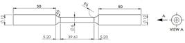
The brass C38500, a 2-phased leaded Cu- Zn alloy, with the commercial names of “free machining brass” and or “architectural bronze” was selected for the current research. This alloy is a one of the most common brass rods that has high machinability and some good mechanical properties such as moderate strength, wear, and corrosion resistance. A set of experiments were conducted to verify the prepared brass alloy based on ASTM-B455 ( ASTM 2010 ASTM (2010). Standard Specification for Copper-Zinc-Lead Alloy (Leaded-Brass) Extruded Shapes. B455, American Society for Testing & Materials. ). A tensile test was also performed based on ASTM-E8. Figure 1 shows the standard specimen for tensile test. The result of tensile test is also illustrated in Figure 2 and Table 1 . Rockwell-B macro hardness (HRB) test was also applied to determine the surface hardness and its result is shown in Table 1 . The chemical composition was obtained by quantometry test which is expressed in Table 2 .


In order to study the fatigue behavior, the rotary bending fatigue specimens were prepared based on uniform-gage test section of ASTM-E606 ( ASTM 1998 ASTM (1998). Standard Practice for Strain-Controlled Fatigue Testing1. E 606, American Society for Testing & Materials. ) ( Figure 3 ). To achieve accurate results, all of the specimens were fabricated using control numeric computer (CNC) lathe machine.
2.2 DCR tools and fatigue tests
To perform DCR treatment, a tool that is currently under patent pending was designed and fabricated, as shown in Figure 4 . This tool includes two ball-and-socket joints which can rotate freely over the specimen.

DCR tools; 1) fixture for mounting the tools in the lathe machine, 2) collet to hold the ball, 3) bearing, 4) hardened steel ball, 5) fixture for connecting the second tool, and 6) screw.
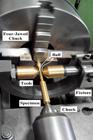
As shown in Figure 5 , DCR process was performed on the specimen using a lathe machine. The rotating ball penetrates to the specimen surface and starts to move along the specimen. In order to avoid lateral deflection of the sample, second DCR tool was added opposite of the first one, as illustrated in Figures 4 and 5 , Most of the DCR parameters were initially taken from Majzoobi et al. study ( Majzoobi et al. 2015 Majzoobi, G., et al. (2015). “Experimental and numerical studies on the effect of deep rolling on bending fretting fatigue resistance of Al7075.” The International Journal of Advanced Manufacturing Technology: 1-12. ).
DCR was performed with 90 rev/min rotational speed and 0.08 mm/rev longitudinal motion using DCR tools equipped with 6.35 mm diameter 57.6 HRC steel balls. The treatment was done under various rolling depths of 50, 75, 100, 125 and 150 µm in order to study the effects of this parameter on fatigue life and to find its optimum value. Moreover, the influence of repeating the treatment was studied on the final characteristics of the specimen. As mentioned before, the unilateral rotary bending fatigue test was carried out by an automatic device, Barsanj Electric- BSF500. The fatigue test was carried out under frequency of 50 Hz for rotational speed and 360 and 288 MPa bending stresses. These stress levels were chosen in a way to have both low and high cycle regimes. Some fatigue tests were also repeated to check the repeatability.
2.3 Fractography
The fractured sections of the specimens due to fatigue loading can represent fracture behavior. In the current study, Olympus-SZX10 stereo microscopy was used to examine the microstructural characteristics of the failed sections.
2.4. Surface Roughness
The major parameter to describe the surface quality especially in the field of fracture mechanics is the surface roughness ( Sayuti et al. 2013 Sayuti, M., et al. (2013). “Cutting force reduction and surface quality improvement in machining of aerospace duralumin AL-2017-T4 using carbon onion nanolubrication system.” The International Journal of Advanced Manufacturing Technology 65(9-12): 1493-1500. ). In general, roughness is not a desired parameter because of its unwanted effects on the fracture and initiation of surface cracks; however, it has a good effect on the stickiness. Roughness is determined by measuring the normal changes of surface. In the current study, the average roughness Ra was measured before and after the DCR process using Mahr-MarSurf M300-C roughness tester device.
2.5. Hardness
Generally, cold working increases the surface hardness. HRB macro-hardness tests were done before and after the DCR process using a Koopa-UV1 hardness tester instrument. As well, for determining the case depth hardness (subsurface hardness) in the material, Koopa-MH4 micro hardness tester was used to measure Vickers micro-hardness.
The mechanisms of hardening are different. DCR may induce high dislocation density, twining, martensitic and smaller microstructure. For investigating the reasons of work hardening, the microstructure has to be examined. Except dislocations, other signs of work hardening can be observed by metallography process. Regarding to two phases of the brass alloy (Alpha and Beta), a new etching method was applied for showing the microstructure perfectly. For this aim, first a strong etchant was used to clarify the grain boundaries and then, the darkened Beta phase etchant was used to show the phases. These etchants are expressed in Table 3 ( Paciornik et al. 2004 Paciornik, S., et al. (2004). “ASM Handbook: Metallography and Microstructures.” ASM Handbook: Metallography and Microstructures. ). Grains measurement was conducted by the image analysis software, MIP. This software works on the basis of ASTM E-112-96 standard ( ASTM 1996 ASTM (1996). “112, Standard test methods for determining average grain size.” ASTM International, PA, United States. ).
3. Finite Element Analysis
DCR process induces compressive residual stress in the surface and subsurface layers of the material and therefore, it is expected to retard the fatigue crack propagation. In this paper, distribution of residual stresses is studied using FE analysis. For more realistic simulation of DCR process, a 3D simulation is required which is very time consuming and has its complexity. However, a low computational cost 2D simulation with plane strain assumption can be used to estimate the stress distribution through DCR process ( Yen et al. 2005 Yen, Y., et al. (2005). “Finite element modeling of roller burnishing process.” CIRP Annals-Manufacturing Technology 54(1): 237-240. , Sartkulvanich et al. 2007 Sartkulvanich, P., et al. (2007). “Finite element modeling of hard roller burnishing: an analysis on the effects of process parameters upon surface finish and residual stresses.” Journal of Manufacturing Science and Engineering 129(4): 705-716. , Maximov and Duncheva 2011 Maximov, J. and G. Duncheva (2011). “Finite element analysis and optimization of spherical motion burnishing of low-alloy steel.” Proceedings of the Institution of Mechanical Engineers, Part C: Journal of Mechanical Engineering Science: 226: 247-264. , Sayahi et al. 2013 Sayahi, M., et al. (2013). “Finite element analysis of ball burnishing process: comparisons between numerical results and experiments.” The International Journal of Advanced Manufacturing Technology 67(5-8): 1665-1673. ). Under DCR, the ball pushes the sample surface slightly in the radial direction (about 100 micrometer) and there is no direct displacement in the circumferential (tangential) direction. In addition, due to complete lubrication of the interfaces the surface frictional forces between the ball and the sample surface are very small. Therefore, if a small section is taken into account, like what taken in the current research, a 2D model with the plane strain condition can be assumed ( Yen et al. 2005 Yen, Y., et al. (2005). “Finite element modeling of roller burnishing process.” CIRP Annals-Manufacturing Technology 54(1): 237-240. , Sartkulvanich et al. 2007 Sartkulvanich, P., et al. (2007). “Finite element modeling of hard roller burnishing: an analysis on the effects of process parameters upon surface finish and residual stresses.” Journal of Manufacturing Science and Engineering 129(4): 705-716. , Maximov and Duncheva 2011 Maximov, J. and G. Duncheva (2011). “Finite element analysis and optimization of spherical motion burnishing of low-alloy steel.” Proceedings of the Institution of Mechanical Engineers, Part C: Journal of Mechanical Engineering Science: 226: 247-264. , Sayahi et al. 2013 Sayahi, M., et al. (2013). “Finite element analysis of ball burnishing process: comparisons between numerical results and experiments.” The International Journal of Advanced Manufacturing Technology 67(5-8): 1665-1673. ). Whit this regard, a 5*3 mm rectangular part from longitudinal section of the fatigue specimen was chosen, as can be seen in Figure 6 , Material behavior was considered to be elasto-plastic with isotropic hardening behavior and was introduced to the software based on stress-strain curve obtained by tensile test (see Figure 2 and Table 1 ). The deep rolling ball was also considered analytical rigid due to its much more strength and stiffness than the brass C38500 specimen.

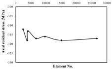
In order to get accurate response from FE analysis, a mesh refinement study has to be done. With this regard, different element numbers for the selected section were examined. Figure 7 shows the variation of axial residual stress caused by DCR under 75 µm rolling depth for a point with 0.9 mm depth against the number of elements. It is clear that the total element number of about 6800 leads to reasonable response and also avoids high computational cost. Therefore, the FE model was discretized using near 6800 CPE4R elements (4-node bilinear plane strain quadrilateral, reduced integration) for the main simulations.
Since the near surface area is more influenced by the rolling process, its stress distribution must be studied more precisely than other regions. Therefore, smaller element size was used for meshing the near surface area (see Figure 8 ). Boundary conditions (BCs) for the two dimensional FE model depicted in Figure 8 were adopted in a way to describe the real statement of the specimen. Applied BCs are illustrated in Figure 9 .

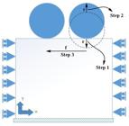
The boundary conditions and analysis steps; r: rolling depth, f: feed rate, step 1: loading, step 2: unloading, step 3: longitudinal movement.
As mentioned earlier, due to complete lubrication and also smooth rotation of the deep rolling ball over the specimen, the friction between the ball and the specimen is very small. With this regard, researchers have considered small values of friction coefficient in their FE simulations from frictionless state ( Majzoobi et al. 2015 Majzoobi, G., et al. (2015). “Experimental and numerical studies on the effect of deep rolling on bending fretting fatigue resistance of Al7075.” The International Journal of Advanced Manufacturing Technology: 1-12. ) to 0.1 ( Maximov and Duncheva 2011 Maximov, J. and G. Duncheva (2011). “Finite element analysis and optimization of spherical motion burnishing of low-alloy steel.” Proceedings of the Institution of Mechanical Engineers, Part C: Journal of Mechanical Engineering Science: 226: 247-264. ). In current research, the more realistic friction coefficient of 0.1 was taken into account. Solution step was selected as static-general and the problem was solved implicitly. Load steps were also defined how to simulate relative movement of the ball and the specimen. For this purpose, the ball moves 75 micrometer in direction –Y to penetrate the specimen and then moves back to position 0 and moves horizontally over the specimen in direction X equal to 0.08 mm to model the feed movement. The horizontal displacement is the pitch value that can be calculated simply having the rotational speed and the feed rate of the DCR tool. This displacement step was repeated 44 times to simulate the DCR treatment completely. Figure 9 expresses schematic representation of these steps. In order to validate the FE model accuracy, the results were initially compared with 2D simulation of Sayahi et al. (2013) Sayahi, M., et al. (2013). “Finite element analysis of ball burnishing process: comparisons between numerical results and experiments.” The International Journal of Advanced Manufacturing Technology 67(5-8): 1665-1673. . They simulated the effects of ball burnishing on the Ti-6Al-7Nb alloy.
In their study, the material behavior was defined based on Table 4 and the plastic behavior was assumed to obey the following equation:
where εP is the plastic strain. They used CPE8 (eight-node biquadratic 2D solid plane strain) element and the burnishing depth and the feed rate were considered 12 micrometers and 0.2 mm/rev, respectively. To validate our FE model, Sayahi’s model was simulated in ABAQUS commercial software and the obtained residual stresses were compared with Sayahi’s results. As Figure 10 suggests, an acceptable agreement between current model and Sayahi’s model can be observed.
Properties of Ti-6Al-7Nb in Sayahi’s work ( Sayahi et al. 2013 Sayahi, M., et al. (2013). “Finite element analysis of ball burnishing process: comparisons between numerical results and experiments.” The International Journal of Advanced Manufacturing Technology 67(5-8): 1665-1673. ).

4. Results and discussion
4.1 Fatigue life
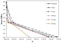
Figure 11 illustrates the fatigue life of cyclically loaded specimens under different rolling depths. This figure indicates that the rolling depth of 75 µm can lead to the best life improvement. As the figure suggests, when the specimen is subjected to 360 MPa bending stress (the low cycle fatigue (LCF) regime), all of the rolling depths increase the fatigue life, but the best result is obtained by 75 µm rolling depth. It is notable to add that rolling depths smaller than 100 µm could more increase the fatigue life compared to deeper penetration such as 125 and 150 µm. This is may be due to crack initiation caused by applying high pressures during deeper penetrations. DCR by 75 µm could increase the fatigue life of the material under 360 MPa cyclic loading from about 11000 to 46000 rounds which is near 300% improvement. This improvement was measured about 20% (from 282000 to 338000 round) when the specimen was subjected to 288MPa cyclic loading (the high cycle fatigue (HCF) regime).
The effects of number of DCR passes on the fatigue life were also investigated. With this regards, two rolling depths of 75 and 100 µm were selected and DCR process was performed for the second time. As illustrated in Figures 12 and 13 , repeating the DCR treatment under 75 and 100 µm could increase the fatigue life by about 44% (282000 to 408000 rounds) and about 41% (282000 to 398000 round), respectively. It can be realized from Figures 11 - 13 that DCR is more effective in LCF than HCF loading regimes for brass C38500.

Fatigue diagram of deep rolled brass C38500 for 1 and 2 passes of DCR under 75 µm rolling depth.
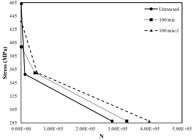
Fatigue diagram of deep rolled brass C38500 for 1 and 2 passes of DCR under 100 µm rolling depth.
4.2 Fractography
Figure 14 illustrates the fractured sections of untreated specimens subjected to two different cyclic loading levels, i.e. 360 and 288 MPa. The fatigue fractured surface consists of two sections including the fatigue area which is smooth and shine and the fast fracture area or tension area which is rough and dark. It should be noted that the cracks initiate and then propagate in the fatigue area. When the cracks reach to the critical length, the material becomes very feeble that cannot tolerate more crack propagation and therefore, brittle fracture may occur ( Totten 2008 Totten, G. (2008). “Fatigue crack propagation.” Advanced Materials and Processes 166(5): 39. ). As can be seen in Figure 14 (a), some ratchet which the cracks initiated between them are clear ( Totten 2008 Totten, G. (2008). “Fatigue crack propagation.” Advanced Materials and Processes 166(5): 39. , Mashhadi et al. 2017 Mashhadi, A., et al. (2017). “Mechanical and microstructural investigation of Zn/Sn multilayered composites fabricated by accumulative roll bonding (ARB) process.” Journal of Alloys and Compounds 727: 1314-1323. ). The ratchets and origins are denoted by (R) and (O) in Figure 14 (a), respectively.
Unilateral bending fatigue fractured sections of untreated materials subjected to (a) 360 MPa, and (b) 288 MPa.
In Figure 14 (b), the limited beach marks can be observed that are usually created in some materials under HCF regimes. Comparing Figure 14 (a) with Figure 14 (b) gives that the fatigue area (the area including the crack growth) is bigger for lower loads. In order to investigate the effects of DCR on fractured section of the specimens, a typical fractured section under 75 µm rolling depth is shown in Figurer 15 .

Compared to Figure 14 (b), the fast fracture area in Figure 15 is shrunk after DCR which means the fatigue life has been improved.
4.3 Surface roughness
DCR as a surface treatment can reduce surface roughness significantly. This process can lead to surface crack retardation and also to fatigue life improvement. As Table 5 expresses, the surface roughness of brass C38500 alloy is decreased from 1.523 µm to about 0.19 µm after two passes of DCR under 75 m rolling depth. This result agrees with mathematical model of Hassan et al. (1998) Hassan, A., et al. (1998). “Burnishing force and number of ball passes for the optimum surface finish of brass components.” Journal of Materials Processing Technology 83(1): 176-179. for ball burnishing of brass samples based on Equation (2) .
where and . Other researchers ( Hassan and Al-Bsharat 1996 Hassan, A. M. and A. S. Al-Bsharat (1996). “Improvements in some properties of non-ferrous metals by the application of the ball-burnishing process.” Journal of Materials Processing Technology 59(3): 250-256. , Hassan 1997 Hassan, A. M. (1997). “The effects of ball-and roller-burnishing on the surface roughness and hardness of some non-ferrous metals.” Journal of Materials Processing Technology 72(3): 385-391. , Hassan et al. 1998 Hassan, A., et al. (1998). “Burnishing force and number of ball passes for the optimum surface finish of brass components.” Journal of Materials Processing Technology 83(1): 176-179. , Hassan and Al-Dhifi 1999 Hassan, A. M. and Al-Dhifi, S. Z. (1999). “Improvement in the wear resistance of brass components by the ball burnishing process.” Journal of Materials Processing Technology 96(1): 73-80. , Abrão et al. 2014a Abrão, A., et al. (2014a). “Surface and subsurface alterations induced by deep rolling of hardened AISI 1060 steel.” Production Engineering 8(5): 551-558. , 2014b Abrão, A., et al. (2014b). “The influence of deep rolling on the surface integrity of AISI 1060 high carbon steel.” Procedia CIRP 13: 31-36. , Sarhan and El-Tayeb 2014 Sarhan, A. A. and N. El-Tayeb (2014). “Investigating the surface quality of the burnished brass C3605—fuzzy rule-based approach.” The International Journal of Advanced Manufacturing Technology 71(5-8): 1143-1150. ) also obtained similar effects of DCR or roller/ball burnishing on roughness and surface quality of metallic alloys and could successfully increase the fatigue life. Smooth surfaces with least roughness have generally a few number of stress concentration points which may cause to retard surface crack initiation and propagation and in turn to improve the fatigue life mainly in LCF regimes, as illustrated in Figures 11 - 13 .
4.4 Hardness
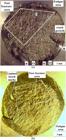
The mechanisms of plastic deformation caused by strain hardening are usually sliding and twining which first one is more common. Twining induces in the bcc and hcp metals when are subjected to low temperature and high rate loadings. But, for fcc metals twining occurs only when the stacking fault energy (SFE) is negligible ( Dieter and Bacon 1986 Dieter, G. E. and D. J. Bacon (1986). Mechanical metallurgy, McGraw-Hill New York. ). Copper is an fcc metal which adding Zinc element decreases its SFE significantly. Brass alloy used in the current study has 39% Zinc and therefore, has low SFE and has high tendency to twining. Current brass alloy (C38500) was hardened by rolling during mass production and therefore, contains some twins in its structure. DCR has also similar effect on this alloy as well and increases the numbers of these twin boundaries. For better investigation of the effects of DCR on the grain size, small area shown in Figure 16 is considered. Grain measurement obtained by image analysis is expressed in Table 6 . The results show grain refinement after DCR process. Smaller grain size is a reason for increasing the hardness of brass C38500. In Figure 17 , the microstructure of wrought material treated by 75 rolling depth and its repetition is shown. Twin boundaries can be observed in these figures which are the signs of rolling and DCR process.


Microstructure of (a) untreated, (b) treated by DCR under 75 µm rolling depth, and (c) 2 pass DCR under 75 µm rolling depth.
The HRB macro-hardness variations on the surface and cross section of the specimens are shown in Table 7 and Figure 18 , respectively. Harmonic variations of macro-hardness in Figure 18 is similar to what obtained by Abrão et al. (2014a) Abrão, A., et al. (2014a). “Surface and subsurface alterations induced by deep rolling of hardened AISI 1060 steel.” Production Engineering 8(5): 551-558. .

Subsurface Vickers micro-hardness variation in the cross section of treated and untreated C38500 brass alloy.
As Table 7 suggests, DCR treatment has increased the surface hardness (HRB macro-hardness) although its repetition restored it slightly. Plastic deformation ability of metals depends on the ability of dislocations movement. Work hardening in metals are also caused by dislocation movements ( Dieter and Bacon 1986 Dieter, G. E. and D. J. Bacon (1986). Mechanical metallurgy, McGraw-Hill New York. ). When the dislocation density reaches to a saturated amount, they cannot move and the further plasticity deformation cannot occur. Therefore, more hardness improvement would be impossible. In other hand, since the brass C38500 is a 2-phased material, its phase β causes low ability to accept the cold working ( Smith and Hashemi 2011 Smith, W. F. and J. Hashemi (2011). Foundations of materials science and engineering, McGraw-Hill. ). Therefore, repeating the process has not any improvement for surface hardness and even may decrease it.
Case depths hardness (Vickers micro-hardness) is increased by deep rolling too, but repeating the treatment may decrease the hardness slightly. Similar result is also reported for hardened AISI 1060 steel ( Abrão et al. 2014a Abrão, A., et al. (2014a). “Surface and subsurface alterations induced by deep rolling of hardened AISI 1060 steel.” Production Engineering 8(5): 551-558. ). Main reasons of having a limit for hardness elevation after increasing the number of DCR pass is better distribution of dislocations during repeating the treatment and also low hardness capacity of brass C38500. Repeating the treatment induces more increment in subsurface layers than deeper layers. Therefore, refined microstructure and twinning phenomenon are known to be the main reasons of work hardening in this research. At the end, the variational behavior of micro-hardness can be attributed to the residual stresses inside the material that affects the indentation force F (see Equation 3 ) as well as the two-phase structure of C38500 alloy which both of these phase are smaller than the Vickers indenter ( Dieter and Bacon 1986 Dieter, G. E. and D. J. Bacon (1986). Mechanical metallurgy, McGraw-Hill New York. ).
4.5 Residual stress
The average of residual stresses in several paths (similar to AB in Figure 8 ) in the plastic deformation area (the region between points C and D in Figure 8 ) for rolling depth of 75 µm was calculated using FE simulations and are shown in Figure 19 .

Average distribution of residual stresses between points C and D depicted in Figure 8 due to DCR under 75 µm rolling depth.
Generally, the compressive residual stress leads to crack closure and in turn, to crack retardation. The range of stress intensity factor which is caused by the crack is explained by Equation 4 ( Dieter and Bacon 1986 Dieter, G. E. and D. J. Bacon (1986). Mechanical metallurgy, McGraw-Hill New York. ).
Where σr is the difference between the tensile and compressive stresses. The compressive residual stress gives rise to reduction of this amount and therefore, helps to delay fatigue fracture. As Figure 19 illustrates, the quantity of compressive residual stresses increases until reaching to the maximum amount and then reduces. It is clear that the effect of residual stress is more influencing in subsurface layers and decreases in deeper regions of the specimen.
5. Conclusion
Based on the investigations in current paper, following remarks may be drawn:
-
1
DCR by 50, 75 and 100 µm rolling depths could increase the HCF life, whereas DCR by higher rolling depths led to reduction of HCF tolerance. DCR by all rolling depths from 50 to 150 µm could improve the LCF life of brass C38500.
-
2
Rolling depth of 75 µm had the best effect on the fatigue life improvement where could enhance the high and low cycle fatigue lives by about 20 and 300 percent, respectively.
-
3
Repeating the treatment improved the fatigue life significantly so that near 350% and 46% improvement was observed in the LCF and HCF regimes, respectively.
-
4
DCR under rolling depth of 75 µm reduced the roughness by about 85%. Repeating the treatment for the second time also reduced this parameter by about 88%.
-
5
The microstructure study showed that the hardening mechanisms of brass C38500 may be grain refinement and twin boundaries.
-
6
Brass C38500 is a weak alloy for cold work, but DCR could increase its hardness slightly (about 5%).
-
7
FE simulations showed good effects of DCR in inducement of compressive residual stresses and in turn, in improvement of the alloy fatigue life.
References
- Abrão, A., et al. (2014a). “Surface and subsurface alterations induced by deep rolling of hardened AISI 1060 steel.” Production Engineering 8(5): 551-558.
- Abrão, A., et al. (2014b). “The influence of deep rolling on the surface integrity of AISI 1060 high carbon steel.” Procedia CIRP 13: 31-36.
- Abrão, A., et al. (2015). “The inducement of residual stress through deep rolling of AISI 1060 steel and its subsequent relaxation under cyclic loading.” The International Journal of Advanced Manufacturing Technology 79(9-12): 1939-1947.
- Altenberger, I. (2005). Deep rolling—the past, the present and the future. Proceedings of 9th International Conference on Shot Peening, Sept.
- Altenberger, I. and Scholtes, B. (2000). Recent developments in mechanical surface optimization. Materials science forum, Trans Tech Publ.
- Altenberger, I., et al. (1999). “Cyclic deformation and near surface microstructures of shot peened or deep rolled austenitic stainless steel AISI 304.” Materials Science and Engineering: A 264(1): 1-16.
- Altenberger, I., et al. (2008). Effect of deep rolling on the cyclic performance of magnesium and aluminum alloys in the temperature range 20–250 C. Proceedings of the 10th International Conference on Shot Peening (ICSP), ACMU, Tokyo, Japan.
- ASTM (1996). “112, Standard test methods for determining average grain size.” ASTM International, PA, United States.
- ASTM (1998). Standard Practice for Strain-Controlled Fatigue Testing1. E 606, American Society for Testing & Materials.
- ASTM (2010). Standard Specification for Copper-Zinc-Lead Alloy (Leaded-Brass) Extruded Shapes. B455, American Society for Testing & Materials.
- Atrian, A. and Mombeini, D. (2016). Investigation the effect of deep cold rolling on the surface quality of brass C38500. XMech 2016. Iran, Tehran.
- Balland, P., et al. (2013). “An investigation of the mechanics of roller burnishing through finite element simulation and experiments.” International Journal of Machine tools and manufacture 65: 29-36.
- Beghini, M., et al. (2014). “Experimental parameter sensitivity analysis of residual stresses induced by deep rolling on 7075-T6 aluminium alloy.” Surface and Coatings Technology 254: 175-186.
- Bozdana, A. T., et al. (2005). “Deep cold rolling with ultrasonic vibrations—a new mechanical surface enhancement technique.” International Journal of Machine tools and manufacture 45(6): 713-718.
- Dieter, G. E. and D. J. Bacon (1986). Mechanical metallurgy, McGraw-Hill New York.
- Hassan, A. M. (1997). “The effects of ball-and roller-burnishing on the surface roughness and hardness of some non-ferrous metals.” Journal of Materials Processing Technology 72(3): 385-391.
- Hassan, A. M. and A. S. Al-Bsharat (1996). “Improvements in some properties of non-ferrous metals by the application of the ball-burnishing process.” Journal of Materials Processing Technology 59(3): 250-256.
- Hassan, A. M. and Al-Dhifi, S. Z. (1999). “Improvement in the wear resistance of brass components by the ball burnishing process.” Journal of Materials Processing Technology 96(1): 73-80.
- Hassan, A., et al. (1998). “Burnishing force and number of ball passes for the optimum surface finish of brass components.” Journal of Materials Processing Technology 83(1): 176-179.
- Hassani-Gangaraj, S., et al. (2015). “Finite element approach toward an advanced understanding of deep rolling induced residual stresses, and an application to railway axles.” Materials & Design 83: 689-703.
- Juijerm, P. and I. Altenberger (2007a). “Effect of high-temperature deep rolling on cyclic deformation behavior of solution-heat-treated Al–Mg–Si–Cu alloy.” Scripta materialia 56(4): 285-288.
- Juijerm, P. and I. Altenberger (2007b). “Effective boundary of deep-rolling treatment and its correlation with residual stress stability of Al–Mg–Mn and Al–Mg–Si–Cu alloys.” Scripta materialia 56(9): 745-748.
- Klesnil, M. and P. Lukáš (1992). Fatigue of metallic materials, Elsevier.
- Klocke, F., et al. (2011). “Finite element analysis of the roller burnishing process for fatigue resistance increase of engine components.” Proceedings of the Institution of Mechanical Engineers, Part B: Journal of Engineering Manufacture 225(1): 2-11.
- Lindemann, J., et al. (2003). “Influence of Shot Peening and Deep Rolling on High Temperature Fatigue of the Ni‐Superalloy Udimet 720 LI.” Shot Peening: 454-460.
- Magalhaes, F. C., et al. (2016). “Analytical Modeling of Surface Roughness, Hardness and Residual Stress Induced by Deep Rolling.” Journal of materials engineering and performance: 1-9.
- Majzoobi, G., et al. (2015). “Experimental and numerical studies on the effect of deep rolling on bending fretting fatigue resistance of Al7075.” The International Journal of Advanced Manufacturing Technology: 1-12.
- Mashhadi, A., et al. (2017). “Mechanical and microstructural investigation of Zn/Sn multilayered composites fabricated by accumulative roll bonding (ARB) process.” Journal of Alloys and Compounds 727: 1314-1323.
- Maximov, J. and G. Duncheva (2011). “Finite element analysis and optimization of spherical motion burnishing of low-alloy steel.” Proceedings of the Institution of Mechanical Engineers, Part C: Journal of Mechanical Engineering Science: 226: 247-264.
- Nikitin, I. A., Scholtes (2005). Cyclic deformation behaviour of deep rolled and laser-shock peened AISI 304 stainless steel at elevated temperature. International Conference on Fracture (ICF11) Torino, Italy. 8: 6213-6218.
- Nikitin, I., et al. (2005a). “Effect of deep rolling at elevated and low temperatures on the isothermal fatigue behavior of AISI 304.”
- Nikitin, I., et al. (2005b). Residual stress state and cyclic deformation behaviour of deep rolled and laser-shock peened AISI 304 stainless steel at elevated temperatures. Materials Science Forum, Trans Tech Publ.
- Nusskern, P., et al. (2014). “Powder Metallurgical Components: Improvement of Surface Integrity by Deep Rolling and Case Hardening.” Procedia CIRP 13: 192-197.
- Paciornik, S., et al. (2004). “ASM Handbook: Metallography and Microstructures.” ASM Handbook: Metallography and Microstructures.
- Padilla II, H. and B. Boyce (2010). “A review of fatigue behavior in nanocrystalline metals.” Experimental mechanics 50(1): 5-23.
- Prabhu, P., et al. (2012). “Deep Cold Rolling Process on AISI 4140 Steel and Optimization of Surface Roughness by Response Surface Methodology.” International Conference on Mechanical Production and Materials Engineering (ICMPME'2012), Thailand, Bangkok. 25-29.
- Sarhan, A. A. and N. El-Tayeb (2014). “Investigating the surface quality of the burnished brass C3605—fuzzy rule-based approach.” The International Journal of Advanced Manufacturing Technology 71(5-8): 1143-1150.
- Sartkulvanich, P., et al. (2007). “Finite element modeling of hard roller burnishing: an analysis on the effects of process parameters upon surface finish and residual stresses.” Journal of Manufacturing Science and Engineering 129(4): 705-716.
- Sattari, S., et al. (2017). “The effects of deep rolling process on surface roughness and properties of Al-3 vol% SiCnp nanocomposite fabricated by mechanical milling and hot extrusion.” International Journal of Minerals, Metallurgy, and Materials.
- Sayahi, M., et al. (2013). “Finite element analysis of ball burnishing process: comparisons between numerical results and experiments.” The International Journal of Advanced Manufacturing Technology 67(5-8): 1665-1673.
- Sayuti, M., et al. (2013). “Cutting force reduction and surface quality improvement in machining of aerospace duralumin AL-2017-T4 using carbon onion nanolubrication system.” The International Journal of Advanced Manufacturing Technology 65(9-12): 1493-1500.
- Shigley, J. E. (2011). Shigley's mechanical engineering design, Tata McGraw-Hill Education.
- Smith, W. F. and J. Hashemi (2011). Foundations of materials science and engineering, McGraw-Hill.
- Totten, G. (2008). “Fatigue crack propagation.” Advanced Materials and Processes 166(5): 39.
- Yang, H., et al. (2012). “The Influence of Stacking Fault Energy on Compression Test of Cu and Cu-Al Alloys.” Procedia Engineering 36: 307-315.
- Yen, Y., et al. (2005). “Finite element modeling of roller burnishing process.” CIRP Annals-Manufacturing Technology 54(1): 237-240.
- Zare Jouneghani, F., et al. (2015). “Studying the distribution of residual stresses in deep rolling process of Al 7075.” Modares Mechanical Engineering 15(7): 9.
Publication Dates
-
Publication in this collection
04 June 2018 -
Date of issue
2018
History
-
Received
26 July 2017 -
Reviewed
05 Oct 2017 -
Accepted
22 Oct 2018


