Abstract
A one-dimensional finite element model for buckling analysis of hybrid piezoelectric beams under electromechanical load is presented in this work. The coupled zigzag theory is used for making the model. The inplane displacement is approximated as a combination of a global third order variation across the thickness with an additional layer wise linear variation. The longitudinal electric field is also taken into account. The deflection field is approximated to account for the transverse normal strain induced by electric fields. Two nodded elements with four mechanical and a variable number of electric degrees of freedom at each node are considered. To meet the convergence requirements for weak integral formulation, cubic Hermite interpolation function is used for deflection and electric potential at the sub-layers and linear interpolation function is used for axial displacement and shear rotation. The expressions for the variationally consistent stiffness matrix and load vector are derived and evaluated in closed form using exact integration. The present 1D-FE formulation of zigzag theory is validated by comparing the results with the analytical solution for simply-supported beam and 2D-FE results obtained using ABAQUS. The finite element model is free of shear locking. The critical buckling parameters are obtained for clamped-free and clamped-clamped hybrid beams. The obtained results are compared with the 2D-FE results to establish the accuracy of the zigzag theory for above boundary conditions. The effect of lamination angle on critical buckling load is also studied.
Piezoelectric beam; FEM; Buckling; Zigzag theory; ABAQUS
Finite element modeling for buckling analysis of hybrid piezoelectric beam under electromechanical loads
Najeeb ur RahmanI,* * Author email: najeebalig@rediffmail.com ; M.Naushad AlamII
IDepartment of Mechanical Engineering, Aligarh Muslim University, Aligarh,U.P-202002, India
IIDepartment of Mechanical Engineering, Aligarh Muslim University, Aligarh,U.P-202002, India
ABSTRACT
A one-dimensional finite element model for buckling analysis of hybrid piezoelectric beams under electromechanical load is presented in this work. The coupled zigzag theory is used for making the model. The inplane displacement is approximated as a combination of a global third order variation across the thickness with an additional layer wise linear variation. The longitudinal electric field is also taken into account. The deflection field is approximated to account for the transverse normal strain induced by electric fields. Two nodded elements with four mechanical and a variable number of electric degrees of freedom at each node are considered. To meet the convergence requirements for weak integral formulation, cubic Hermite interpolation function is used for deflection and electric potential at the sub-layers and linear interpolation function is used for axial displacement and shear rotation. The expressions for the variationally consistent stiffness matrix and load vector are derived and evaluated in closed form using exact integration. The present 1D-FE formulation of zigzag theory is validated by comparing the results with the analytical solution for simply-supported beam and 2D-FE results obtained using ABAQUS. The finite element model is free of shear locking. The critical buckling parameters are obtained for clamped-free and clamped-clamped hybrid beams. The obtained results are compared with the 2D-FE results to establish the accuracy of the zigzag theory for above boundary conditions. The effect of lamination angle on critical buckling load is also studied.
Keywords: Piezoelectric beam, FEM, Buckling, Zigzag theory, ABAQUS.
1 INTRODUCTION
Structural components made with hybrid composite laminates and sandwich structures with surface bonded or embedded piezoelectric layers are increasingly being used in various engineering applications in aerospace, naval, civil, and mechanical industries. This is due to their attractive properties in strength, stiffness, and lightness. In such applications buckling phenomenon is often observed which is critically dangerous to structural components as it usually occurs at a lower applied stress for such structures, and it generates large deformation. Understanding their dynamic and buckling behaviour is of increasing importance.
There have been few exact three-dimensional (3D) solutions of buckling of elastic composite and sandwich plates and exact 2D solutions of buckling of composite and sandwich beams. These solutions serve as useful benchmarks for assessment of various 1D beam theories and approximate 2D numerical solutions such as the solution using the finite element method. Song and Waas (1987) presented a higher order theory for the buckling and vibration analysis of composite beams and the accuracy of HSDT was demonstrated compared to 1-D Euler-Bernoulli, 2-D classical elasticity theory and Timoshenko beam theory. Chandrashekhra and Bhatia (1993) presented a finite element model for active buckling control of composite plates, with surface bonded or embedded, continuous or segmented, piezoelectric sensors and actuators. Khdeir and Reddy (1997) developed analytical solutions for free vibration and buckling of cross-ply composite beams with arbitrary boundary conditions in conjunction with the state space approach. Wang (2002) and Wang and Quek (2002) have presented coupled 1D classical beam theory for buckling and further analysis of a column with a pair of piezoelectric layers partially or fully covering it. Finite difference method is used for solution and it is shown that with proper placement of the actuators, the buckling load for the statically actuated beams can be significantly increased. Thompson and Loughlan (1995) demonstrated experimentally that the buckling capacity of a column is increased by applying controlled voltage to the piezoelectric actuators. Kapuria and Alam (2004) presented a twodimensional exact piezoelasticity solution for buckling of simply supported symmetrically laminated hybrid beam and cross-ply panel with elastic substrate and piezoelectric layers. They considered buckling under axial strain and actuation potentials for movable inplane end conditions and under actuation potential alone for immovable inplane end conditions. Kapuria and Alam (2004) developed a new efficient coupled one-dimensional (1D) geometrically nonlinear zigzag theory for buckling analysis of hybrid piezoelectric beams, under electromechanical loads. They approximated potential field layerwise as piecewise linear. Kamruzzaman et al. (2006) performed parametric studies to identify better configuration of given composite to achieve higher buckling strength for laminated anti-symmetric cross and angle-ply simply supported rectangular orthotropic plates subjected to uniaxial compressive loads. Kapuria and Alam (2005) developed an efficient electromechanically coupled geometrically nonlinear zigzag theory for buckling analysis of hybrid piezoelectric beams, under electro-thermomechanical loads. They obtained analytical solutions for buckling of symmetrically laminated simply supported beams under electrothermal loads and compared the results with the available exact two-dimensional (2D) piezo-thermoelasticity solution. Anas et al. (2011) developed a one dimensional finite element model for the buckling analysis of laminated composite beam, using the efficient layer wise zigzag theory. They obtained the 1D-FE results for cantilever beam and compared with the 2D-FE results, obtained using ABAQUS. Anas and Husain (2012) have used an efficient one dimensional finite element model for the vibrational analysis of composite laminated symmetric beam, using the efficient layerwise zigzag theory.
Vo and Inam (2012) presented vibration and buckling analysis of cross-ply composite beams using refined shear deformation theory. The theory accounts for the parabolical variation of shear strains through the depth of beam. They obtained numerical results for composite beams to investigate modulus ratio on the natural frequencies, critical buckling loads and load-frequency interaction curves.
Qiao et al. (2010) derived local delamination buckling formulas for laminated composite beams based on the rigid, semi rigid, and flexible joint models with respect to three bilayer beam theories. They analyzed two local delamination buckling modes and obtained their critical buckling loads based on the three joint models. Chakrabarti et al. (2012) studied stability analysis of laminated soft core sandwich beam by a FE model developed by the authors based on higher order zigzag theory (HOZT).The proposed model satisfies the condition of stress continuity at the layer interfaces and the zero stress condition at the top and bottom of the beam for transverse shear. Alam and Anas (2009) have used an efficient one dimensional finite element model developed for the buckling analysis of composite laminated beams, using the efficient layer wise zigzag theory. They compared 1D-FE results for cantilever beam with the 2D-FE results, obtained using ABAQUS. Sherwani and Alam (2009) have used an efficient one dimensional finite element model for the buckling analysis of smart beam, using the efficient layer wise zigzag theory. The employed finite element model is free of shear locking and obtained results of buckling parameters for cantilever smart beam. Kapuria and Alam (2005) developed a new efficient electromechanically coupled geometrically nonlinear zigzag theory for buckling analysis of hybrid piezoelectric beams, under electrothermomechanical loads. The thermal and potential fields are approximated as piecewise linear in sublayers. Analytical solutions for buckling of symmetrically laminated simply supported beams under electro-thermal loads are obtained for comparing the results with the available exact two-dimensional piezo-thermoelasticity solution. Pandit et.al (2008) have proposed a higher order zigzag theory for the static and buckling analysis of sandwich plates with soft compressible core. They employed a nine node isoparametric element with 11 field variables per node. To overcome the problem of C1continuity the authors have used separate shape functions to define the derivatives of transverse displacements. Matsunaga (1996, 2001) developed a one dimensional global higher order theory, in which the fundamental equations were derived based on the power series expansions of continuous displacement components to analyze the vibration and buckling problems. Cetkovic and Vuksanovic (2009) and many others assume unique displacement field in each layer and displacement continuity across the layers. In these theories, the number of unknowns increases directly with the increase in the number of layers due to which it required huge computational involvement. Aydogdu (2006) carried out the vibration and buckling analysis of cross-ply and angle-ply with different sets of boundary conditions by using Ritz method. Iqbal et al. (2011) have studied free vibration response of laminated sandwich beams having a soft core by using a C0 finite element beam model. The model has been developed based on higher order zigzag theory where the in-plane displacement variation is considered to be cubic for both the face sheets and the core.
Moy et al. (2005) developed a shear deformable plate bending element based on a third order shear deformable theory (i.e. HSDT). Dawe and Yuan (2001) used a B-spline finite strip method (FSM) for predicting the buckling stresses of rectangular sandwich plates. They represented core as a three-dimensional solid in which the in-plane displacements vary quadratically through the thickness whilst the out-of-plane displacement varies linearly. Herbert et al. (2012) used a consistently linearized Eigen-problem to derive mathematical conditions in the frame of the Finite Element Method (FEM) for loss of static stability of elastic structures at prebuckling states. Cai etal. (2011) presented the buckling behaviours of composite long cylinders subjected to external hydrostatic pressure by using deterministic and probabilistic finite element analyses. They studied the effects of uncertainties of material properties and physical dimensions on the critical buckling pressure. Kheirikhah et al. (2012) presented an accurate 3D finite element model for bucking analysis of soft-core rectangular sandwich plates. They studied the effect of geometrical parameters of the sandwich plate.
A detailed review of literature shows that although considerable research work has been done on buckling of composite beams, but the finite element modelling for buckling analysis of hybrid beams for various boundary conditions using zigzag theory is missing. Keeping this point in view a one-dimensional finite element model is presented in this work for buckling analysis of hybrid piezoelectric beams under electromechanical load. The coupled zigzag theory by Kapuria and Alam (2004) is used for making the model. The inplane displacement is approximated as a combination of a global third order variation across the thickness with an additional layer wise linear variation. The longitudinal electric field is also taken into account. The deflection field is approximated to account for the transverse normal strain induced by electric fields. Two nodded elements with four mechanical and a variable number of electric degrees of freedom at each node are considered. The critical buckling parameters are obtained for clamped-free and clamped-clamped smart beams. The 1D-FE results are compared with 2-D FE results obtained using ABAQUS.
2 ONE DIMENSIONAL COUPLED ZIGZAG THEORY FOR HYBRID PIEZOELECTRIC BEAM
Consider a hybrid beam having any lay-up, whose thickness h and the number of layers L may vary segment-wise [Kapuria and Alam (2004)] due to the presence of piezoelectric patches. The longitudinal and thickness axes are along x - and z directions. The xy - plane is chosen to be the plane which is the midplane for most of the length of the beam. Let the planes z=z0 and z=zL be the bottom and top surfaces of the beam, which may vary segment-wise. The z - coordinate of the bottom surface of the kth layer (numbered from the bottom) is denoted as zk-1 and its material symmetry direction 1 is at an angle θk to the x axis. The reference plane z = 0 either passes through or is the bottom surface of the  layer. All the elastic and piezoelectric layers are perfectly bonded. It is loaded transversely on the bottom and top with no variation along the width b . The piezoelectric layers have poling direction along z - axis.
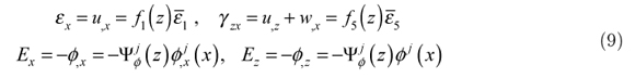
The approximations of the coupled zigzag theory presented by Kapuria and Alam (2004) are as follows. For a beam with a small width, a state of plane stress is assumed i.e. σy = τyz = τxy = 0. For infinite panels, a plane strain state (εy = γyz = γxy = 0) is considered. The transverse normal stress is neglected (i.e.σz = 0). The axial and transverse displacements u,w and electric potential ϕ are assumed to be independent of y . With these assumptions, the general 3D constitutive equations of a piezoelectric medium for stresses σx,τzx and electric displacements Dx, Dz reduce to
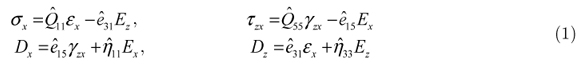
Where  are the reduced stiffness coefficients, piezoelectric stress constants and electric permittivities respectively.
The potential field ϕ is assumed as piecewise linear between nϕ points  across the thickness:

where
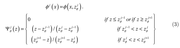
 (z) are linear interpolation functions and summation convention is used with the summation index j, taking values 1,2,...,nϕ. This description allows the piezoelectric layers to be divided into a number of sub-layers and a series of elastic layers to be combined into one, for effective modeling of ϕ across the thickness. The variation of deflection w is obtained by integrating the constitutive equation for εz by neglecting the contribution of σx via Poisson's effect compared to that due to the electric field: w,z ; d33ϕ,z⇒

where 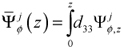 is a piecewise linear function. The axial displacement u for the kth layer is approximated to follow a global third order variation across the thickness with a layerwise linear variation:

For the layer through which the plane z = 0 passes, denote u0 (x) = uk0 (x) = u (x,0), ψk0 (x) = ψk0 (x). Thus u0 and ψ0 are the axial displacement and the shear rotation at z=0, respectively. Using the (L 1) conditions each for the continuity of τzx and u at the layer interfaces and the two shear traction-free conditions τzx = 0 at z = ±h / 2 , the functions uk,ψk,ξ,η are expressed in terms of u0 and ψ0 to yield

where Rk (z),Rk (z) are cubic functions of z whose coefficients are dependent on the material properties and lay-up.
Thus, even though w,u have layerwise distributions, they are expressed in terms of only three displacement variables u0, w0, ψ0 by Eqns. (4) and (6).
Eqns. (6) and (4) for u , w can expressed as

with
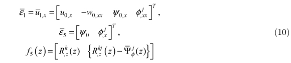
where elements with index j mean a sequence of elements with j = 1 to nϕ. Using Eqn. (7) and (2), the strains and the electric fields can be expressed as
where
Let  be the normal forces per unit area on the bottom and top surfaces of the beam in direction z . Let there be distributed viscous resistance force with the distributed viscous damping coefficient c1 per unit area per unit transverse velocity of the top surface of the beam. At the interface at z =
  where the potential is prescribed, the extraneous surface charge density is qij. Using the notation ... =
  for integration across the thickness, the extended Hamilton's principle for the beam reduces to
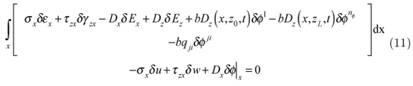
Substituting the expressions (7) and (2) for u,w,ϕ and (9) for εx, γzx, Ex, Ez into Eqn. (11) yields
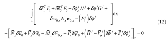
where an over-bar on the stress and electric resultants and on u0, w0, ψ0, ϕj means values at the ends.
3 FINITE ELEMENT MODEL OF HYBRID BEAM
A finite element model using the 1D coupled zigzag theory is developed for the buckling analysis of hybrid piezoelectric beams (Fig.1) under electromechanical loads. Two noded elements are used for the electromechanical variables.
The highest derivatives of u0, ψ0, w0, ϕj appearing in the variational Eqn. (12) are u0,x, ψ0,xx, w0,x,  . To meet the convergence requirements, the interpolation functions for u0, ψ0, w0,x,
  must be continuous at the element boundaries. Hence w0, ϕj are expanded using cubic Hermite interpolation in terms of the nodal values of w0, w0,x and ϕj, respectively, and a linear interpolation is used for u0, ψ0. Thus, at the element level, each node will have four degrees of freedom u0, w0, w0,x, ψ0 for the displacements and 2nϕ degrees of freedom of ϕj, for the electric potential. This leads to elements with variable numbers of degrees of freedom, since nϕ can be different for different elements.
3.1 Interpolation and variational equation
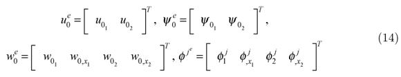
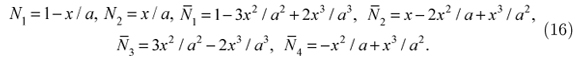
Denote the values of an entity (.) at the nodes 1 and 2 by (.)1 and (.)2 respectively. u0, ψ0, w0, ϕj are interpolated in an element of length a as

with
and

where,
The integrand in the variational Eqn. (12) for the case of static mechanical load can be expressed as
the contribution Te of an element to the integral in Eqn. (12) is obtained as
where,

Defining generalized displacements û, generalised strains  and generalised stress resultants
  as
as
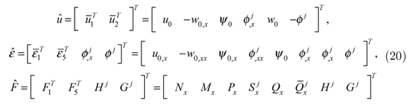
The generalized beam constitutive relation may be expressed as

3.2 Element strains
Defining the element generalized displacement vector Ue as

and using Eqn. (13) the generalized displacements û and strains defined in Eqn. (20) can be related to Ue as

where
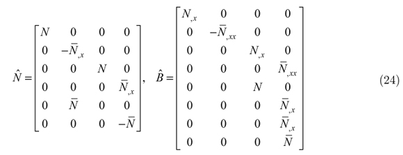
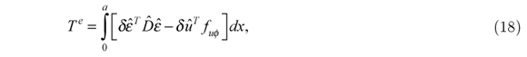
Substituting the expressions for û and from Eqn. (23) into Eqn. (18), Te can be expressed as
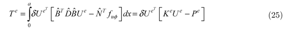
with

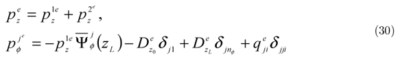
Nx, Mx, Px, and Qx are substituted so that to obtain general equation after integration as:

 , Dz0, DzL, qjiare linearly interpolated in terms of their nodal values,

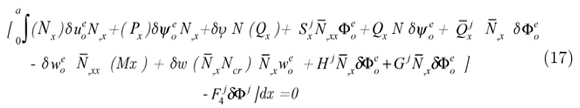
Substituting (24) and (19) into equation (26)yields

and
3.3 FEM for buckling of hybrid beam under axial loading
For buckling of laminated composite beams under axial loading it is assumed that lateral load is zero and the axial forces applied are compressive in nature at the ends. From the variational equation let Nx = Nx - Ncr

where Ncr is the buckling critical load at which buckling occurs, be substituted other terms such as shape functions and primary variables are substituted from equations (13), (14),(15) and (16) to obtain buckling eigen value equation from variational equations

N x, Mx, Px, and Qx are substituted to obtain eigen value problem, after integration

Ncr is an eigen-value of the generalized eigen-value problem .The lowest eigen-value is the critical value of the axial load at which buckling occurs.
KG is the element geometric stiffness matrix
where,

The critical axial strain εcr for buckling under axial load corresponding to critical load is given by εcr= -Ncr /A11 and the critical load Ncr is non-dimensionalised as

The critical axial strain εcr is non-dimensionalised as  =Sε
=Sε
The critical potential ϕcr is non-dimensionalised as cr =
cr =  .
.
The mechanical boundary conditions for a movable simply-supported end, immovable simply-supported (hinged) end, clamped end and free end are taken as follows:
simply-supported end : Nx = 0 (movable) or u0= 0 (immovable), w0 = 0, Mx = 0, Px = 0
clamped end : u0 = 0, w0 = 0, w0,x = 0, Ψ0= 0,
free end : Nx = 0, Vx = 0, Mx = 0, Px = 0 .
4 RESULTS AND DISCUSSIONS
4.1 Validation
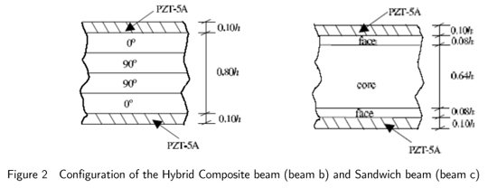
The present 1D-FE formulation of zigzag theory is validated by comparing the results for critical load, and critical strain of the simply-supported beam with the results of Kapuria and Alam (2004) and 2D-FE Abaqus. Results are presented for two types of simply supported hybrid beams of different symmetric laminate configurations (b) and (c) (Fig.2). The beams have two piezoelectric layers of PZT-5A of thickness 0.1h bonded to their elastic substrate on top and bottom surfaces.
The substrate (b) is a graphite-epoxy composite laminate with 4 layers of equal thickness 0.2h with layup [00/900/900/00]. The substrate (c) is a 3-layer sandwich having graphite-epoxy composite faces and a soft core. For a beam of span 'a' and thickness 'h', the thickness parameter S=a/h.
4.2 Numerical Example
For the numerical study, two hybrid beams (b) and (c) with composite and sandwich substrates, respectively are considered (Fig. 2). Both the beams have a PZT-5A layer of thickness 0.1h bonded to the top and bottom of the elastic substrate. The PZT -5A layers have polling in + z direction. The top and bottom of the substrate are grounded. The stacking order is mentioned from bottom.
The composite substrate of beam (b) is a graphite-epoxy (material 1) composite laminate with 4 layers of equal thickness 0.2/7 with lay-up [0º / 90º / 90º / 0º] and the sandwich substrate of beam (c) has graphite-epoxy faces of material 2 and a soft core with thicknesses 0.08h / 0.64h / 0.08h.
The Young's Moduli Yi, Shear Moduli Gij , Poisson's Ratio vij, Piezoelectric Strain Constants dij and Electric Permittivities ηij, are given by:
[Y1, Y2, Y3, G12, G23, G31, v12, v13, v23]
Material 1: [ (181, 10.3, 10.3, 7.17, 2.87, 7.17) GPa, 0.28, 0.28, 0.33]
Material 2: [ (131.1, 6.9, 6.9, 3.588, 2.3322, 3.588) GPa, 0.32, 0.32, 0.49]
Core: [(0.2208,0.2001, 2760, 16.56, 455.4, 545.1)GPa, 0.99, 3x10⁻⁵, 3x10⁻⁵]
PZT-5A:[ (61, 61, 53.2, 22.6, 21.1, 21.1) GPa, 0.35, 0.38, 0.38]
[(d31, d32, d33, d15, d24), (η11, η22, η33 )]
=[(-171, -171, 374, 584, 584)x10-12m/V, (1.53, 1.53, 1.5)x10-8F/m].
4.3 Buckling analysis
The pre-buckling load condition with uniform axial strain  and zero potential i.e. [Ψ(z0)= Ψ(zL)=0] at the top and bottom surfaces is considered. The critical buckling strain and corresponding axial force are denoted as εcr and Ncr respectively.
Ncr is the eigenvalue of the generalized eigenvalue problem .The lowest eigenvalue for n=1 is the critical value of the axial compressive load for which buckling occurs. These eigenvalue problems have been solved for two end conditions of both the beams viz: Clamped-Clamped and Clamped-Free.
4.3.1 Buckling response for clamped-clamped hybrid beam
1D FE and 2D-FE (ABAQUS) buckling results are obtained for the first three modes (i.e. n=1, 2 and 3) and compared for critical buckling load and strain of laminated hybrid beams, beam (b) and beam (c) for clamped-clamped boundary condition. The results are listed in table-5 for beam (b) and table-6 for beam (c).It may be observed that for the same value of S there is little variation in values of critical load and strain for different modes. Further the 1D-FE results are in good agreement with 2D-FE results.
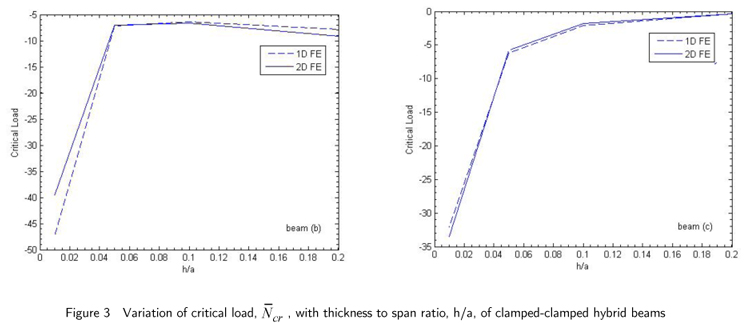
The variation of critical load for first mode (n=1)with thickness to span ratio (h/a) of both the clamped-clamped hybrid beams are shown in Fig.3. The value of the critical load increases as the beams are made thicker for the same span length.
Fig.4 shows the variation of critical load with angle for clamped-clamped hybrid beam, beam (b). The results are shown for span to thickness ratio, S=10.The critical load is maximum for 0 deg and exponentially reduces as the angle increases and become 90 deg. The 1D-FE and 2D-FE plots are in good agreement.
4.3.1 Buckling response for clamped-free hybrid beam
1D FE and 2D-FE (Abaqus) buckling results are obtained and compared for critical buckling load and strain of laminated hybrid beams for clamped-free boundary condition. The results are listed in table-7 and table-8. It may be observed that the 1D-FE results are in good agreement with 2D-FE results.
Fig. 5 shows the variation of critical load for first mode (n=1) with thickness to span ratio (h/a) of fixed-free hybrid beams (b) and (c). The nature of the plot is different from clamped-clamped condition as the critical load values are considerably higher for the fixed beams.
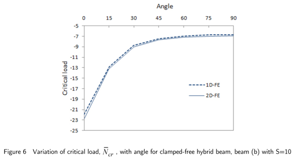
Fig.6 shows the variation of critical load with angle for clamped-free hybrid beam, beam (b) with span to thickness ratio, S=10.The critical load is maximum for 0 deg and exponentially reduces as the angle increases and becomes 90 deg. The 1D-FE and 2D-FE plots are in good agreement.
4 CONCLUSIONS
A new finite element model based on zigzag theory is developed for the buckling analysis of hybrid beams under electromechanical load. The accuracy of the developed 1D-FE model for buckling analysis has been assessed by comparison with the analytical solution for hybrid beam and 2D-FE results obtained using Abaqus for thick, moderately thick and thin hybrid beams for various boundary conditions. The 1D-FE results are in good agreement with 2D-FE results which shows the robustness of the model. The effect of lamination angle on critical buckling load is also substantial.
Received in 14 Feb 2013
In revised form 20 Jun 2013
- Song S.J., Waas, A.M., (1997). Effects of shear deformation on buckling and free vibration of laminated composite beams. Composite Structures, 37(1):33-43.
- Chandrashekhra, K., Bhatia, K. (1993). Active buckling control of smart composite plates-finite-element analysis. Smart Materials and Structures 2:31-9.
- Khdeir, A.A., Reddy, J.N. (1997). Buckling of cross-ply laminated beams with arbitrary boundary conditions. Composite Structures 37:1-3.
- Wang, Q. (2002). On buckling of column structures with a pair of piezoelectric layers. Engineering Structures 24(2):199-205.
- Wang, Q, Quek, ST. (2002). Enhancing 5utter and buckling capacity of column by piezoelectric layers. International Journal of Solids and Structures 39(16):4167-80.
- Thompson, SP, Loughlan, J. (1995). The active buckling control of some composite column structure strips using piezoceramic actuators. Composite Structures 1(32):59-67.
- Kapuria, S., Alam, N. (2004). The Exact two-dimensional piezoelasticity solution for buckling of hybrid beams and cross-ply panels using transfer matrices. Composite Structures 64: 1-11.
- Kapuria, S., Alam, N. (2004). Zigzag theory for buckling of hybrid piezoelectric beams under electromechanical loads. International Journal of Mechanical Sciences 46: 1-25.
- Kamruzzaman, M., Umar, A, Naqvi, S. Q. A. and Siddiqui, N. A. (2006). Effect of composite type and its configuration on buckling strength of thin laminated composite plates. Latin American Journal of Solids and Structures 3: 279-299.
- Kapuria, S., Alam, N. (2005). Nonlinear Zigzag Theory for Buckling of Hybrid Piezoelectric Rectangular Beams under Electrothermomechanical Loads. Journal of Engineering Mechanics 131: 367-376.
- Anas., M., Hussain, I. and Alam, N. (2011). Buckling of Laminated Composite Beams using Zigzag Theory. International journal of advanced engineering sciences and technologies 11: 292 - 296.
- Anas., M., Hussain, I. (2012). Finite Element Modeling and Simulation for Vibration of Symmetric Composite Beams using Zigzag Theory. International Journal of Advanced Scientific and Technical Research 1: 71-78.
- Vo, T., Inam, F. (2012). Vibration and Buckling of Cross-Ply Composite Beams using Refined Shear Deformation Theory. 2nd International Conference on Advanced Composite Materials and Technologies for Aerospace Applications, Wrexham, UK.
- Qiao, P., Shan, L., Chen, F., and Wang, J. (2010).Local Delamination Buckling of Laminated Composite Beams Using Novel Joint Deformation Models. Journal of Engineering Mechanics 136: 541-550.
- Chakrabarti, A., Chalak, H.D., Iqbal, M.A. Sheikh, A.H. (2012). Buckling analysis of laminated sandwich beam with soft core. LAJSS 9: 367 - 381.
- Alam, M.N., Anas, M. (2009). Buckling Analysis of Laminated Composite Beams Using zigzag theory MATLAB and ABAQUS. Proceedings of ICEAE 2009, Bangalore, India.
- Sherwani, S.F.K., Alam, M.N. (2009). Buckling Analysis of Smart Beam Using zigzag Theory and MATLAB, MEMS,ISSS 2009, 14-16 0ct.2009, Kolkata.
- Kapuria, S., Alam, M.N. (2005). A coupled nonlinear zigzag theory for buckling of hybrid piezoelectric beam under electro-thermo-mechanical loads. ASCE J. Engineering Mechanics, 131: 367-376.
- Pandit, M.K., Sheikh, A.H., Singh, B.N. (2008). Buckling of laminated sandwich plates with soft core based on an improved higher order zigzag theory. Thin-Walled Structures 46:1183-1191.
- Matsunaga, H. (1996). Buckling instabilities of thick elastic beams subjected to axial stresses. Computers and Structures 59(5):859-868.
- Matsunaga, H. (2001). Vibration and buckling of multilayered composite beams according to higher order deformation theories. Journal of Sound and Vibration 246(1):47-62.
- Cetkovic, M., Vuksanovic, D. (2009). Bending, free vibration and buckling of laminated composite and sandwich plates using a layerwise displacement model. Composite Structures 88:219-227.
- Aydogdu, M. (2006). Buckling analysis of cross-ply laminated beams with general boundary conditions by ritz method. Composite Science and Technology 66(10):1248-1255.
- Iqbal ,A., Chakrabarti, A. , Chalak, H.D. , Sheikh, A.H. (2011). A new fem model based on higher order zigzag theory for the analysis of laminated sandwich beam with soft core. Composite Structures 93:271-279.
- Moy, S.S.J., Nayak, A.K., Shenoi, R.A. (2005). A higher order finite element theory for buckling and vibration analysis of initially stressed composite sandwich plates. Journal of Sound and Vibration 286:763-780.
- Dawe, D.J., Yuan, W.X. (2001). Overall and local buckling of sandwich plates with laminated faceplates, Part I: Analysis. Computer Methods in Applied Mechanics and Engineering 190(40):5197-5213(17).
- Herbert, A. Mang, Xin Jia, Gerhard H"ofinger. (2012). Finite element analysis of buckling of structures at special prebuckling states. Journal of Theoretical And Applied Mechanics 50(3):785-796.
- Cai, B., Liu, Y., Li, H., Liu., Z. (2011). Buckling analysis of composite long cylinders using probabilistic finite element method. Mechanika 17(5): 467-473.
- Kheirikhah, M.M., Khalili, S.M.R., Fard, K.M. (2012). Buckling Analysis of Soft-Core Composite Sandwich Plates Using 3D Finite Element Method. Applied Mechanics and Materials 105 - 107: 1768-1772.
Publication Dates
-
Publication in this collection
03 Feb 2014 -
Date of issue
Oct 2014
History
-
Accepted
20 June 2013 -
Received
14 Feb 2013