
Abstract
The objective of this study is to investigate a hybrid reinforcement method for concrete beams, which consists of steel rebars and HDPE (high-density polyethylene) uniaxial geogrids, by developing an experimental comparative investigation between utilizing different grades and layers of HDPE uniaxial geogrids as the primary reinforcement or as extra reinforcement to the steel rebars. The experiments for this investigation included 24 reinforced concrete beams in order to provide rich data for the flexural behavior analysis and design approach. For a detailed analysis, strain gauges were connected to steel rebars and HDPE uniaxial geogrids. Analysis of the results shows that the hybrid reinforcement method using steel rebars and HDPE uniaxial geogrids provided greater benefits (such as energy absorption capacity, ductility index, ultimate load, and steel-yield load) and more effective utilization (such as better flexural performance, lower deformation values corresponding to the steel-yield load, and greater benefits to cost ratios) than utilizing HDPE uniaxial geogrids as the primary reinforcement or utilizing the conventional reinforcement of steel rebars. Simple design equations were added to calculate the flexural bending capacity, the necessary HDPE uniaxial geogrids’ grade, and the number of layers utilizing the HDPE uniaxial geogrids as the primary reinforcement or as extra reinforcement to the steel rebars.
Keywords:
Reinforced Concrete Beams; Flexural; Steel Rebars; HDPE; Uniaxial Geogrids; Hybrid Reinforcement; Geogrid Proof-Strain; Simple Design Equations

1. INTRODUCTION
Geogrids are polymers found beneath the materials of geosynthetics and are primarily made from polymeric materials such as polypropylene, polyester, and polyethylene (Saranyadevi et al., 2016Saranyadevi, M.; Suresh, M.; Sivaraja, M. Strengthening of Concrete Beam by Reinforcing with Geosynthetic Materials. Int. J. Adv. Res. Educ. Technol. 2016, 3, 245-251.). They are being utilized as a material for stabilization and material for reinforcement in extraordinary civil works and infrastructures (Maxwell et al., 2005Maxwell, S.; Kim, W.-H.; Tuncer, B.E.; Benson, C.H. Effectiveness of Geo-Synthetics in Stabilizing Soft Subgrades; University of Wisconsin-Madison: Madison, WI, USA, 2005.). Recently, the utilization of geogrids as material for reinforcement has extended toward pavement projects, particularly in the following areas: as materials for reinforcement in asphalt layers, as stabilizing material for unbounded layers (Webster, 1992Webster, S.L. Geogrid Reinforced Base Course for Flexible Pavements for Light Aircraft: Test Section Construction, Behaviour under Traffic, Laboratory Tests, and Design Criteria; National Technical Information Service: Springfield, VA, USA, 1992.), as an interlayer function for pavement overlay solutions (Sharbaf, 2016Sharbaf, M. Laboratory Evaluation of Geogrid-Reinforced Flexible Pavements. Master’s Thesis, University of Nevada, Las Vegas, NV, USA, May 2016.), as a material for shrinkage act reinforcement in Portland cement concrete (Al-Hedad et al., 2017Al-Hedad, S.A.; Bambridge, E.; Muhammad, N.S. Influence of Geogrid on The Drying Shrinkage Performance of Concrete Pavements. Construct. Build. Mater. 2017, 146, 165-174.; Al‐Hedad et al., 2020), as a material for reinforcement in concrete pavement (Al‐Hedad and Hadi, 2020), and as an interlayer function for reducing reflective cracking in the concrete overlays (Al Basiouni Al Masri et al., 2018aAl Basiouni Al Masri, Z.; Daou, A.; Haj Chhade, R.; Chehab, G. Experimental and Numerical Assessment of the Behavior of Geogrid-Reinforced Concrete and Its Application in Concrete Overlays. J. Mater. Civ. Eng. 2018a, 30, 04018332.; Itani et al. 2016Itani, H.; Saad, G.A.; Chehab, G.R. The use of geogrid reinforcement for enhancing the performance of concrete overlays: An experimental and numerical assessment. Constr. Build. Mater. 2016, 124, 826-837.) or for reducing reflective cracking in the asphalt overlays over jointed concrete pavements (Khodaii and Fallah, 2009Khodaii, A.; Fallah, S. Effects of Geo-Synthetic Reinforcement on The Propagation of Reflection Cracking in Asphalt Overlays. Int. J. Civ. Eng. 2009, 7, 131-140.; Walubita et al., 2018Walubita, L.F.; Nyamuhokya, T.P.; Komba, J.; Tanvir, H.A.; Souliman, M.; Naik, B. Comparative assessment of the interlayer shear-bond strength of geogrid reinforcements in hot-mix asphalt. Constr. Build. Mater. 2018, 191, 726-735.). Several studies have been conducted on the utilization of geogrids as a material for reinforcement in Portland cement concrete overlays and thin members (Tang et al., 2018a). Some studies have also been conducted on the utilization of geogrid materials either for the strengthening of concrete slabs and beams (Saranyadevi et al., 2016; Ahmed Shaban, 2019Ahmed Shaban, A.H.G. Strengthening of Reinforced Concrete Slabs Using Different types of Geo-Grids. Int. J. Civ. Eng. Technol. 2019, 10, 1851-1861.), for reinforcement of concrete slabs (Al Qadi et al., 2015Al Qadi, A.N.; Al-Kadi, Q.N.S.; Al-Zaidyeen, S.M. Impact Strength of Oil-Palm Shell on Lightweight Concrete Slabs Reinforced with a Geo-Grid. J. Mater. Civ. Eng. 2015, 27, 04014264.; Tang et al., 2019; Mohamed et al., 2020Mohamed, Ramy N.A.; El Sebai, A.M.; Gabr, Ahmed .-H. 2020. “Flexural Behavior of Reinforced Concrete Slabs Reinforced with Innovative Hybrid Reinforcement of Geogrids and Steel Bars” Buildings 10, no. 9: 161.), or for reinforcement of concrete beams (El Meski and Chehab, 2014El Meski, F.; Chehab, G.R. Flexural Behavior of Concrete Beams Reinforced with Different Types of Geogrids. J. Mater. Civ. Eng. 2014, 26, 04014038.; Shobana and Yalamesh, 2015Shobana, S.; Yalamesh, G. Experimental study of concrete beams reinforced with uniaxial and biaxial geogrids. Int. J. ChemTech Res. 2015, 8, 1290-1295.). The highlights of this research are:
-
Detailed investigation of the flexural behavior of concrete beams when reinforced by HDPE uniaxial geogrids as the primary reinforcement or extra reinforcement to the steel rebars for reinforced concrete beams.
-
Investigation of the value of “HDPE uniaxial geogrids’ proof-strain” for both states of utilizing the HDPE uniaxial geogrids as the primary reinforcement or extra reinforcement to the steel rebars for reinforced concrete beams.
-
Value engineering study on the utilization of HDPE uniaxial geogrids as the primary reinforcement or as extra reinforcement to the steel rebars for reinforced concrete beams.
-
Simple design equations were added to calculate the flexural bending capacity of the concrete beams, the necessary HDPE uniaxial geogrids’ grade, and the number of layers for both states of utilizing the HDPE uniaxial geogrids as the primary reinforcement or as extra reinforcement to the steel rebars for reinforced concrete beams.
-
For future research, the principle of “HDPE uniaxial geogrid pre-stressed concrete beams” was confirmed and recommended. This principle is expected to improve the mechanical properties, minimize plastic deformation, and increase the cost-ratio benefits.
-
The hybrid reinforcement of steel rebars and HDPE uniaxial geogrids is expected to decrease the effect of corrosion on structural behavior, as part of the reinforcement is not affected by corrosion because of environmental acts (HDPE uniaxial geogrids). Therefore, it will also lead to reducing the degree of damage, the influence on the structural behavior, and the time and costs associated with the repair.
2. LITERATURE REVIEW
Aluri and Anand (2015Aluri, A.K.; Anand, Y.B. A Complete Study on Behaviour of Concrete Columns by Using Biaxial Geogrid Encasement. SSRG Int. J. Civ. Eng. 2015, 2, 10-17.) proposed a new reinforcement method for the concrete column using geogrid reinforced steel columns (GRSCs). In this investigation, three types of concrete specimens were tested using an axial loading test. Chidambaram and Agarwal (2014Chidambaram, R.; Agarwal, P. The confining effect of geo-grid on the mechanical properties of concrete specimens with steel fiber under compression and flexure. Constr. Build. Mater. 2014, 71, 628-637.) investigated the confinement effect of geogrids when they were utilized as a reinforcement for reinforced concrete by steel fibers. In this study, concrete specimens were developed and tested by flexural, split tension, and axial compression tests. Sivakamasundari et al. (2017Sivakamasundari, S.; Daniel, A.J.; Kumar, A. Study on Flexural Behavior of Steel Fiber RC Beams Confined With Biaxial Geo-Grid. Procedia Eng. 2017, 173, 1431-1438.) investigated the flexural behavior of concrete beams when reinforced with biaxial geogrids in addition to steel fibers in order to investigate the feasibility of utilizing the biaxial geogrids as a material for shear reinforcement. The experiments involved testing three cylindrical specimens by an axial loading test and testing two concrete control-beams and four concrete beams by a three-point loading test. Chidambaram and Agarwal (2015) investigated the possibility of utilizing geogrids as extra shear reinforcement in concrete beams reinforced by steel fiber. The experiment involved testing 12 concrete beams by a three-point loading test. Meng et al. (2019Meng, X.; Chi, Y.; Jiang, Q.; Liu, R.; Wu, K.; Li, S. Experimental investigation on the flexural behavior of pervious concrete beams reinforced with geogrids. Constr. Build. Mater. 2019, 215, 275-284.) investigated the flexural behavior of porous concrete beams when reinforced with different layers of geogrids placed at different positions. In this study, the concrete beams were tested by a four-point loading test. Digital image correlation and acoustic emission techniques were used to screen strain fields, internal fracture characteristics, and crack propagation. Tang et al. (2018bTang, X.; Higgins, I.; Jlilati, M.N. Behavior of Geogrid-Reinforced Portland Cement Concrete under Static Flexural Loading. Infrastructures 2018b, 3, 41.) investigated the flexural behavior of concrete beams when reinforced by triaxial geogrids. For a close examination of the triaxial geogrids, strain gauges were connected to the triaxial geogrids to monitor the generated strains. The experiment involved testing two concrete control-beams and two concrete beams reinforced by triaxial geogrids by a four-point loading test. Ramakrishnan et al. (2018Ramakrishnan, S.; Arun, M.; Loganayagan, S.; Mugeshkanna, M. Strength and Behaviour of Geogrid Reinforced Concrete Beams. Int. J. Civ. Eng. Technol. 2018, 9, 1295-1303.) investigated the flexural behavior of concrete beams when reinforced by biaxial geogrids as extra reinforcement to steel rebars. The experiment involved testing one concrete control-beam and five concrete beams reinforced by steel rebars and biaxial geogrids by a four-point loading test. Al Basiouni Al Masri et al. (2018bAl Basiouni Al Masri, Z.; Chhade, R.H.; Chehab, G. Experimental Evaluation of The Flexural Behavior of Concrete Beams Reinforced With Stiff Biaxial Geogrid. ISECSJ. 2018b.) investigated the flexural behavior of concrete elements when reinforced by geogrids to propose a geogrid reinforcing configuration dependent on maintaining continuity throughout the concrete section. The experiment involved testing nine concrete beams by a four-point loading test. Chand Beebi and Visweswara Rao (2017Rao, G.A.; Vijayanand, I.; Eligehausen, R. Studies on ductility of RC beams in flexure and size effect. In Proceedings of the 6th International Conference on Fracture Mechanics of Concrete and Concrete Structures, Catania, Italy, 17 June 2017; Volume 2.) investigated the reinforcing of concrete beams by uniaxial or biaxial geogrids, testing one concrete control-beam and six concrete beams reinforced by uniaxial or biaxial geogrids by a four-point loading test. Rakendu and Manoharan (2017Rakendu K.; Manoharan, A. Flexural Behavior of Concrete Beams Reinforced with Biaxial Geogrid. IJERGS. July-August, 2017, 5, 72-83.) investigated the flexural behavior of concrete beams poured by utilizing three different mixes of concrete reinforced by one, three, and five layers of biaxial geogrids. They tested 6 concrete control-beams and 34 concrete beams by a four-point loading test. Ruba Carolin et al. (2020Ruba Carolin C, Mahendran N, and Vijay T J. 2020. “Flexural Performance of Precast Concrete Slab with Gfrp and Geogrid Reinforcement”, International Journal of Recent Technology and Engineering (IJRTE), Volume-9, Issue-1, May 2020, ISSN: 2277-3878.) studied the flexural behavior of a precast concrete slab reinforced by biaxial geogrids and GFRP. The experiment involved testing two concrete slabs by a three-point loading test. Pavithra et al. (2020S. Pavithra, P. Dharaniraj, S. R. Vijay, G. Arumugam, M. Sudakar. “Experimental Investigation on Application of Geogrid in Concrete to Improve its Flexural Strength”, International Journal for Research in Applied Science and Engineering Technology (IJRASET), Volume 8, Apr 2020, Issue IV, Page No: 2140-2145.) studied the applicability of using the biaxial geogrids to increase the flexural behavior of the concrete beams. The experiment involved testing six concrete beams by a four-point loading test. Daou et al. (2020Anas Daou, Ghassan Chehab, George Saad, and Bilal Hamad. 2020. “Experimental and numerical investigations of reinforced concrete columns confined internally with biaxial geogrids”, Construction and Building Materials, Volume 263, 2020,120115, ISSN 0950-0618.) studied the applicability of using the biaxial geogrids as transverse confinement reinforcement instead of the conventional reinforcement steel stirrups in the concrete columns. They tested 14 reinforced concrete columns by monotonic uniaxial vertical compressive load. Vijay et al. (2020T J Vijay, K Rajesh Kumar, R Vandhiyan, Mahender K, and K Tharani. 2020. “Performance of Geogrid Reinforced Concrete Slabs under Drop Weight Impact Loading”, IOP Conf. Series: Materials Science and Engineering (ICRAEM-2020), 9-10, October 2020.) studied the impact behavior of the reinforced concrete slabs by steel rebars and/or biaxial geogrids with different configurations. The experiment involved testing six concrete slabs by impact drop weight test. The key literature review conclusions are:
-
Geogrids can withstand tensile force when they are kept in plain concrete beams, and are a better replacement for steel ties and steel rebars.
-
Geogrids as a reinforcement material for the concrete beams provide greater absorption energy, post-cracking ductility, greater flexural strength, and larger deformation values in accordance with its grade, number of layers, and type in ascending order of triaxial, biaxial, and uniaxial geogrids.
-
Only flexural cracks are formed for all the plain concrete beams, reinforced by geogrids.
-
The confining role of geogrids constitutes a key role in the properties of concrete.
-
Geogrids are also utilized as extra reinforcing material in steel-reinforced beams where requirements of more strength should be met.
-
Crack width is reduced as the grade of geogrids is increased.
-
Both of the post-failure observations of triaxial geogrids and records of strains suggested that no slippage or pullout existed between the concrete and the triaxial geogrids.
-
The reinforcement of circular-shaped geogrids was successful in controlling the opening of cracks.
-
The coarse aggregates’ size should be smaller than the geogrids’ aperture size.
3. MATERIALS
The concrete mix was prepared by utilizing crushed limestone as coarse aggregate, natural sand as fine aggregate, and Portland cement with a grade of 42.5. Table 1 shows the proportions of the concrete mix used in this study. The maximum coarse aggregate nominal size is restricted to 10 mm, which is less than the opening apertures of the HDPE uniaxial geogrids to enable the coarse aggregate to move and fill the gaps between the ribs of the HDPE uniaxial geogrids, to have a better bond between the HDPE uniaxial geogrids and concrete, and to prevent the concrete honeycombing. The concrete admixture of high range water-reducing agent and superplasticizer was used to improve the concrete workability while maintaining a water-to-cement ratio of 0.5. The concrete mixture has a 28-day cube compressive strength (Fcu) of 40 N/mm2.
The reinforcement materials used for concrete beams in the research were steel rebars and HDPE uniaxial geogrids. As per previous studies, the efficiency of geogrids as concrete-beam reinforcement in ascending order according to their type was triaxial, biaxial, and uniaxial geogrids. Furthermore, the uniaxial geogrids provide the most effective utilization when used as extra reinforcement to the steel rebars for concrete slabs (Mohamed et al., 2020Mohamed, Ramy N.A.; El Sebai, A.M.; Gabr, Ahmed .-H. 2020. “Flexural Behavior of Reinforced Concrete Slabs Reinforced with Innovative Hybrid Reinforcement of Geogrids and Steel Bars” Buildings 10, no. 9: 161.). Therefore, the type of geogrid used in this research was HDPE uniaxial geogrids (UG). The properties of the utilized steel rebars according to experimental tests are presented in Table 2. The mechanical and physical properties of the utilized HDPE uniaxial geogrids according to the manufacturer and experimental tests are shown in Figure 1 and Table 3.
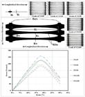
Dimensional characteristics and experimental stress-strain curves of the HDPE uniaxial geogrids.
Characteristics of the utilized HDPE uniaxial geogrids according to the manufacturer and experimental tests.
4. PROGRAM OF EXPERIMENTS
The program of experiments of this research included two groups of 24 concrete beams that all had the following dimensions: length 130 cm, width 15 cm, and depth 20 cm. The reinforcement details of each group’s concrete beams are shown in detail in Figure 2 and Table 4. All concrete beams were reinforced by two 8-mm diameter plain steel rebars at the upper-side reinforcement and 10 8-mm diameter plain steel rebars per meter as stirrups, while the lower-side reinforcement was separated into two groups according to the research program. Group A contained 11 concrete beams, 10 of which were reinforced by different grades and number of layers of HDPE uniaxial geogrids as primary lower-side reinforcement. However, the rest of group A’s concrete beams did not have lower-side reinforcement, which was considered as a concrete control-beam. Group B contained 13 concrete beams, 12 of which were reinforced by two 8-mm diameter plain steel rebars as primary lower-side reinforcement in addition to different grades and number of layers of HDPE uniaxial geogrids as extra lower-side reinforcement, while the rest of group B’s concrete beams were reinforced with two 8-mm diameters plain steel rebars as lower-side reinforcement, which was considered as a concrete control-beam. It is worth noting that HDPE uniaxial geogrids as concrete reinforcement provide better performance when they are combined with a reasonable steel rebar ratio (not a minimum steel rebar ratio) (Mohamed et al., 2020Mohamed, Ramy N.A.; El Sebai, A.M.; Gabr, Ahmed .-H. 2020. “Flexural Behavior of Reinforced Concrete Slabs Reinforced with Innovative Hybrid Reinforcement of Geogrids and Steel Bars” Buildings 10, no. 9: 161.); therefore, this condition was taken into consideration throughout the arrangement of the steel rebars.

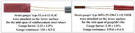
HDPE uniaxial geogrids as a concrete reinforcement perform better when they are tightened prior to the pouring of concrete (Mohamed et al., 2020Mohamed, Ramy N.A.; El Sebai, A.M.; Gabr, Ahmed .-H. 2020. “Flexural Behavior of Reinforced Concrete Slabs Reinforced with Innovative Hybrid Reinforcement of Geogrids and Steel Bars” Buildings 10, no. 9: 161.); therefore, during the connecting of the HDPE uniaxial geogrids’ lower-side reinforcement, they were tightened to ensure that they remained straight during the pouring of concrete. However, for group A, the HDPE uniaxial geogrids reinforcement was did not stay perfectly straight because the steel cages were not steady due to the absence of lower-side steel rebars, while for group B, the HDPE uniaxial geogrid reinforcement was kept straight because the steel cages were steady due to the presence of lower-side steel rebars. During the connecting of the HDPE uniaxial geogrids (UG), we considered locating the middle portion of HDPE uniaxial geogrids’ ribs in the concrete beams’ mid-span to assign the most prone tensile portion of the HDPE uniaxial geogrids’ ribs to the area of high applied tensile stresses during the test. Electrical resistance strain gauges were utilized for monitoring the developed strains in the concrete beams’ lower-side reinforcement to enable an accurate investigation of the HDPE uniaxial geogrids’ application as concrete-beam reinforcement. Figure 3 shows the fixing, isolation, and protection of the strain gauges. Figure 4 shows the types of strain gauges used in this investigation.

5. ARRANGEMENT FOR LOADING METHOD AND TEST SETUP
All of the concrete beams were loaded and tested by a gradually increased four-point loading method by a 500-kN capacity Shimadzu machine until they collapsed in flexure (the protocol of loading is 2 mm for each minute of deformation control). Each load was positioned corresponding to one-third of the beam span in order to provide a zero shear force and maximum bending moment throughout the concrete beams’ middle third. Two roller-supports were utilized, and both of them were positioned at a distance of 7.5 cm from the beam end. To record the deformation values corresponding to the positions where the concentrated loads were positioned and to the mid-span, three vertical linear variable differential transducers (LVDTs) were fixed to each concrete beam. A computerized datalogger was used to monitor and record the measurement data of the strain gauges, the three vertical linear variable differential transducers (LVDTs), and the machine load. Figure 5 shows the setup details of the testing method, the computerized datalogger, and the Shimadzu machine.

6. MECHANISM OF FAILURE AND PATTERNS OF CRACKS
Cracks were formed in the middle third for all concrete beams only. Therefore, only flexural cracks existed, and there were no shear cracks. The failure of the concrete beams was due to the widening of the cracks, the formation of extra cracks in some beams, and the propagation of those cracks from the lower-side surface of the concrete beams (tension zone) up to the upper-side surface of the concrete beams (compression zone) until failure occurred. Figure 6 shows the beams’ crack patterns, and Figure 7 provides some examples of the status of the HDPE uniaxial geogrids’ ribs after the concrete beam failures. For all beams, there was no cutting in the HDPE uniaxial geogrids’ ribs, except for group A’s concrete beams B2 and B3. For concrete beam B1 (the concrete control-beam of group A), only one crack formed and propagated rapidly until failure occurred, while only one crack formed for concrete beams B2 to B8, and two cracks formed in concrete beams B9 to B11 and propagated gradually until failure occurred. For concrete beam B12 (the concrete control-beam of group B), three cracks formed, while three to six cracks formed for concrete beams B13 to B24 and propagated gradually until failure. It is obvious that there is a positive relationship between the number of formed cracks and HDPE uniaxial geogrids’ grades or the number of HDPE uniaxial geogrid layers.


Some examples of HDPE uniaxial geogrids’ ribs status after the failure of the concrete beams.
7. DISCUSSION AND ANALYSIS OF RESULTS
There were some differences in beam behavior between group A and group B in the resuts, so this will be discussed separately for each group.
7.1. Behavior of Load Versus Deformation
For group A, prior to the formation of the first crack, the concrete section bore almost all of the tensile force. The load was directly proportional to the deformation, and the load-deformation relationship was positive linear until the first crack was initiated, then the load increased by between +1 and +3% until it reached the initial-peak load (roughly speaking, the first-crack load is associated with the initial-peak load). As the reinforced concrete sections using minimum reinforcement are brittle structures (Carmona, et al. 2007Carmona, J.R.; Ruiz, G.; Del Viso, J.R. Mixed-mode crack propagation through reinforced concrete. Eng. Fract. Mech. 2007, 74, 2788-2809.), so after the initial-peak load, a sudden drop of the load and a sudden rise of the deformation values occurred due to the inability of the concrete section to bear further tensile force. Then, the tensile force was transferred to the HDPE uniaxial geogrids (the lower-side reinforcement), and the concrete beam bore a further load, with a nonlinear relationship to the deformation values, leading to a new load rise until the load reached the post-peak load, providing extra load capacity and post-cracking ductility. Due to the reduction of the elasticity modulus, the new rise of the load-deformation curve was a slow, incremental one with lower values of the relationship slope. In addition, minor load drops may have occurred due to the yielding or ripping of one or maybe more ribs of HDPE uniaxial geogrids, or because of the slight movement of the transverse bars of HDPE uniaxial geogrids. These minor load drops were followed up with a sudden load rise due to the reallocation of the tensile force on the ribs of HDPE uniaxial geogrids. It is worth highlighting that the presence of upper-side steel rebars in the concrete control-beam B1 provides a post-cracking loading period with a slight post-peak load. Figure 8(A) illustrates the load-deformation curves for group A’s concrete beams. The deformation values corresponding to the first-crack load and the initial-peak load were reduced by between -3 and -68% compared with the concrete control-beam B1. After the initial-peak load, the deformation suddenly disproportionately rose by between +43 and +223%. The deformation values corresponding to the post-peak load rose by between +61 and +123% compared with the concrete control-beam B1. Figure 9(A) shows the deformation values of group A’s concrete beams corresponding to different critical points. Figures 10(A,B) show the deformation patterns of group A’s concrete beams corresponding to the points of initial-peak load and post-peak load.
For group B, prior to the formation of the first-crack, almost all of the tensile force was borne by the concrete section. The first crack formed corresponding to a load value ranging from 0.47 to 0.51 times the ultimate load. After the formation of the first crack, the tensile force borne by the concrete section transferred gradually to be borne by the lower-side steel rebars and the lower-side extra reinforcement by HDPE uniaxial geogrids. The load was directly proportional to the deformation, and the load-deformation relationship was positive linear until the load values reached the first-crack load; then, the load values rose gradually until the lower-side steel rebars reached the steel-yield strain corresponding to load values ranging from 0.58 to 0.62 times the ultimate load. Next, extra cracks formed, leading to a nonlinear load-deformation relationship with lower values of the relationship slope until failure due to the reduction of the elasticity modulus. Throughout the nonlinear load-deformation relationship period, some minor load drops may have occurred due to the yielding or ripping of one or maybe more ribs of HDPE uniaxial geogrids, or because of the slight movement of the transverse bars of HDPE uniaxial geogrids. These minor load drops were followed up with a sudden load rise due to the reallocation of the tensile force on the ribs of HDPE uniaxial geogrids. Figure 8(B) shows the load-deformation curves for group B’s concrete beams. The deformation values corresponding to the first-crack load were reduced by between -15 and -60% compared with the concrete control-beam B12. The deformation values corresponding to the steel-yield load (of the lower-side reinforcement) reduced by between -5 and -58% compared with the concrete control-beam B12. The deformation values corresponding to the ultimate load increased by between +46 and +126% compared with the concrete control-beam B12. Figure 9(B) shows the deformation values of group B’s concrete beams corresponding to different critical points. Figures 10(C,D) show the deformation patterns of group B’s concrete beams corresponding to the points of steel-yield load and ultimate load. It is worth highlighting that the analysis of group B’s load-deformation curves proved that HDPE uniaxial geogrids as concrete reinforcement perform better when they are combined with a reasonable steel rebars ratio (not a minimum steel rebars ratio) and are tightened to ensure they remain straight during the pouring of concrete as recommended by previous research (Mohamed et al., 2020Mohamed, Ramy N.A.; El Sebai, A.M.; Gabr, Ahmed .-H. 2020. “Flexural Behavior of Reinforced Concrete Slabs Reinforced with Innovative Hybrid Reinforcement of Geogrids and Steel Bars” Buildings 10, no. 9: 161.), as this condition does not contain a sudden load drop or a sudden deformation increase, or provide the highest elastic range loads and ultimate capacity loads.
The relationship between the deformation and the HDPE uniaxial geogrids’ grade or the number of HDPE uniaxial geogrids’ layers was analyzed in detail and is presented in Figure 11. For group A, it was a negative relationship until the concrete beam reached the initial-peak load; then, it rapidly turned into a positive relationship until the concrete beam reached the post-peak load. The two HDPE uniaxial geogrids’ layers with a grade of UG120 or UG160 provided more effective utilization, as they had the lowest deformation values corresponding to the concrete beam initial-peak load, while their deformation values corresponding to the concrete beam post-peak load slightly increase when compared with the other lower grades of HDPE uniaxial geogrids, as shown in Figures 11(A,B). For group B, it was a negative relationship until the concrete beam reached the steel-yield load, then it converted gradually, providing a positive relationship corresponding to the concrete beam ultimate load. The first, second, and third HDPE uniaxial geogrid layers with a grade of UG120 or UG160 were more effective, as they had the lowest deformation values corresponding to the steel-yield load (of the lower-side reinforcement), while their deformation values corresponding to the concrete beam ultimate load point had a slight increase compared with the other lower grades of HDPE uniaxial geogrids, as shown in Figure 11(C,D). It is worth noting that the large deformation was allowed during the test until the failure occurred in order to investigate the ultimate strength state of the concrete beams.

Deformation values of each group’s concrete beams corresponding to different critical points.

Deformation patterns of each group’s concrete beams corresponding to different critical points.

The relationship between the deformation and the HDPE uniaxial geogrid grade or the number of HDPE uniaxial geogrid layers, corresponding to different critical points.
7.2. Load and Flexural Strength
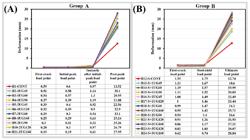
For group A, prior to the formation of the first crack, almost all of the tensile stress was borne by the concrete section due to the HDPE uniaxial geogrids (the lower-side reinforcement) not being perfectly straight and the weak bond at the HDPE uniaxial geogrid-concrete interface until the first crack was initiated. Then, the tensile force moved to the HDPE uniaxial geogrid lower-side reinforcement, the HDPE uniaxial geogrid status became perfectly straight, and the load increased by between +1 and +3% until it reached the initial-peak load (roughly speaking, the first-crack load is associated with the initial-peak load). The non-perfectly straight status of HDPE uniaxial geogrid lower-side reinforcement and the weak bond between HDPE uniaxial geogrids and concrete led to different contributions of HDPE uniaxial geogrid lower-side reinforcement in bearing the tensile force until the concrete beam reached the initial-peak load. This, in turn, led to a weak positive relationship between the first-crack or initial-peak load values and HDPE uniaxial geogrid grade or the number of HDPE uniaxial geogrid layers. In general, utilizing the HDPE uniaxial geogrids as the primary lower-side reinforcement provided a disproportionate increase in the first-crack load and the initial-peak load by between +31 and +63% compared with the concrete control-beam B1. As the minimally reinforced concrete sections are brittle structures (Carmona, et al. 2007Carmona, J.R.; Ruiz, G.; Del Viso, J.R. Mixed-mode crack propagation through reinforced concrete. Eng. Fract. Mech. 2007, 74, 2788-2809.), after the initial-peak load the concrete beam cannot bear further load, resulting in a disproportionate sudden load drop ranging from -70 to -95%. Then, almost all of the tensile force was transferred to the HDPE uniaxial geogrid lower-side reinforcement, and the concrete beam gradually bore a further load until it reached the post-peak load. The values of the post-peak load were recorded, and the values of the post-peak flexural strength were calculated from equation (1). It was obvious that post-peak load and post-peak flexural strength had a positive relationship with the HDPE uniaxial geogrid grade and the number of HDPE uniaxial geogrid layers due to the full contribution of HDPE uniaxial geogrids (the lower-side reinforcement) during the post-peak loading period. The post-peak flexural strength or post-peak load values increased by between +72 and +410% compared with the concrete control-beam B1. It is worth highlighting that, as the HDPE uniaxial geogrid grade and the number of HDPE uniaxial geogrid layers increased, the post-peak load increased, leading to converting the difference between the post-peak load to the initial-peak load gradually from -58 to +31%. Figure 12(A) presents the load values of group A’s concrete beams corresponding to different critical points, and Figure 13 presents the post-peak flexural strength values for each individual concrete beam. The flexural strength of the concrete beams () was calculated using equation (1):
Where P is the post-peak load or the ultimate load (N), L is the distance between the supports (mm), Li is the distance between loads (mm), b is the width of the concrete beam (mm), and d is the depth of the concrete beam (mm).
For group B, prior to the initiation of the first crack, almost all of the tensile force was borne by the concrete section. The lower-side extra reinforcement by HDPE uniaxial geogrids starts to bear the tensile force simultaneously with the lower-side steel rebars due to the HDPE uniaxial geogrids remaining perfectly straight after the concrete pouring, increasing the concrete beams’ ductility, and increasing the number of formed cracks. After the recording of the first-crack load, the steel-yield load, and the ultimate load, and the calculation of the ultimate flexural strength values from equation (1), it was obvious that they had a positive relationship with the HDPE uniaxial geogrid grade and the number of HDPE uniaxial geogrid layers. The first-crack load values increased by between +6 and +48% compared with the concrete control-beam B12. The steel-yield load values of the lower-side reinforcement increased by between +18 and +62% compared with the concrete control-beam B12. The ultimate load and the ultimate flexural strength values increased by between +29 and +95% compared with the concrete control-beam B12. There was a slight reduction in recorded loads values for concrete beams B23 and B24 compared with the loading behavior of the other concrete beams; these two beams had three layers of HDPE uniaxial geogrids lower-side reinforcement, as explained in Table 4. This may have caused a rise in the position of the resultant tensile force, a rise in the position of the cracked section’s neutral axis, and a reduction in the concrete beam’s effective depth, which in turn resulted in decreasing the beams’ loading capacity. Figure 12(B) presents the load values of group B’s concrete beams corresponding to different critical points, and Figure 13 shows the ultimate flexural strength values for each individual concrete beam.
The relationship between the load and the HDPE uniaxial geogrid grade or the number of HDPE uniaxial geogrid layers was analyzed in detail and is presented in Figure 14. For group A, it will be a weak positive relationship until the concrete beam reaches the initial-peak load because of the non-perfectly straight status of HDPE uniaxial geogrids (the lower-side reinforcement) and the weak bond at the HDPE uniaxial geogrid-concrete interface, whereas after the initial-peak load, it becomes a positive relationship until the concrete beam reaches the post-peak load. The two HDPE uniaxial geogrid layers with a grade of UG120 or UG160 were more effective, as they had similar initial-peak load values and high post-peak load values when compared with the other lower grades of HDPE uniaxial geogrids, as shown in Figure 14(A). For group B, it will be a positive relationship during the loading period. The first and second HDPE uniaxial geogrid layers with a grade of UG120 or UG160 provided more effective utilization, as they had greater load values corresponding to the steel-yield load (of the lower-side reinforcement) and greater ultimate load values when compared with the other lower grades of HDPE uniaxial geogrids, as shown in Figure 14(B).


The relationship between the load and the HDPE uniaxial geogrid grade or the number of HDPE uniaxial geogrid layers, corresponding to different critical points.
7.3. Behavior of the Ductility Index
The ductility index is the ratio of the corresponded deformation value to structural element failure (ultimate state) to the corresponded deformation value to the first crack of the concrete or the yield strain of the lower-side steel rebars (Rao et al., 2017Rao, G.A.; Vijayanand, I.; Eligehausen, R. Studies on ductility of RC beams in flexure and size effect. In Proceedings of the 6th International Conference on Fracture Mechanics of Concrete and Concrete Structures, Catania, Italy, 17 June 2017; Volume 2.). For group A, the ductility index was calculated as the ratio of the corresponded deformation value to the post-peak load to the corresponded deformation value to the first-crack load. The calculated values of the ductility index increased by between +69 and +593% compared with the concrete control-beam B1, with a positive relationship to the HDPE uniaxial geogrid grade and the number of HDPE uniaxial geogrid layers, as shown in Figures 15(A,C). For group B, the ductility index was calculated as the ratio of the corresponded deformation value to the ultimate load to the corresponded deformation value to the steel-yield load (of the lower-side reinforcement). The calculated values of the ductility index increased by between +53 and +435% compared with the concrete control-beam B12, with a positive relationship to the HDPE uniaxial geogrid grade and the number of HDPE uniaxial geogrid layers, as shown in Figure 15(B,D). The first, second, and third geogrid layers with a grade of UG120 or UG160 provide more effective utilization, as they had greater values in the ductility index when compared with the other lower grades of HDPE uniaxial geogrid states, as shown in Figures 15(C,D).

The ductility index values and the relationship between the ductility index and the HDPE uniaxial geogrid grade or the number of HDPE uniaxial geogrid layers.
7.4. Behavior of the Energy Absorption Capacity
The capacity of energy absorption was calculated on the basis of the enclosed area by the load-deformation curve (Sivakamasundari et al., 2017Sivakamasundari, S.; Daniel, A.J.; Kumar, A. Study on Flexural Behavior of Steel Fiber RC Beams Confined With Biaxial Geo-Grid. Procedia Eng. 2017, 173, 1431-1438.). The behavior of the tested beams by flexure was also compared with in the form of energy absorption capacity, which was calculated as being the area underneath its load-deformation curves, as in Figure 8. Figures 16(A,B) show the values of the energy absorption capacity and its relationship to the HDPE uniaxial geogrid grade or the number of HDPE uniaxial geogrid layers. For group A, the calculated capacities of the energy absorption increased by between +63 and +381% compared with the concrete control-beam B1 with a positive relationship to the HDPE uniaxial geogrid grade and the number of HDPE uniaxial geogrid layers. For group B, the calculated capacities of the energy absorption increased by between +51 and +121% compared with the concrete control-beam B12, with a positive relationship to the HDPE uniaxial geogrid grade and the number of HDPE uniaxial geogrid layers. The first and second HDPE uniaxial geogrid layers with a grade of UG120 or UG160 provided more effective utilization, as they had greater capacities of the energy absorption capacity when compared with the other lower grades of HDPE uniaxial geogrids, as illustrated in Figure 16(B).
7.5. Load-Strain Behavior of the Lower-Side Reinforcement
The load-strain curves for the lower-side reinforcement of all concrete beams are shown in Figure 17. Figure 17(A) shows the load-strain curves for HDPE uniaxial geogrids (the primary or extra lower-side reinforcement) of all concrete beams (for both groups), while Figure 17(B) shows the load-strain curves for the lower-side steel rebars of group B’s concrete beams. The general arrangement of the lower-side reinforcement, the positions of the strain gauges, the numbering method of HDPE uniaxial geogrid ribs portions, and the numbering method of the HDPE uniaxial geogrid transverse bars are shown in Figure 18.

The values of the energy absorption capacity and the relationship between the energy absorption capacity and the HDPE uniaxial geogrid grade or the number of HDPE uniaxial geogrid layers.


The general arrangement of the lower-side reinforcement, the positions of the strain gauges, the numbering method of HDPE uniaxial geogrid ribs portions, and the numbering method of the HDPE uniaxial geogrid transverse bars.
For group A, all HDPE uniaxial geogrids (the lower-side reinforcement) partly contributed to bearing the tensile force after applying the flexural loads, and its strain values gradually increased to reach strain values ranging from 31 to 170 micro-strain corresponding to the initial-peak load. After that, a sudden increase of +3320% or decrease of -98% occurred for the strain values of the HDPE uniaxial geogrids depending on the position of the first crack related to the position of the HDPE uniaxial geogrid ribs portion R3, where strain gauges were connected. When the first crack formed, the HDPE uniaxial geogrid ribs controlling the crack propagation and its opening led to the elongation of the HDPE uniaxial geogrid ribs. The elongation of the HDPE uniaxial geogrid ribs remained restricted to the portion where the crack reaches the ribs, because the HDPE uniaxial geogrids’ transverse bars were wholly confined by the concrete, maintaining its position and preventing the transmission of the tensile force to the following HDPE uniaxial geogrid ribs portions. Table 5 shows the strain values of the HDPE uniaxial geogrids corresponding to different critical points of group A’s concrete beams.
For group B, the number of formed cracks ranged from 3 to 6, as the presence of lower-side steel rebars contributed to an increase in the concrete beams’ ductility. These cracks were distributed on the geogrid ribs portions R2, R3, and R4, which led to an increase in the contribution of the lower-side extra reinforcement by HDPE uniaxial geogrids in bearing the tensile force. For all concrete beams, the first crack formed in the HDPE uniaxial geogrid ribs portion R3, where the strain gauges were connected. All HDPE uniaxial geogrids (the lower-side extra reinforcement) partly bore the tensile force simultaneously with the steel rebars (the primary reinforcement), after applying flexural loads, and its strain gradually increased to reach strain values ranging from 136 to 2218 micro-strain, corresponding to the steel-yield strain (of the lower-side reinforcement). Then, the strain value of the HDPE uniaxial geogrids gradually increased until it was equal to 20,000 micro-strain, corresponding to a load value ranging from 80 to 100% of the ultimate load. The observed range for the micro-strain values of HDPE uniaxial geogrids corresponding to the steel-yield strain (of the lower-side reinforcement) did not affect the overall performance of the concrete beams, meaning that the tensile force was not equally distributed across the ribs of the HDPE uniaxial geogrids. This, in turn, indicates the existence of numerous possible strain values in the remaining HDPE uniaxial geogrid ribs of the same concrete beam. This also indicated that, if the test for the same concrete beam with the same conditions is repeated, there will be several possibilities of strain values ranging from 136 to 2218 micro-strain, corresponding to the steel-yield strain, because of the random allocation of the tensile force to the HDPE uniaxial geogrid ribs. Therefore, a probabilistic analysis was carried out for the strain values of the HDPE uniaxial geogrids corresponding to the steel-yield load (of the lower-side reinforcement), to have a more constant value, as shown in Figure 19. The results of the probabilistic analysis indicated that the value of the weighted average was equal to 1765 micro-strain, the value of the mean was equal to 1767.93 micro-strain, and the value of the median was equal to 1835.41 micro-strain. The value of the experimental yield strain of the steel rebars was 1770 micro-strain as shown in Table 2, which nearly matched the results of the strain probabilistic analysis of the HDPE uniaxial geogrids, and corresponded to a load value ranging from 58 to 62% of the ultimate load. According to the manufacturer material data sheets of the HDPE uniaxial geogrids, its yield strain value is 130,000 micro-strain (13%), which is significantly greater than the concrete beams’ elastic range, plastic range, and failure limit. Thus, the definition of HDPE uniaxial geogrid proof-strain was considered to be used when the HDPE uniaxial geogrids were utilized as a reinforcement for the concrete beams, to ensure that the reinforced concrete beams by the HDPE uniaxial geogrids would not override the elastic range or an accepted plastic range. Therefore, the HDPE uniaxial geogrid proof-strain value was specified as being equal to the strain value of the steel-yield (which ranged from 1250 (0.13%) to 2500 (0.25%) micro-strain, according to the grade of the steel rebars), when it was used as extra reinforcement to the steel rebars, which maintains the concrete beam within the elastic range or an accepted plastic range. Therefore, the HDPE uniaxial geogrid proof-strain was specified as being equal to 2000 micro-strain (0.2%) when it was used as the primary lower-side reinforcement, which maintains the concrete beam within an accepted plastic range after the initial-peak load, and could be obtained by utilizing the highest grades of HDPE uniaxial geogrids (e.g., UG120, UG160, and higher grades).
Strain values of the HDPE uniaxial geogrids corresponding to different critical points for group A’s concrete beams.

Probabilistic analysis for the strain values of the HDPE uniaxial geogrids corresponding to the steel-yield strain for group B’s concrete beams.
8. VALUE ENGINEERING
The objective of value engineering is to obtain the optimal value and the lowest life-cycle costs by optimization of design principles and by achieving the optimal utilization of construction and building materials (AACE International, 2015). The value of utilizing the material of HDPE uniaxial geogrids as reinforcement for the concrete beams was analyzed by dividing the obtained benefits (energy absorption capacity, ductility index, ultimate load, and post-peak load) by the overall cost of the reinforced concrete beams (concrete, steel rebars, HDPE uniaxial geogrids, and the formwork excepting shoring structure) in Egyptian pounds (LE), as shown in Figure 20. For group A, the first and second layers of HDPE uniaxial geogrids with grades of UG120 or UG160 had an acceptable utilization, as they provided a greater average benefit-to-cost ratio than those for lower grades by +50, +70, and +40% for post-peak load, ductility index, and energy absorption capacity, respectively, as shown in Figures 20(A,B,C). Moreover, as investigated above through the analysis of the load-strain curves for the state of utilizing HDPE uniaxial geogrids as primary reinforcement, the first and second layers of HDPE uniaxial geogrids with grades of UG45, UG60, and UG90 had no effective utilization as the HDPE uniaxial geogrids’ grades and layers (area of ribs’ cross-section) were not sufficient to maintain the concrete beams within an accepted plastic range after the initial-peak load; meanwhile, the HDPE uniaxial geogrids with grades of UG120 or UG160 had an accepted utilization as the HDPE uniaxial geogrids’ grades and layers (area of ribs’ cross-section) were enough to maintain the concrete beams within an accepted plastic range after the initial-peak load. For group B, the first and second layers of HDPE uniaxial geogrids with grades of UG120 or UG160 had effective utilization, as they provided a greater average benefit-to-cost ratio than the ones for lower grades by +17, +33, and +16% for ultimate load, ductility index, and energy absorption capacity, respectively, as shown in Figures 20(D,E,F); meanwhile, the three layers had a lower average benefit-to-cost ratio than the one for two layers by -12 and -10% for ultimate load and energy absorption capacity, respectively, as shown in Figure 20(D,F), except in terms of ductility; the three layers provided a greater average benefit-to-cost ratio than the one for two layers by +46%, as shown in Figure 20(E). The HDPE uniaxial geogrids had optimal utilization when utilized as extra lower-side reinforcement to the steel rebars, particularly for the first and second layers of HDPE uniaxial geogrids with grades of UG120 or UG160, as they were providing benefit-to-cost value and benefit value greater than the other studied states.
9. Design Approach by Quantitative Analysis of First Principles
The tensile force of the upper-side steel rebars and the HDPE uniaxial geogrids (the primary or extra lower-side reinforcement) corresponding to the post-peak load (state of utilizing HDPE uniaxial geogrids as the primary reinforcement) or to the ultimate load (state of utilizing HDPE uniaxial geogrids as extra reinforcement to the steel rebars) were calculated according to the Limit States Design Method of concrete structures, as stated in the Egyptian Code for Design and Construction of Concrete Structures (ECP:203-2018). Therefore, the tensile force of the lower-side steel rebars is equal to its yield force, and the strain of the upper-side of the concrete is equal to 0.3%. Figure 21 shows the design strain and stress diagrams for both states of utilizing the HDPE uniaxial geogrids as the primary reinforcement (group A, corresponding to the post-peak load) or extra reinforcement to the steel rebars (group B, corresponding to the ultimate load).
For the state of utilizing the HDPE uniaxial geogrids as the primary reinforcement, the tensile force of the upper-side steel rebars was greater than its yield force, so it was taken as being equal to its yield force; therefore, the tensile force of the HDPE uniaxial geogrids corresponding to the experimental post-peak load was calculated, and is presented in Table 6. For the state of utilizing the HDPE uniaxial geogrids as extra reinforcement to the steel rebars; the tensile force of the upper-side steel rebars was lower than its yield force, so it was taken as being equal to its calculated force; therefore, the tensile force of the HDPE uniaxial geogrids corresponding to the ultimate experimental load was calculated, and is presented in Table 6.
It is worth highlighting that the HDPE uniaxial geogrids as concrete reinforcement provided greater tensile strength than their experimental tensile strength corresponding to the same strain. This is because, during the experimental tensile test of the HDPE uniaxial geogrids, the transverse bars had free movement, while, as investigated above through the analysis of the load-strain curves, the transverse bars of the HDPE uniaxial geogrids as concrete reinforcement were wholly confined by the concrete, maintaining its position and preventing the tensile force transmission to the following HDPE uniaxial geogrids’ ribs portions, ultimately dividing the total tensile force into the contributing HDPE uniaxial geogrids’ ribs portions to bear it. Figure 22 clarifies the issue in more detail.

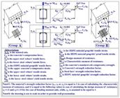
The design strain and stress diagrams for both states of utilizing the HDPE uniaxial geogrids as the primary reinforcement (group A, corresponding to the post-peak load) or as extra reinforcement to the steel rebars (group B, corresponding to the ultimate load).

The decision was made to calculate the concrete beams’ characteristic moment of resistance and design moment of resistance by respecting the defined limits by the Limit States Design Method of concrete structures, as stated in the Egyptian Code for Design and Construction of Concrete Structures (ECP:203-2018); therefore, the tensile force of the upper-side steel rebars is equal to or lower than its yield force, the compressive strain value of the upper-side concrete is equal to 0.3%, the material’s strength reduction factor is equal to 1.5 or 1.15 for calculating the design force in concrete or steel rebars, respectively, and the material’s strength reduction factor is equal to 1 for calculating the characteristic force in concrete or steel rebars. Figure 23 shows the idealized characteristic and design stress-strain curves for the concrete and steel rebar materials. Furthermore, the decision was made to take the tensile force of the HDPE uniaxial geogrids to be its peak tensile force calculated from equation (2) for both states of calculating the characteristic or design moment of resistance. As the HDPE uniaxial geogrids’ strength reduction factor is not stated by any of the concrete structures design codes, it is assumed to be equal to 1 for both states of calculating the characteristic or design tensile force of the HDPE uniaxial geogrids.
Where TG is the peak tensile strength of the HDPE uniaxial geogrids, T is the peak tensile strength (kN/m), W is the strip width (m), and N is the number of layers.

The idealized characteristic and design stress-strain curves for the concrete and steel rebars.
For the state of utilizing HDPE uniaxial geogrids as the primary reinforcement, the characteristic moment of resistance, the design moment of resistance, and its ratios to the experimental moment corresponding to the post-peak load were calculated, as shown in Figure 24. The ratios of the characteristic moment of resistance or the design moment of resistance to the experimental moment corresponding to the post-peak load have unequal values; thus, a probabilistic analysis was conducted to achieve a more constant value, as shown in Figure 25. The experimental moment corresponding to the post-peak load could therefore be calculated from equation (3).
For the state of utilizing HDPE uniaxial geogrids as extra reinforcement to the steel rebars, the characteristic moment of resistance, the design moment of resistance, and its ratios to the experimental moment corresponding to the ultimate load were calculated, as shown in Figure 26. The ratios of the characteristic moment of resistance or the design moment of resistance to the experimental moment corresponding to the ultimate load have unequal values; thus, a probabilistic analysis was conducted to achieve a more constant value, as shown in Figure 27. The experimental moment corresponding to the ultimate load could therefore be calculated from equation (4).
Where TG is the peak tensile strength of the HDPE uniaxial geogrids, FG is the tensile force of the HDPE uniaxial geogrids (kN), T is the peak tensile strength (kN/m), W is the strip width (m), N is the number of layers, MEP is the experimental moment corresponding to the post-peak load for the state of utilizing HDPE uniaxial geogrids as the primary reinforcement, MEU is the experimental moment corresponding to the ultimate load for the state of utilizing HDPE uniaxial geogrids as extra reinforcement to the steel rebars, MCR is the characteristic moment of resistance, and MDR is the design moment of resistance.

Calculations of the characteristic moment of resistance, the design moment of resistance, and its ratios to the experimental moment corresponding to the post-peak load for the state of utilizing HDPE uniaxial geogrids as the primary reinforcement.

Probabilistic analysis for the ratios of the characteristic moment of resistance or design moment of resistance to the experimental moment corresponding to the post-peak load (state of utilizing HDPE uniaxial geogrids as the primary reinforcement).

Calculations of the characteristic moment of resistance, the design moment of resistance, and its ratios to the experimental moment corresponding to the ultimate load for the state of utilizing HDPE uniaxial geogrids as extra reinforcement to the steel rebars.

Probabilistic analysis for the ratios of the characteristic moment of resistance or design moment of resistance to the experimental moment corresponding to the ultimate load (state of utilizing HDPE uniaxial geogrids as extra reinforcement to the steel rebars).
10. CONCLUSIONS AND RECOMMENDATIONS
-
The loading-deformation behavior of the concrete beams when utilizing the HDPE uniaxial geogrids as extra lower-side reinforcement to a reasonable steel rebars ratio (not a minimum steel rebars ratio) being tightened to ensure they remain straight during the pouring of concrete is mostly recommended, as it does not create sudden load drop or increase sudden deformation, and provides the highest elastic range loads, ultimate capacity loads, and normal cracking ductility (not post-cracking ductility).
-
The number of flexural cracks, the initial-peak load, the post-peak load, the steel-yield load (of the lower-side reinforcement), the ultimate load, the flexural strength, the ductility index, the energy absorption, the corresponding deformation to the post-peak load, and the corresponding deformation to the ultimate load all have a positive relationship with the HDPE uniaxial geogrid grade and the number of HDPE uniaxial geogrid layers (area of ribs’ cross-section); meanwhile, the corresponding deformation of the initial-peak load and the corresponding deformation of steel-yield load (of the lower-side reinforcement) have a negative relationship with the HDPE uniaxial geogrid grade and the number of HDPE uniaxial geogrid layers (area of ribs’ cross-section).
-
When utilizing the HDPE uniaxial geogrids as the lower-side primary reinforcement (the studied state of group A), the initial-peak load had a weak positive relationship with the HDPE uniaxial geogrid grade and the number of HDPE uniaxial geogrid layers (area of ribs’ cross-section); meanwhile, the post-peak load had a positive relationship with the HDPE uniaxial geogrid grade and the number of HDPE uniaxial geogrid layers (area of ribs’ cross-section). This is because, when the first crack formed (the end of the initial-peak loading period), the HDPE uniaxial geogrids’ ribs controlling the crack propagation and its opening leads to the elongation of HDPE uniaxial geogrid ribs, which in turn causes the HDPE uniaxial geogrids’ ribs to become tension-stressed (during the post-peak period); therefore, HDPE uniaxial geogrids provide better performance when they are being tension-stressed prior to the concrete pouring. It is therefore highly recommended that the HDPE uniaxial geogrids are tension-stressed prior to the concrete pouring.
-
The ability of HDPE uniaxial geogrids to bear tensile force as a reinforcement for concrete beams is restricted by the parts of the ribs where concrete cracks reach them. Therefore, the HDPE uniaxial geogrids’ performance as a reinforcement of the concrete beams will be improved as the number of concrete cracks increases, spreads, and is widely distributed throughout the tension-zone length of the concrete beam. This state could be obtained by utilizing the higher grades of the HDPE uniaxial geogrids (e.g., UG120, UG160, and higher grades) as the primary reinforcement and will definitely be obtained by utilizing the HDPE uniaxial geogrids as extra reinforcement to the steel rebars.
-
The material yield-strain of the HDPE uniaxial geogrids is 13% (as stated by the manufacturer), which is very far from the concrete beams’ elastic range, plastic range, and failure limit; therefore, the term “HDPE uniaxial geogrids’ proof-strain” was stated to ensure that the reinforced concrete beams by HDPE uniaxial geogrids will not override the accepted behavioral limits of the concrete beams (the elastic range or an accepted plastic range). The HDPE uniaxial geogrids’ proof-strain was specified as being equal to the value of steel rebars’ yielding strain (which range from 0.13 to 0.25% micro-strain, according to the grade of the steel rebars) when it was used as extra reinforcement to the steel rebars, and it was specified as being equal to 0.2% when used as primary reinforcement. The relationship between the load values and HDPE uniaxial geogrid grade or the number of HDPE uniaxial geogrid layers (area of ribs’ cross-section) corresponding to the geogrids’ proof-strain point is a positive relationship for both states of utilizing HDPE uniaxial geogrids as primary reinforcement or as extra reinforcement to steel rebars. Meanwhile, the relationship between the deformation values and HDPE uniaxial geogrid grade or the number of HDPE uniaxial geogrid layers (area of ribs’ cross-section) corresponding to the HDPE uniaxial geogrids’ proof-strain point is a negative relationship for the state of utilizing HDPE uniaxial geogrids as extra reinforcement to the steel rebars, while it is a positive relationship for the state of utilizing the HDPE uniaxial geogrids as primary reinforcement.
-
The utilization of HDPE uniaxial geogrids as primary reinforcement in concrete beams is not accepted for a grade of UG90 or lower, as the HDPE uniaxial geogrid grades and layers (area of ribs’ cross-section) are not able to maintain the concrete beam in an accepted plastic range after the initial-peak load, while a grade of UG120 or higher has an accepted utilization because the HDPE uniaxial geogrid grades and layers (area of ribs’ cross-section) are sufficient to maintain the concrete beam in an accepted plastic range after the initial-peak load point. Moreover, it provided benefits-to-cost values and benefits values greater than those for lower grades. Meanwhile, the HDPE uniaxial geogrids had optimal utilization when utilized as extra reinforcement to the steel rebars, particularly for the first and second layers of HDPE uniaxial geogrids with a grade of UG120 or higher, as they provided greater benefits-to-cost values and benefits values than the other studied states.
-
The benefits of the HDPE uniaxial geogrids as a reinforcement for the concrete beams will be raised by utilizing higher grades or more than one layer. However, the number of layers should be determined by the concrete beam depth, because as the number of layers increases, the position of the resultant tensile force and the position of the cracked section’s neutral axis will be raised, contributing to a reduction in the effective depth of the concrete beam. This, in turn, leads to a reduction in the concrete beam’s load capacity, flexural strength, and energy absorption, while the concrete beam ductility index keeps increasing. In this regard, the higher grades of HDPE uniaxial geogrids (e.g., UG120, UG160, and higher grades) are better utilized as a reinforcement for the concrete beams, because they will provide greater benefits for HDPE uniaxial geogrids with a lower number of layers.
-
HDPE uniaxial geogrids as concrete reinforcement provided greater tensile strength than their experimental tensile strength corresponding to the same strain. This is because, during the experimental tensile test, the transverse bars had free movement, while, as investigated through analysis of the load-strain curves, the transverse bars of the HDPE uniaxial geogrids as concrete reinforcement were wholly confined by the concrete, maintaining their position, and ultimately preventing the transmission of tensile force to the following HDPE uniaxial geogrids’ ribs portions, dividing the total tensile force into the contributing HDPE uniaxial geogrids’ ribs portions to bear it.
-
For the design approach, the HDPE uniaxial geogrids’ tensile force “FG” could be calculated by the equation of “FG= T W N” (where T is the peak tensile strength (kN/m), W is the strip width (m), and N is the number of layers). Therefore, the experimental moment corresponding to the post-peak load “MEP” for the state of utilizing HDPE uniaxial geogrids as the primary reinforcement could be calculated by the equation “MEP = 0.96 MCR = 1.05 MDR”, and the experimental moment corresponding to the ultimate load “MEU” for the state of utilizing HDPE uniaxial geogrids as extra reinforcement to the steel rebars could be calculated by the equation “MEU = 1.11 MCR = 1.25 MDR” (where MCR is the characteristic moment of resistance, and MDR is the design moment of resistance).
11. FUTURE STUDIES
-
Investigate the effectiveness of pre-tensioning the HDPE uniaxial geogrids prior to the concrete pouring to provide HDPE uniaxial geogrid pre-stressed concrete beams. According to the above-mentioned conclusions and recommendations, HDPE uniaxial geogrids are expected to provide better behavior as reinforcement for the concrete beams, if they are tension-stressed prior to the concrete pouring. On the other hand, the material yield-strain of the HDPE uniaxial geogrids is 13%, which is significantly greater than the elastic range, plastic range, and failure limit of the concrete beams; meanwhile, for all concrete beams, the HDPE uniaxial geogrids’ proof-strain has an average value of 0.2%. Therefore, HDPE uniaxial geogrids could be tensioned prior to the concrete pouring, up to a strain percentage of 8% (as an example), to provide HDPE uniaxial geogrid pre-stressed concrete beams and add a new utilization principle of HDPE uniaxial geogrids in structural engineering. This principle aims to improve mechanical properties, minimize plastic deformation, and increase benefit-cost ratio.
-
Investigate the ways to enhance the bonding corresponding to the HDPE uniaxial geogrid-concrete interface.
-
Investigate the effects of dynamic loads on reinforced concrete beams by HDPE uniaxial geogrids.
-
Investigate the effects of cyclic loading on reinforced concrete beams by HDPE uniaxial geogrids.
-
Investigate the effects of span-to-depth ratio on reinforced concrete beams by HDPE uniaxial geogrids.
-
Investigate the shear behavior in relation to reinforced concrete beams by HDPE uniaxial geogrids.
References
- Saranyadevi, M.; Suresh, M.; Sivaraja, M. Strengthening of Concrete Beam by Reinforcing with Geosynthetic Materials. Int. J. Adv. Res. Educ. Technol. 2016, 3, 245-251.
- Maxwell, S.; Kim, W.-H.; Tuncer, B.E.; Benson, C.H. Effectiveness of Geo-Synthetics in Stabilizing Soft Subgrades; University of Wisconsin-Madison: Madison, WI, USA, 2005.
- Webster, S.L. Geogrid Reinforced Base Course for Flexible Pavements for Light Aircraft: Test Section Construction, Behaviour under Traffic, Laboratory Tests, and Design Criteria; National Technical Information Service: Springfield, VA, USA, 1992.
- Sharbaf, M. Laboratory Evaluation of Geogrid-Reinforced Flexible Pavements. Master’s Thesis, University of Nevada, Las Vegas, NV, USA, May 2016.
- Al‐Hedad, A‐A, Hadi, MNS. Effect of geogrid reinforcement on the strains at compressive zone of concrete pavements. Structural Concrete. 2020; 1- 11.
- Al-Hedad, S.A.; Bambridge, E.; Muhammad, N.S. Influence of Geogrid on The Drying Shrinkage Performance of Concrete Pavements. Construct. Build. Mater. 2017, 146, 165-174.
- Al‐Hedad, ASA, Farhan, NA, Zhang, M, Sheikh, MN, Hadi, MNS. Effect of geogrid reinforcement on the drying shrinkage and thermal expansion of geopolymer concrete. Structural Concrete. 2020; 21: 1029- 1039.
- Al Basiouni Al Masri, Z.; Daou, A.; Haj Chhade, R.; Chehab, G. Experimental and Numerical Assessment of the Behavior of Geogrid-Reinforced Concrete and Its Application in Concrete Overlays. J. Mater. Civ. Eng. 2018a, 30, 04018332.
- Itani, H.; Saad, G.A.; Chehab, G.R. The use of geogrid reinforcement for enhancing the performance of concrete overlays: An experimental and numerical assessment. Constr. Build. Mater. 2016, 124, 826-837.
- Khodaii, A.; Fallah, S. Effects of Geo-Synthetic Reinforcement on The Propagation of Reflection Cracking in Asphalt Overlays. Int. J. Civ. Eng. 2009, 7, 131-140.
- Walubita, L.F.; Nyamuhokya, T.P.; Komba, J.; Tanvir, H.A.; Souliman, M.; Naik, B. Comparative assessment of the interlayer shear-bond strength of geogrid reinforcements in hot-mix asphalt. Constr. Build. Mater. 2018, 191, 726-735.
- Tang, X.; Chehab, G.R.; Kim, S. Laboratory study of geogrid reinforcement in Portland cement concrete. In Proceedings of the 6th RILEM International Conference on Cracking in Pavements, Chicago, IL, USA, 16-18 June 2018a; pp. 769-778.
- Ahmed Shaban, A.H.G. Strengthening of Reinforced Concrete Slabs Using Different types of Geo-Grids. Int. J. Civ. Eng. Technol. 2019, 10, 1851-1861.
- Al Qadi, A.N.; Al-Kadi, Q.N.S.; Al-Zaidyeen, S.M. Impact Strength of Oil-Palm Shell on Lightweight Concrete Slabs Reinforced with a Geo-Grid. J. Mater. Civ. Eng. 2015, 27, 04014264.
- Tang, X.; Mohamad, N.; Higgins, J.; Higgins, I. Concrete Slab-on-Grade Reinforced by Geogrids. In Proceedings of the Eight International Conference on Case Histories in Geotechnical Engineering, Philadelphia, PA, USA, 24-27 March 2019.
- Mohamed, Ramy N.A.; El Sebai, A.M.; Gabr, Ahmed .-H. 2020. “Flexural Behavior of Reinforced Concrete Slabs Reinforced with Innovative Hybrid Reinforcement of Geogrids and Steel Bars” Buildings 10, no. 9: 161.
- El Meski, F.; Chehab, G.R. Flexural Behavior of Concrete Beams Reinforced with Different Types of Geogrids. J. Mater. Civ. Eng. 2014, 26, 04014038.
- Shobana, S.; Yalamesh, G. Experimental study of concrete beams reinforced with uniaxial and biaxial geogrids. Int. J. ChemTech Res. 2015, 8, 1290-1295.
- Aluri, A.K.; Anand, Y.B. A Complete Study on Behaviour of Concrete Columns by Using Biaxial Geogrid Encasement. SSRG Int. J. Civ. Eng. 2015, 2, 10-17.
- Chidambaram, R.; Agarwal, P. The confining effect of geo-grid on the mechanical properties of concrete specimens with steel fiber under compression and flexure. Constr. Build. Mater. 2014, 71, 628-637.
- Sivakamasundari, S.; Daniel, A.J.; Kumar, A. Study on Flexural Behavior of Steel Fiber RC Beams Confined With Biaxial Geo-Grid. Procedia Eng. 2017, 173, 1431-1438.
- Chidambaram, R.S.; Agarwal, P. Flexural and shear behavior of geo-grid confined RC beams with steel fiber reinforced concrete. Constr. Build. Mater. 2015, 78, 271-280.
- Meng, X.; Chi, Y.; Jiang, Q.; Liu, R.; Wu, K.; Li, S. Experimental investigation on the flexural behavior of pervious concrete beams reinforced with geogrids. Constr. Build. Mater. 2019, 215, 275-284.
- Tang, X.; Higgins, I.; Jlilati, M.N. Behavior of Geogrid-Reinforced Portland Cement Concrete under Static Flexural Loading. Infrastructures 2018b, 3, 41.
- Ramakrishnan, S.; Arun, M.; Loganayagan, S.; Mugeshkanna, M. Strength and Behaviour of Geogrid Reinforced Concrete Beams. Int. J. Civ. Eng. Technol. 2018, 9, 1295-1303.
- Al Basiouni Al Masri, Z.; Chhade, R.H.; Chehab, G. Experimental Evaluation of The Flexural Behavior of Concrete Beams Reinforced With Stiff Biaxial Geogrid. ISECSJ. 2018b.
- D. Chand Beebi; V.K. Visweswara Rao. Flexural Behavior of Geo-Grid Reinforced Concrete Beams. IJRASET. October, 2017, 5, 7-15.
- Rakendu K.; Manoharan, A. Flexural Behavior of Concrete Beams Reinforced with Biaxial Geogrid. IJERGS. July-August, 2017, 5, 72-83.
- Ruba Carolin C, Mahendran N, and Vijay T J. 2020. “Flexural Performance of Precast Concrete Slab with Gfrp and Geogrid Reinforcement”, International Journal of Recent Technology and Engineering (IJRTE), Volume-9, Issue-1, May 2020, ISSN: 2277-3878.
- S. Pavithra, P. Dharaniraj, S. R. Vijay, G. Arumugam, M. Sudakar. “Experimental Investigation on Application of Geogrid in Concrete to Improve its Flexural Strength”, International Journal for Research in Applied Science and Engineering Technology (IJRASET), Volume 8, Apr 2020, Issue IV, Page No: 2140-2145.
- Anas Daou, Ghassan Chehab, George Saad, and Bilal Hamad. 2020. “Experimental and numerical investigations of reinforced concrete columns confined internally with biaxial geogrids”, Construction and Building Materials, Volume 263, 2020,120115, ISSN 0950-0618.
- T J Vijay, K Rajesh Kumar, R Vandhiyan, Mahender K, and K Tharani. 2020. “Performance of Geogrid Reinforced Concrete Slabs under Drop Weight Impact Loading”, IOP Conf. Series: Materials Science and Engineering (ICRAEM-2020), 9-10, October 2020.
- Carmona, J.R.; Ruiz, G.; Del Viso, J.R. Mixed-mode crack propagation through reinforced concrete. Eng. Fract. Mech. 2007, 74, 2788-2809.
- Rao, G.A.; Vijayanand, I.; Eligehausen, R. Studies on ductility of RC beams in flexure and size effect. In Proceedings of the 6th International Conference on Fracture Mechanics of Concrete and Concrete Structures, Catania, Italy, 17 June 2017; Volume 2.
- AACE International. Skills and Knowledge of Cost Engineering, 6th ed.; Hastak, M., Ed.; AACE International: Morgantown, WV, USA, 2015.
- The Egyptian Housing and Building National Research Center. Egyptian Code for Design and Construction of Concrete Structures (ECP:203-2018).
Edited by
Editor:
Publication Dates
-
Publication in this collection
03 May 2021 -
Date of issue
2021
History
-
Received
02 Mar 2021 -
Reviewed
03 Mar 2021 -
Accepted
11 Mar 2021 -
Published
16 Mar 2021


