Abstract
On the basis of visual origin, shock wave reflection, and jet interference theories, this study aims to (1) divide the process of jet penetration into a hermetic single-cell structure into six parts, (2) establish a theoretical model of a single-cell structure interacting with a jet during its penetration into a structure, and (3) obtain the time expressions of a hermetic single-cell structure interfering with a jet. A residual penetration experiment is conducted to verify the accuracy of the model.
Keywords
shaped charge jet; interference range; single cell structure; anti-penetration performance
1 INTRODUCTION
With the enhancement of the protective ability of new-generation tank armors, the viability and lethality of new tanks have increased dramatically. However, ground and air antitank power and armor piercing/penetration power may still be enhanced in the future. In addition, the current tank armor still has some problems that need to be addressed. Therefore, studying new types of composite armor [1[1] CAO He-quan, ZHANG Guang-ming,SUN Su-jie. Status and Development of Protection Technology of Armored Vehicles[J]. Acta Armamentarii, 2012,33(12):1499-1554.] is important.
To develop a new kind of armor, the interaction mechanism of an armor with a shaped charge jet (SCJ) must be studied. The interaction mechanism of armors, such as the explosive reactive armor (ERA), sandwich composite armor, and ceramic armor with an SCJ, has been studied by scholars. M. Mayseless[2[2] M.Mayseless, Y. Erlich, Y. Falcovitz, G. Rosenberg. interaction of shaped-charge jet with reactive armour. 8thinternational symposium on ballistic,Orlando Florida USA, 1984.
[3] M.Mayseless, E.Marmor, N.Gov ect, Interaction of a shaped charge jet with reactive or passive cassettes,14thinternational symposium on ballistic, Quebec, Canada,1993:439-448-4[4] M.Mayseless, A.Llindenfeld, Stretching, breakup and penetration of perturbed shaped-charge jet, 18thinternational symposium on ballistic, San, Antonio, TX, USA, 1999:1027-1034,] explained the instability of an SCJ after it penetrated an ERA by using the pebble and grazing models. M. Held[5[5] M.Held, M.Mayseless, E.Rototaev. Explosive reactive armor. 17th International symposium on ballistic, Midrand, South Africa,1998:33~46] described the entire physical interaction process of an SCJ with an ERA. G. Luttwak[6[6] L. Gabi and L. Ami. Moving plate perforation analytic model and numerical simulations, 21th International symposium on ballistic, Adelaide, Australian, 2004] established an ERA interference model based on the fact that the SCJ penetration volume is nearly a constant. D. B. Li. et al. [7[7] D.B. Zhu, J. Y. Jing, D. J. Li. Disturbance on an armor-piercing jet caused by an explosive armor. ACTA armamentaria, 1991(01):46~49. (In Chinese)
[8] J. Sun, L. X. Wang, F. W. Liu, Q. Liu. Study on the Rule of the Penetration of the Jet Against Thin Steel Plate. Journal of Projectiles, Rockets, Missiles and Guidance,2006.2(26): 57-60. (In Chinese)
[9] X.J. Shen, X. Q. Ma, J. F. Zeng. Theoretical Calculation of Explosive Driven Metallic Plates for Two Layered Sandwiches. Transaction of Beijing Institute (of Technology. 1994,14(04):341-346. (In Chinese)-10[10] H. W. Liu. Models of Flying-plate Deformation of ERA and its Disturbing on the Shaped Charge Jet. Nanjing University of Science and Technology, Nanjing. 2008. (In Chinese)] explained the process of how ERA plants disturb an SCJ and proposed a theoretical model. P. Pincosy[11[11] P. Philip, P. Peter. Jet propagation through energetic materials, 20th International symposium on ballistic, Orlando, Florida, USA, 2002] considered detonation products as important ERA elements that disturb an SCJ and contributed the fluid mechanics model. N. Gov[12[12] N. Gov, Y. Kivity, D. Yaziv. On the interaction of a shaped charge jet with a rubber Filled metallic cassette .13th International symposium on ballistic, Stockholm, 1992, 95-99.] deemed that the interaction between a sandwich rubber composite armor and an SCJ is similar to that of an ERA. M. Held[13[13] M. Held. Disturbance of Shaped Charge Jets by Bulging Armour. Propellants, Explosive, Pyrotechnics, 2001, 26, 45-57.] analyzed the interference frequency of the Dyneema fiber sandwich composite armor with an SCJ on the basis of experiments. H. Andreas [14[14] H. Andreas, L. Ewa. The role of Kelvin-helmholtz instabilities on shaped charge jet interaction with reactive armours plates Journal of Applied Mechanics. 2010, 77: 051805-1.] considered the rubber in a sandwich rubber composite armor as an inert explosive, which makes the surface plants swell and move, eventually disturbing the SCJ. X. D. Zu[15[15] Zu X, Huang Z, Jia X. Study on Rubber Composite Armor Anti‐Shaped Charge Jet Penetration[J]. Propellants Explosives Pyrotechnics, 2013, 38(5):695-702.] explained the interference mechanism of a rubber composite armor with an SCJ based on stress wave propagation and Kelvin-Helmholtz instability. Many scholars have accepted that the strength of the ceramic armor reduces the penetration ability of the SCJ.
The liquid composite armor is a new kind of composite armor, and research shows that liquid has a good interference effect on the stability of a jet. Thus, studying liquid composite armors is an important research direction with regard to new types of composite armor.
The liquid composite armor is a high-quality composite armor, and research on such armors is currently being conducted here and abroad. However, most studies focused on experimental research and numerical simulation, and only a few explored the mechanism and theoretical research on jet interference after liquid backflow. White and Wahll [16[16] White J J, Wahll J M. Shaped charge jet interactions with liquids[C].Proceedings of the 6th International Symposium on Ballistics. Orlando, Florida, USA: International Ballistics Society, 1981:305-311.] studied the penetration of a jet in a liquid-filled hermetic structure and found that liquid can interfere with jet stability. Lee [17[17] Lee E S, Oh K H, Song S Y. Penetration of particulated shaped-charge jet into water[C]. High-Speed Photography and Photonics: International Congress. International Society for Optics and Photonics, 1995:975-981.] explored the penetration process of jet particles in water through high-speed photography and X-ray experiments. Held [18[18] Held M, Huang N S, Jiang D, Chang C. C. Determination of the crater radius as a function of time of a shape charge jet that penetrates water[J]. Propellants, Explosives, Pyrotechnics, 1996, 21: 64-69.] modified Szendrei equations and obtained the reaming equations of jet penetration in water through high spatial and temporal resolution and profile streak technology. Through an experiment, X. D. Zu[19[19] Zu X D, Huang Z X, Xiao Q Q, Zhu C S, Qian J P. Study on Cell Structure Liquid Composite Armor Subjected to Shaped Charge Jet Impact[C]. Proceedings of the 28th International Symposium on Ballistics, Atlanta, Georgia, USA, September 22-26,2014:1325-1332.] found that a structure filled with polyether polyol honeycomb has good antijet penetration, and he analyzed the influence of the molecular weight of polyether polyol on the performance of jet penetration. On the basis of visual origin theory, Z. Y. Gao.[20[20] Zhen-Yu Gao,Zheng-Xiang Huang,Min Guo,Xu-dong Zu, Q Q Xiao, X Jia. Theoretical Study of a Diesel-Filled Airtight Structure Unit Subjected to Shaped Charge Jet Impact[J].Propellants,Explosives,Pyrotechnics.2016,41:62-68.] established a mechanical model of a diesel oil-filled hermetic structure interfering with a jet, obtained the interfered velocity range expressions of a jet, and verified the theory model through an X-ray experiment. M.A. Biot[21[21] M.A. Biot. Theory of propagation of elastic waves in a fluid-satutated porous solid.I. Low-frequencyrange. Journal of the Acoustical Society of America,1956, 28(02):168-178.,22[22] Zienkiewicz, T. Shomi. Dynamic behavior of satutated porous media: the generalized Biot formulation and its numerical solution[J].International Journal for numerical and analytical methods in geomechanics,1984,8(01):71-96] discussed the propagation property of stress wave in porous media and contributed a simulation model. O.C. Zienkiewi[23[23] Held M, Kozhushko A A. Radial crater growing process in different materials with shaped charge jets[J]. Propellants, Explosives, Pyrotechnics, 1999, 24(6): 339-342.] modified nonlinear coupled models of a shock wave in porous media with and without liquid.
With penetration into a liquid-filled, single-cell structure and SCJ as the research topic, this paper analyzes runaway jet parameters and the interference performance of a liquid-filled, single-cell structure with a jet. Furthermore, it calculates the penetration ability of a runaway jet and verifies the accuracy of the model through a residual penetration experiment.
2. Theory model
This study divides the interaction between a full-of-liquid single-cell structure into six stages, namely, penetration into target, initial reaming, shock wave propagation and reflection, liquid radial convergence, jet interference by liquid, and runaway jet penetration stages.
Shock wave is formed when jet penetrates liquid. A shock wave is a conically diffused spherical wave, and its propagation direction is perpendicular to the wavefront along its normal direction. When the jet starts to penetrate the liquid layer, the short reaming stage is reached. The initial shock wave quickly reaches the sidewall of a single structure that reflects the shock wave. Reflected wave propagation prevents the reaming process of the subsequent jet. If the surface stress of the reflected shock wave is greater than the expansion stress, then the liquid enters a radial convergence process. Then, the entire penetration channel from the bottom to the top starts to converge closed because when the shock wave propagates along the wavefront, the reflected shock wave forms at the sidewall first and then reaches the lower part of the liquid layer. Therefore, the liquid layer at the lower part starts to converge closed first until the entire penetration channel achieves complete convergence.
To simplify the calculation and formula derivation, this paper makes the following assumptions:
The length and diameter ratio of the inner cavity of the container is relatively large so that the reflected shock wave from the sidewall has no effect at the bottom of the full-of-liquid container.
If the diameter of the inner cavity of the container is small and the shock wave propagation distance is short and propagates in low attenuation coefficient liquid, then the speed and intensity of shock wave propagation is considered unchanged.
The radial and axial pressures of initial reaming are equal.
In a short time, only one action of the shock wave on container wall and jet is considered.
The initial speed is the speed of jet contacting liquid.
Figure 1 shows the shock wave propagation path when jet impacts on liquid.
2.1 Penetration into target
According to assumption (1), when jet impacts on diesel liquid, the liquid is squeezed horizontally and moves because the liquid is incompressible. On the basis of one-dimensional wave theory, when the liquid hits the wall of the container bound by the impact plane, left-pass shock wave spreads in the liquid and right-pass shock wave spreads in the wall. According to the continuity condition, liquid and wall have the same particle velocity in the impact plane, and according to Newton’s third law, they both have the same stress. By applying momentum conservation to the shock wavefront, we obtain
where is the density of the liquid, is the sound velocity of the liquid, is the density of the container wall, is the sound velocity of the container wall, and is the impact velocity.
From Formula (1), we can derive the particle velocity and stress p
Particle velocity is considered v 1 after the first impact between the liquid and the container wall. When the left-pass wave in the liquid propagates to the left free surface of the liquid, reflection occurs. At the same time, the particle velocity of the reflected wave becomes double that of the incident wave on the free surface. Then, the relation will be
where is the particle velocity after reflection. , and then by integrating (2) into (4), we can derive the expression of
The impedance of the liquid is much smaller than that of the container wall. Thus, we obtain .
The movement direction of the liquid is away from the container wall. Thus, when the liquid stress is larger than the jet reaming stress under the effect of shock wave, liquid convergence occurs and interferes with jet.
2.2 Initial reaming stage
The velocity of jet is greater than the sound velocity of liquid. Thus, the velocity of disturbed liquid exceeds the propagation velocity of disturbance, producing shock wave in the liquid. The shock wave is a conically diffused spherical wave in the medium, and the propagation direction of shock wave is along its normal direction. The behavior of jet in the liquid is analyzed in two directions. We consider that the shock wave is composed of two parts. In one part, the normal direction of the wavefront is the same as the jet movement direction. In the other part, the shock wave propagates at a certain angle in the horizontal direction.
Energy conservation and momentum conservation are applied on the shock wavefront as follows:
represent the pressure, velocity, and density of the penetrated liquid before and after the wavefront. m is the unit mass. is the propagation velocity of the shock wave.
Suppose the liquid before the wavefront provides the jet with resistance and is equal to ,
The initial velocity of the liquid is zero before being disturbed, that is, . The shock wave and particle velocity of the penetrated liquid can be expressed as[18[18] Held M, Huang N S, Jiang D, Chang C. C. Determination of the crater radius as a function of time of a shape charge jet that penetrates water[J]. Propellants, Explosives, Pyrotechnics, 1996, 21: 64-69.,24[24] Meyer s M A.Dy namic Behavior of Materials [M].Translated by Huang F. Beijing:National Defence IndustryPress, 2006:79-82 .]
At the same time, the penetration process is considered as follows when under balance:
is the penetration velocity of jet.
From expressions (6) to (10), we can obtain the liquid density, pressure, and particle velocity after the wavefront
Assuming that the density of liquid is instantaneously changed under the effect of shock wave, the liquid density is after the wavefront. According to assumption (4), we can construct the Bernoulli equation.
From (11) to (14), we can derive the penetration equation of the jet
From (11) to (15), we can derive penetration velocity of jet units
where is the movement velocity of jet, is the Hugoniot parameter of liquid, is the density of liquid, is the density of jet, is the sound velocity in liquid, and is the radial propagation velocity of the shock wave.
When the penetration velocityis reduced to C0, the penetration equation will be
At this time, the velocity of jet units will be
2.3 Shock wave propagation and reflection stage
The propagation velocity of shock wave in diesel oil is approximately equal to
From the Bernoulli equation, the stagnation pressure under different pore diameters is the sum of dynamic pressure and static pressure at the pore wall, where static pressure is the liquid pressure after the wavefront. Thus, the stagnation pressure will be
Axial pressure is equal to initial reaming pressure . Then, we will obtain
The product of radial reaming pressure and reaming area is a constant value, then
where p is the radial reaming pressure.
From expressions (20) to (22), we can obtain
Then, the reaming velocity of the pore wall will be
where , , , r is the radius of jet.
At the same time, the relationship between the radius of reaming and time can be expressed as a differential equation
By integrating (23) into (24) and separate variables, we derive
The pore size equals the radius of the jet. By integrating expression (26), we obtain
By transforming expression (27), we can derive the relationship between the radius of the pore and the time
Given the thick wall of the cell and the short effect time of the shock wave, we can ignore the effect of deformation of cell wall on shock wave. According to continuity conditions, we derive
For waves with frequency of ù, the pressure can be expressed as
The related particle velocity will be
When , and , we can obtain
The problem can be idealized as the solution to a one-dimensional shock wave propagating in diesel oil. Where the wave impedance of diesel oil is 1,485,675 kg/, the wave impedance of aluminum and steel is 14,758,560 and 14,758,560 kg/, respectively. If the wall is relatively thick and its movement is small, then we can ignore its effect on shock wave.
According to expression (3), we can calculate the reflected pressure on the sidewall when the jet interacts with liquid.
2.4 Liquid radial convergence stage
In the horizontal direction, shock wave is considered to reflect when impacting on the container wall. Shock wave is strong at this time. According to the characteristic of shock wave, a sudden change occurs before and after the shock wavefront, and the state is discontinuous. In addition, the horizontal size is small. Therefore, the shock wave is considered unchangeable in the process of propagation. When the liquid converges, the closing pressure will be
and the closing velocity will be
The propagation path of the shock wave satisfies the relationship
From expressions (35), (19), and (28), we can solve , .
is the time when the liquid particles of the reaming wall radial converge to the surface of the jet and can be expressed as follows
2.5 Interfered jet and runaway jet analysis
The length of the undisturbed jet (runaway jet) is
Subsequent jets are disturbed by different intensities. The penetration ability can be calculated according to the visual origin method.
where L is the penetration depth; H is the standoff; is the distance from the top to the bottom of the liner; and are the head and rear velocity of the jet, respectively; and and is the density of the jet and the target, respectively.
3. Experiment verification
3.1 Standard shaped charge experiment
The standard shaped charge was used in this study for the following reasons: to increase the universality of the study and simplify the calculation of the protection, cost, and protection thickness coefficients. Moreover, the standard-shaped charge is often used in related studies. The 56 mm diameter standard shaped charge (Figure 2) has a shaped charge copper liner with 0.8 mm thickness and JH-2 explosive (comprise 95% RDX and 5% TNT) mass of 203 g without a conical charge shell cover. The DOP experiments were set as shown in Figure 3 to measure the standard SCJ parameters, with the 80 mm standoff and velocity sensors set at the top and the bottom of the standoff cylinder to measure the time of the SCJ tip through the standoff. The 8# flash detonator was used to detonate the SCJ. The experiment results are shown in the Table 1.
The result showed that the quality of this batch of shaped charge is stability. When the standoff is 80mm the average penetration depth was 184.3 mm, with a relative error of approximately 3%. When the standoff is 80mm the average penetration depth was 221.3 mm, with a relative error of approximately 3%. The SCJ had good consistency, and the inlet diameter was almost the same as the outlet diameter. In the DOP experiments, the velocity of the SCJ tip was 6,470 m/s.
The jet tip and tail velocities were simultaneously measured using a multi-channel X-ray system. The double flash X-ray exposures of the SCJ at 30 and 50 ìs after initiation are shown in Figure 4. The magnification of the X-ray exposures was 2.0. Thus, the jet tip velocity was 6,453 m/s and that of the tail was 1,179 m/s. A comparison between the velocity of the SCJ tip obtained from the X-ray exposures and that measured from the DOP experiments shows that the relative error did not exceed 0.3%.
Double flash X-ray exposures of the SCJ at 30 and 50 µs after initiation (all dimensions in mm)
2.2 Structure parameters of full-of-liquid cell
The material of the full-of-diesel-oil liquid hermetic structure and the witness target is 45# steel. The liquid in the single-cell structure is 0# diesel oil. Table 2 shows the mechanical properties of 45# steel and material parameters of 0# diesel oil. Figure 5 shows a physical map of the full-of-diesel-oil hermetic structure.
Figure 6 shows the positional relationship between the projectile and the target in the experiment. The distance of the bottom of the liner and the cell structure is 80 mm and is 330 mm between the bottom of the liner and the surface of the witness target. The thickness of the witness target is 200 mm. Figure 7 shows the site layout of the residual penetration experiment. A foam board is used in digging a hole to fix the full-of-diesel-oil single structure. Two groups of steel ingots support the foam board, and the standard shaped charge without a case is supported by a standoff tube. The standoff tube can fix the position of the standard shaped charge and ensure that the jet penetrates the cell structure vertically. The witness target used in the experiment is a stack of two 100-mm-high 45# steel ingots.
3.3 Experimental results
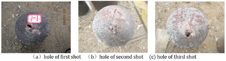
3.3.1 Hole formed in witness target
Figure 8 shows the hole formed in the witness target after the jet penetrates the full-of-liquid single structure. The jet particles among the hole are evident in the figure because when the jet penetrates full-of-liquid single structures, radial convergence and backflow liquid can continuously interfere with the jet, thereby reducing the stability of the jet. At the same time, part of the splashing liquid will exert a radial force on the jet, thereby causing jet particles to deviate from the original path of penetration. Finally, jet particles scatter near the hole formed in the witness target.
3.3.2 Residual penetration
Table 3 shows the residual penetration of the jet effect on the witness target after the residual penetration has been measured and counted.
Table 3 shows that the residual penetration depth is 158.3 mm, with a 5.7% error compared with the theoretical calculation result of 159.4 mm; this error is within the allowable range. Thus, the theoretical calculation result has good agreement with the experiment result, thereby showing that the theoretical model of jet penetration in a hermetic single structure is valid. In addition, the theoretical calculation results of maximum and minimum velocity are 2,695 and 3,351 m/s, with errors of 3.3% and 3.2% compared with the experiment results. The experiment results show that the residual head velocity and residual penetration of jet are 6,038 and 169 mm, with errors of 2.1% and 5.6%, respectively. In sum, the errors are all small and within the allowable range. Therefore, the theoretical model is reliable.
4. Conclusions
This paper improves and perfects the theoretical model of jet penetrating a full-of-liquid single-cell structure. The theoretical results are in good agreement with the experimental results. The following findings were obtained:
The theoretical model [6[6] L. Gabi and L. Ami. Moving plate perforation analytic model and numerical simulations, 21th International symposium on ballistic, Adelaide, Australian, 2004] of jet penetrating a full-of-liquid single structure is improved from the three aspects of shock wave propagation direction, propagation path, and reflection mode. The range of jet interference velocity is more accurate and the error is smaller in the theoretical model than the experiment results.
The normal convergence of liquid can effectively affect the stability of the jet. In other words, the liquid composite armor is a new type of high-quality armor. The theory of cell relative structure establishes the foundation for cell structure liquid composite armors that will be developed in the future.
Acknowledgements
This research was supported by the National Natural Science Foundation of China (Grant No.11072115).
References
-
[1]CAO He-quan, ZHANG Guang-ming,SUN Su-jie. Status and Development of Protection Technology of Armored Vehicles[J]. Acta Armamentarii, 2012,33(12):1499-1554.
-
[2]M.Mayseless, Y. Erlich, Y. Falcovitz, G. Rosenberg. interaction of shaped-charge jet with reactive armour. 8thinternational symposium on ballistic,Orlando Florida USA, 1984.
-
[3]M.Mayseless, E.Marmor, N.Gov ect, Interaction of a shaped charge jet with reactive or passive cassettes,14thinternational symposium on ballistic, Quebec, Canada,1993:439-448
-
[4]M.Mayseless, A.Llindenfeld, Stretching, breakup and penetration of perturbed shaped-charge jet, 18thinternational symposium on ballistic, San, Antonio, TX, USA, 1999:1027-1034,
-
[5]M.Held, M.Mayseless, E.Rototaev. Explosive reactive armor. 17th International symposium on ballistic, Midrand, South Africa,1998:33~46
-
[6]L. Gabi and L. Ami. Moving plate perforation analytic model and numerical simulations, 21th International symposium on ballistic, Adelaide, Australian, 2004
-
[7]D.B. Zhu, J. Y. Jing, D. J. Li. Disturbance on an armor-piercing jet caused by an explosive armor. ACTA armamentaria, 1991(01):46~49. (In Chinese)
-
[8]J. Sun, L. X. Wang, F. W. Liu, Q. Liu. Study on the Rule of the Penetration of the Jet Against Thin Steel Plate. Journal of Projectiles, Rockets, Missiles and Guidance,2006.2(26): 57-60. (In Chinese)
-
[9]X.J. Shen, X. Q. Ma, J. F. Zeng. Theoretical Calculation of Explosive Driven Metallic Plates for Two Layered Sandwiches. Transaction of Beijing Institute (of Technology. 1994,14(04):341-346. (In Chinese)
-
[10]H. W. Liu. Models of Flying-plate Deformation of ERA and its Disturbing on the Shaped Charge Jet. Nanjing University of Science and Technology, Nanjing. 2008. (In Chinese)
-
[11]P. Philip, P. Peter. Jet propagation through energetic materials, 20th International symposium on ballistic, Orlando, Florida, USA, 2002
-
[12]N. Gov, Y. Kivity, D. Yaziv. On the interaction of a shaped charge jet with a rubber Filled metallic cassette .13th International symposium on ballistic, Stockholm, 1992, 95-99.
-
[13]M. Held. Disturbance of Shaped Charge Jets by Bulging Armour. Propellants, Explosive, Pyrotechnics, 2001, 26, 45-57.
-
[14]H. Andreas, L. Ewa. The role of Kelvin-helmholtz instabilities on shaped charge jet interaction with reactive armours plates Journal of Applied Mechanics. 2010, 77: 051805-1.
-
[15]Zu X, Huang Z, Jia X. Study on Rubber Composite Armor Anti‐Shaped Charge Jet Penetration[J]. Propellants Explosives Pyrotechnics, 2013, 38(5):695-702.
-
[16]White J J, Wahll J M. Shaped charge jet interactions with liquids[C].Proceedings of the 6th International Symposium on Ballistics. Orlando, Florida, USA: International Ballistics Society, 1981:305-311.
-
[17]Lee E S, Oh K H, Song S Y. Penetration of particulated shaped-charge jet into water[C]. High-Speed Photography and Photonics: International Congress. International Society for Optics and Photonics, 1995:975-981.
-
[18]Held M, Huang N S, Jiang D, Chang C. C. Determination of the crater radius as a function of time of a shape charge jet that penetrates water[J]. Propellants, Explosives, Pyrotechnics, 1996, 21: 64-69.
-
[19]Zu X D, Huang Z X, Xiao Q Q, Zhu C S, Qian J P. Study on Cell Structure Liquid Composite Armor Subjected to Shaped Charge Jet Impact[C]. Proceedings of the 28th International Symposium on Ballistics, Atlanta, Georgia, USA, September 22-26,2014:1325-1332.
-
[20]Zhen-Yu Gao,Zheng-Xiang Huang,Min Guo,Xu-dong Zu, Q Q Xiao, X Jia. Theoretical Study of a Diesel-Filled Airtight Structure Unit Subjected to Shaped Charge Jet Impact[J].Propellants,Explosives,Pyrotechnics.2016,41:62-68.
-
[21]M.A. Biot. Theory of propagation of elastic waves in a fluid-satutated porous solid.I. Low-frequencyrange. Journal of the Acoustical Society of America,1956, 28(02):168-178.
-
[22]Zienkiewicz, T. Shomi. Dynamic behavior of satutated porous media: the generalized Biot formulation and its numerical solution[J].International Journal for numerical and analytical methods in geomechanics,1984,8(01):71-96
-
[23]Held M, Kozhushko A A. Radial crater growing process in different materials with shaped charge jets[J]. Propellants, Explosives, Pyrotechnics, 1999, 24(6): 339-342.
-
[24]Meyer s M A.Dy namic Behavior of Materials [M].Translated by Huang F. Beijing:National Defence IndustryPress, 2006:79-82 .
-
Available online: August 28, 2018
Publication Dates
-
Publication in this collection
2018
History
-
Received
12 Mar 2018 -
Reviewed
07 Aug 2018 -
Accepted
20 Aug 2018