Abstract
The efficiency of steel fibers for shear strength of reinforced concrete beams is assessed. Four beams were evaluated: control consisted of one beam without any steel fibers and three beams with reinforced concrete with steel fibers. All beams were reinforced for shear strength by a minimum reinforcement rate. The influence of fiber content added to concrete, at 0.5%, 0.8% and 1.0%, and the possibility of partial or total replacement of conventional shear reinforcement (stirrups) by steel fibers were evaluated. Results showed a significant increase in ductility and stiffness of the beams with steel fibers and, consequently, changes in the failure mode were observed, of shear (control beam) to flexure behavior (beams with steel fibers).
Keywords:
Shear; steel fibers; beams; experimental analysis
-
Nomeclature
- k = scale factor
- ρl = longitudinal reinforcement
- ρw = Transversal reinforcement
- fFtuk = residual resistance characteristic to last limit state
- fctk = resistance characteristic to tensile strength
- fc = resistance to concrete strain
- fFts = residual resistance to service limit state
- b = beam width
- d = effective depth ofthe beam
- Asw = area of two legged stirrup
- sw = uniform spacing of the stirrups
- fywd = yield strength of the steel stirrups
- fFts = residual resistance to service limit state
- fR1 = residual tensions to flexure strain CMOD1 = 0.5 mm
- fR3 = residual tensions to flexure strain CMOD1 = 2.5 mm
- Cf = fiber content
- lf = fiber length
- df = fiber diameter
- lf/df = fibre aspect ratio
- Vflex = flexural resistance
- mR = resisting moment of the beam
- a = shear span
- a/d = shear span-effective depth ratio
1 INTRODUCTION
Yoo et al. (2016YOO, D., BANTHIA, N., YANG, J., YOON, Y. (2016). Size effect in normal- and high-strength amorphous metallic and steel fiber reinforced concrete beams. Construction and Building Materials 121, 0950-0618.), Khan et al. (2016KHAN, S., KHAN, R. A., KHAN, A. R., ISLAM, S. (2016). Strength Gain Analysis of Polypropylene Fiber Reinforced Concrete. International Journal of Scientific Research in Science, Engineering and Technology. 2394-4099.) and other authors insist that plain concrete is a fragile material with low flexure capacity and with restricted resistance and tenacity to strain (Satpute et al., 2016SATPUTE, P. C., KULKARNI, V. P., KANDEKAR, S. B. (2016). Mechanical Properties of M25 Grade Concrete by Using Steel and Glass Fibers. International Journal of Engineering Science and Computing, Vol 6, 2321-3361.). New technologies have been introduced to supplement several mechanical restrictions, such as reinforced concrete where reinforcement is provided by ductile material bars (steel, carbon or glass fiber) or, more recently, by discrete fibers placed in the concrete. Mobasher et al. (2015MOBASHER, B., YAO, Y., SORANAKOM, C. (2015). Analytical solutions for flexural design of hybrid steel fiber reinforced concrete beams. Engineering Structures 100, 0141-0296.) highlights the great viability of steel-fiber-reinforced concrete (SFRC), since the reinforcement mechanism provided by the fibers improves strain, flexure, shearing, fatigue, energy absorbing capacity, cracking control and ductility. It should be enhanced that several research works have also demonstrated the contribution of steel fibers, either as sole reinforcement or as hybrid composition (fiber+stirrups) for shear strength. In their tests of 49 beams, Narayanan and Darwish (1987NARAYANAN, R., DARWISH, I. Y. S. (1987). Use of steel fibers as shear reinforcement. ACI Structural Journal, 0889-3241.) reported that steel fibers increased large load and improvements in shearing for all types of fibers. Shear failure of a beam without stirrups is sudden and brittle; and since shear strengths may vary significantly from the values predicted by design equations most of the current design guidelines (ACI Committee, 2011ACI Committee (2011). Building code requirements for structural concrete and commentary.) require a minimum amount of shear reinforcement. According to Jain and Singh (2016JAIN, K., SINGH, B. (2016). Deformed steel fibres as minimum shear reinforcement - An investigation. Structures - Elsevier, V 7, 126-137.), the minimum shear reinforcement requirements in concrete beams have been extensively investigated in the past, giving rise to the hybrid use of steel fibers with a minimum amount of shear reinforcement, in order to assist the bearing capacity of the beams. In research developed by Ding (2012DING, Y. (2012). Investigations into the relationship between deflection and crack mouth opening displacement of SFRC beam. Elsevier, Construction and Building Materials, V 25, 0950-0618.), shear resistance increased in proportion to the addition of fibers in the concrete, coupled to the fact that the combined use of fibers and stirrups increased the concrete´s capacity in energy absorption and tenacity when compared to reinforced concrete (RC) beams. You et al. (2010YOU, Z., DING, Y., NIEDEREGGER, C. (2010). Replacing Stirrups of Self-Compacting Concrete Beams with Steel Fibers. Transactions of Tianjin University. Vol 16, 1006-4982.) discuss the assets of hybrid reinforcement and underscore advantages in terms of resistance and ductility for fiber content (Cf)>25 kg/m3 (≈ 0.33%). Besides the above aspects, MacGregor and Wight (2012)MACGREGOR, J.G., WIGHT, J.K. (2012). Reinforced concrete - Mechanics and design. 4a ed., Upper Saddle River, Ed. Prentice Hall. highlight the fragile trait of failure mode by shearing which, according to You et al. (2010) and Tahenni et al. (2016TAHENNI, T., CHEMROUK, M., LECOMPTE, T. (2016). Effect of steel fibers on the shear behavior of high strength concrete beams. Construction and Building Materials 105, 0950-0618.), may be avoided by SFRC. In fact, when properly dosed, fibers may transform the failure mode from fragile (shearing) to ductile (flexure). Additionally, Yoo et al. (2017)YOO, D., YUAN, T., YANG, J., YOON, Y. (2017). Feasibility of replacing minimum shear reinforcement with steel fibers for sustainable high-strength concrete beams. Engineering Structures, 147, 207-222. investigated the feasibility of eliminating the minimum shear reinforcement in reinforced high-strength concrete beams with a fiber content of 0.75%, concluding that the minimum shear reinforcement for reinforced SFRC beams can be efficiently eliminated. Yoo and Yang (2018)YOO, D., YANG, J. (2018). Effects of stirrup, steel fiber, and beam size on shear behavior of high-strength concrete beams. Cement and Concrete Composites. emphasized the conclusions previously presented. The present study assesses the performance of steel fibers in beam shear strength with a minimum transversal reinforcement rate (ρw,min), to verify the possible replacement of conventional transversal reinforcement (stirrups) for a reinforcement mechanism provided by the use of steel fibers, with modification of the failure mode, from a brittle one (without steel fibers) to a ductile (SFRC beams). Experimental program comprised four beams (150x300x2700 mm3): a control beam (without fibers) and three SFRC beams, with fiber content at 0.5%, 0.8% and 1.0%. Beam characteristics, instrumentation plan, characterization of materials and resistance estimates are provided. Through the results obtained, beams with the addition of steel fibers present more ductile behavior to the point of having their rupture mode changed from brittle to ductile, and obtaining a favorable influence from the fibers on the tenacity of the beams in CRFA. In addition, the reinforcing mechanism provided by the steel fibers causes stress relief in the transverse reinforcement, which allows for the reduction of ρw, including when working with a minimum transversal reinforcement ratio (ρw=ρw,min).
2 NORMATIVE RECOMMENDATIONS (MODEL CODE, 2010MODEL CODE (2010). CEB-FIP model code 2010 - Final draft. Lausanne, Switzerland: Thomas Thelford.)
This section discusses the calculation model used to determine the shear and flexural strength of reinforced concrete beams with the addition of steel fibers, proposed by Model Code (2010)MODEL CODE (2010). CEB-FIP model code 2010 - Final draft. Lausanne, Switzerland: Thomas Thelford. design guidelines, as is presented below:
2.1. Shear resistance
According to Model Code (2010)MODEL CODE (2010). CEB-FIP model code 2010 - Final draft. Lausanne, Switzerland: Thomas Thelford., shear resistance of beams in reinforced concrete with steel fibers (VRd) is the sum of portions of reinforced concrete with steel fibers (VRd,f) and transversal reinforcement (VRd,s), respectively (Equations 1 and 2).
where,
And
Amounts fR1 and fR3, derived from notched prism flexure assay, are respectively residual tensions to flexure strain corresponding to fissure aperture CMOD1 = 0.5 mm and CMOD3 = 2.5 mm. However, in current study, residual tensions were defined according to Equations 4 and 5, following Moraes Neto et al. (2013)MORAES NETO, B.N., BARROS, J.A.O., MELO, G.S.S.A. (2013). A model for the prediction of the punching resistance of steel fibre reinforced concrete slabs centrically loaded. Construction and Building Materials 46, 0950-0618., since results were lower than expected.
2.2. Flexural resistance
Due to beam support and loading conditions, flexural resistance (Vflex) is given by,
Flexure model, suggested by Model Code (2010)MODEL CODE (2010). CEB-FIP model code 2010 - Final draft. Lausanne, Switzerland: Thomas Thelford., is employed to determine the rate of the moment. Figure 1 shows F and y, respectively strength and its lever arms. Quota z amounts to 0.9·d and fFtuk is given in Equation 3.
3 EXPERIMENTAL PROGRAM
This article presents the characteristics of the beams tested, with special emphasis on: longitudinal and transverse reinforcement; instrumentation; the test system; and the concrete and steel characterization of the reinforcement. It is noteworthy that this experimental study was carried out entirely within the Civil Engineering laboratory at the Federal University of Pará, Brazil.
3.1. Characteristics of the beams
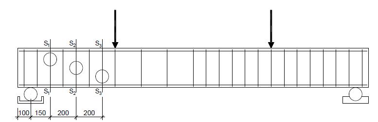
The experimental program comprises four beams (150x300x2700 mm3), or rather, a control beam (without fibers) and three SFRC beams. The shear span-effective depth ratio (a/d) was approximately 2.4. The variable fiber content (Cf) in SFRC beams was evaluated at 0.5% (≈40 kg/m3), 0.8% (≈60 kg/m3) and 1.0% (≈80 kg/m3). The influence of the amount on the beams´ shearing behavior could be analyzed because of this interval, once according to Mobasher et al. (2015MOBASHER, B., YAO, Y., SORANAKOM, C. (2015). Analytical solutions for flexural design of hybrid steel fiber reinforced concrete beams. Engineering Structures 100, 0141-0296.), interval 0.5% < Cf < 1.0% was sufficient to provide high ductility to concrete. The screwed hooked-end steel fiber (3D Dramix 65/60 BG) presented length (lf) and diameter (df), respectively equal to 60 mm and 0.9 mm, form factor (lf/df) = 65, tensile modulus 1.16 MPa and elasticity modulus ≈210 GPa. For concrete compressive strength, fc=30 MPa (28 days old) was chosen since resistance class represents practical design situations. A asymmetrical distribution for transversal reinforcement was adopted (Figure 2), adequately defining the area to be analyzed. This reinforcement rate in the analyzed region is the minimum reinforcement rate prescribed by Model Code (2010), ρw = ρw,min = 0.08% (≈ ø4.2 c/ 200 mm), whilst ρw = 2∙ρw,min (≈ ø4.2 c/ 100 mm) was applied in the span opposite to the analyzed area. Three bars, 12.5 mm diameter (ρflex = 0.91%), were used as flexure reinforcement.
3.2. Instrumentation
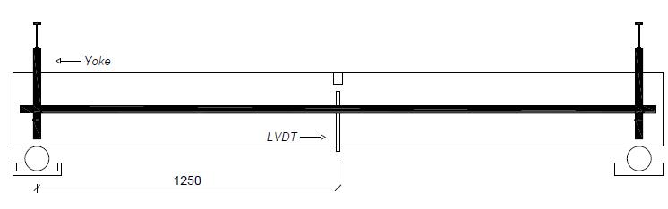
Strains on flexure and shear reinforcements were monitored by Resistance Electrical Extensometers (EER, EXCEL Sensors, PA-06-125AA-120L). Figure 2 shows the four monitored positions whose registration evaluated load levels and identified possible relaxation of the flexure and shear reinforcements. Displacements were measured by Linear Variable Differential Transformer (LVDT) placed at the midspan of the beams (Figure 3). Barros et al. (2011BARROS, A. R., GOMES, P. C. C., BARBOSA, A. S. R. (2011). Steel fibers reinforced self-compacting concrete - behavior to bending. Ibracon Structure and Materials Journal 4, 1983-4195.), Ding (2012DING, Y. (2012). Investigations into the relationship between deflection and crack mouth opening displacement of SFRC beam. Elsevier, Construction and Building Materials, V 25, 0950-0618.) and Fritih et al. (2013FRITIH, Y., VIDAL, T., TURATSINZE, A., PONS, G. (2013). Flexural and Shear Behavior of Steel Fiber Reinforced SCC Beams. KSCE Journal of Civil Engineering, 1976-3808.) also adopted the above methodology. LVDT was fixed to the beam by Yoke, establishing displacement register according to the beams´ longitudinal axis. Further, the device was used to minimize the negative influence of possible defaults due to concentrated loads on the supports.
4 MATERIALS AND METHODS
Cement, large and small pebbles and water were respectively at 1:2.66:2.34.0.5. A superplastificant additive was employed to maintain constant a/c, without changing the workability of the concrete. Dosage was employed to mold the beams and the respective specimens, and three cylinders (100 mm diameter and 200 mm height) and three prisms (150x150x550) mm3 were used. Mortar at 61% was sufficient to avoid exudation/segregation. Further, quality of the fresh concrete was practically invariable, regardless of the fibers´ volume. There was a specimen decrease of 100 mm±20 mm in the slump test, following recommendation by Brazilian Association of Techinal Standards, ABNT NBR NM 67 (ABNT, 1998ABNT NBR NM 67 (1998): Concrete - Determination of consistency by discounting the cone´s trunk.). Large aggregates comprised class 0 rolled pebble, maximum diameter of 9.5 mm and fine module of 6.71, as recommended by ABNT NBR NM 248 (ABNT, 2003aABNT NBR NM 248 (2003a): Pebbles - Determination of granulometric composition. ). Specific mass was 2.63 kg/m3, following ABNT NBR NM 53 (ABNT, 2009ABNT NBR NM 53 (2009): Large pebbles - Determination of specific and apparent mass and water absorption.), and unit mass was 13.74 kg/m3, following ABNT NBR NM 45 (ABNT, 2006ABNT NBR NM 45 (2006): Pebbles - Determination of unit mass and volume of empty spaces.). Small aggregates comprised mid-sized sand particles, fine module 2.7, mass unit at 2.83 kg/m3 and specific mass at 2.45 kg/m3, following ABNT NBR NM 52 (ABNT, 2003bABNT NBR NM 52 (2003b): Small pebbles - Determination of specific mass and apparent specific mass.).
4.1. Beams’ manufacturing
The instrumentation of steel bars occurred prior to the mounting of the reinforcements (Figure 4a). Further, curing of beams and specimens started immediately after the hardening of the concrete surface under similar conditions. Humid-type curing was achieved when sections were covered with cloth and wetted constantly (at intervals of ≈7 hours) for 14 consecutive days. Different types of concrete were prepared in a 400 L-mixer in which the volume required to mold the beam and their respective specimens were produced. Concrete was placed manually in the molds and density was achieved by immersion vibrator. Molds for beams and prisms were manufactured with 10 mm-thick plywood (Figure 4b) smeared with release agent (Denver Imper) for easy unmolding.
4.2. Characteristics of materials
4.2.1. Concrete
The compressive strength of the concrete (fc,exp) followed recommendations by ABNT NBR ISO 1920-3 (ABNT, 2004ABNT. NBR ISO 1920-3 (2004): Testing of concrete- Part 3: Making and curing test specimens.). Three cylinders (diameter=100 mm; height=200 mm) were used for each type of concrete. Mean compression strength (fcm,exp) was evaluated by statistical indexes, arithmetical averages (fcm,exp or εfcm,exp), standard deviation (DP) and coefficient of variation (CV), displayed in Table 1 (synoptic view). Table 1 reveals that dispersion of results for fcm,exp were adequate, with CV ∈ [5.5-10.0]%. Consequently, fcm,exp satisfactorily represents mean compressive strength of the concrete. The concrete´s theoretical compressive strength mean, fcm,theo=30 MPa, was compared to experimentally-obtained rates where the ratio fcm,exp/fcm,theo=1.41 for concrete C0.8. The latter rate contrasted significantly to theoretical expectations, since it was different from the others, fcm,exp/fcm,teo≈1.0. Further, Table 1 shows the parameter fcm,SFRC/fcm,SC, revealing low significant influence of the fibers in compression strength. In fact, fcm,SFRC/fcm,SC≈1.2 for concrete C1.0, excluding result of concrete C0.8. Contrastingly to tensile analysis, the evaluation of the relationship between the strain of control concrete and SFRC concretes demonstrated the fiber´s capacity to transform the simple concrete into a more ductile material. In fact, εfcm,SFRC/εfcm,SC ∈[1.25-1.50].
4.2.2. Residual flexural strength of SFRC
Three notched prisms (150x150x550 mm3) were experimentally flexured to assess post-fissure behavior of concretes C0, C0.5, C0.8 and C1.0, following recommendations by RILEM (2002)RILEM TC 162-TDF. (2002). Test and design methods for steel fibre reinforced concrete: Uniaxial tension test for steel fibre reinforced concrete, Recommendation. Materials and Structures, v. 34, p. 3-6.. Behavior was evaluated by residual strengths fRi (i=1-4), defined by relationship load-displacement or load-CMOD. Only load-displacement (f-δ) and fRi, rates, derived from f-δ, were monitored in current study, defined according to displacements δ1= 0.46 mm, δ2=1.31 mm, δ3=2.15 mm and δ4=3.0 mm, as suggested by RILEM (2002)RILEM TC 162-TDF. (2002). Test and design methods for steel fibre reinforced concrete: Uniaxial tension test for steel fibre reinforced concrete, Recommendation. Materials and Structures, v. 34, p. 3-6.. Table 2 gives a summary of residual strength, precisely with strength fLP, which corresponds to the concretes´ proportionality limit. According to RILEM, fLP represents the highest strength rate within f-δ between interval δ ∈ [0.00-0.05] mm. Strengths were determined by Equation 7:
Where, P corresponds to load monitored; L=500 mm is the prism´s true span; b=150 mm is the width; hsp is the height of the prism at the notch section (hsp=150-25=125 mm). Displacement δ was monitored by LVDT locked to the prism by a yoke fixation device.
Flexure mechanism in notched prisms and mean results - strength-displacement ratio (mean rates).
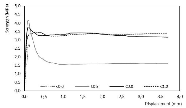
Although Figure 5 demonstrates that the linear response of f-δ was not affected by the addition of steel fibers, strength fLP revealed significant changes for the ratio fLP,SFRC/fLP,SC ∈ [1.20-1.45]. As expected, two distinct behavior standards among the different types of concrete were registered within the post-failure of f-δ: post-failure with the softening of concrete C0.5 and the behavior of concretes C0.8 and C1.0, characterized by tensile maintenance of the post-peak phase.
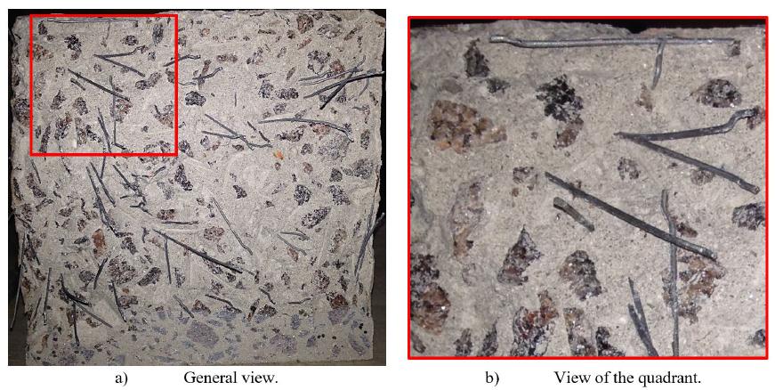
There is a similar behavior between concretes C0.8 and C1.0 (Figure 5), even though there is a difference in fiber consumption between these materials, due to a greater resistance to compression of concrete C0.8 (fc≈40 MPa) when compared to C1.0 (fc≈30 MPa). This event reveals the influence of compression resistance on the fiber-concrete interaction, providing the best anchorage conditions to fibers and thus favoring the integrity of the specimen (crack control) and the maintenance of transference of strength in advanced cracking stages (improved capacity). In-depth analysis comprised counting the number of fibers (Nf) in the transversal section (Ap) broken from the prisms, with Ap = (150x125) mm2, disregarding the notch section. Counting was performed through photos (Figure 6). Figure 7 summarizes counts and registers the division of section Ap in nine quadrants to make easier the counting of the fibers. Barros and Antunes (2003BARROS, J. A. O., ANTUNES, J. A. B. (2003). Experimental Characterization of the Flexural Behaviour of Steel Fibre Reinforced Concrete According to RILEM TC 162-TDF Recommendations. RILEM TC 162 TDF Workshop.) furnish other data on counting methodology. According to Krenchel (1964KRENCHEL, H. (1964). Fibre reinforcement: theoretical and practical investigations of the elasticity and strength of fibre-reinforced materials. Copenhagen, Akademisk Forlag.), the number of fibers estimates fiber disposition (FD). Since concrete was poured into beam and specimen molds by a poorly rigorous and controlled method, or rather, manually, the event should be taken into account. In fact, unfavorable disposition conditions impair the mechanical characteristics of the materials and, consequently, the beams´ structural performance. Table 3 evaluates the disposition factor, where FD is defined according to Nf/Ap, Af and Cf, as follows FO=Nf∙Af∙(Ap∙Cf)-1. In the equation, Af is the transversal section of the steel fiber.
Results in Table 3 demonstrated that disposition rate oscillated at approximately 0.30±0.02. However, studies by Dupont and Vandewalle (2005DUPONT, D., VANDEWALLE, L. (2005). Distribution of steel fibres in rectangular sections. Cement and Concrete Composites 27, 0958-9465.) and Lee and Kim (2010LEE, C., KIM, H. (2010). Orientation factor and number of fibers at failure plane in ring-type steel fiber reinforced concrete. Cement and Concrete Research 40, 0008-8846.) show that in normal usage conditions, or rather, without the damaging interference of fiber disposition, FD≈0.5, as a rule. Further, a significant number of fibers parallel to the prisms´ breaking plane is registered (Figure 6), highlighting current discussion. It may be asked whether these circumstances have somewhat affected residual resistance fRi (i=1 up to 4) registered unsatisfactorily as from f-δ given in Figure 5.
4.2.3. Steel bars’ mechanical properties
The mechanical properties of steel bars which constitute the beams´ reinforced concrete have been established by ABNT NBR ISO 6892 (ABNT, 2013ABNT NBR ISO 6892 (2013): Metallic materials - Starin assay. Part 1: Method for assay at room temperature.). Five samples of each diameter (ø4.2, ø6.3 and ø12.5 mm) were tested for axial tensile strength. Discharge tensions and deformations and, consequently, the elasticity module (Es), were extracted from the average stress-strain relationship. Rates for the elasticity module of bars 4.2 mm, 6.3 mm and 12.5 mm were 201.5 GPa, 264.9 GPa and 200.1 GPa, respectively.
4.2.4. The effective uptake of fibers
So that the effective uptake of fibers (Cf,exp) in steel-fiber-reinforced concrete (SFRC) beams could be confirmed, three controls or testimonies (cylinders with a diameter of 100mm; beam height and width measured 150mm) were extracted from each beam, after the assays, according to recommendations by ABNT NBR 7680 (ABNT, 2015ABNT NBR 7680 (2015): Concrete - Extraction, preparation, assay and analysis of control in concrete structure. Part 1: Resistance to axial compression.) and ACI (ACI Committee, 2010ACI Committee (2010): Guide for Obtaining Cores and Interpreting Compressive Strength Results.) for controls´ extraction and assay. The site of controls along the beam followed the plan given in Figure 8. Analysis in different sections and positions along the beam´s longitudinal axis was possible to evaluate the distribution of fibers throughout the beams´ height and length. The volume of each control (VT) and the weight of total fibers in control (Pf) were assessed so that the real uptake of beam fibers (Cf,exp) could be analyzed. True fiber uptake could be given by the ratio Pf/VT in [kg/m3] or [%]≈[kg/m3]/80.
Volume VT was retrieved by methodology based on Archimedes´ Principle, recommending the evaluated of VT (VT=VL-ΔV) by difference in volume (ΔV) registered when control is immerged in a liquid (water) of known volume (VL). So that Pf could be calculated, controls were crushed till all fibers were free of the concrete mass; fibers were then removed from the concrete mass by a magnet and weighed on a precision scale (AD50k with 1.0 g precision). Table 4 gives results of Cf,exp analysis. Table 4 reveals that true uptake of fibers in SFRC beams did not differ significantly with regard to height and length of the specimens, with CV ∈ [3.5-12.0]%. Response reveals that launch/density method employed in current assay, namely, launching by hand and density by immersion vibrator, do not impair fiber dispersion in the concrete mass when done correctly. Relationship Cf,exp/Cf,teo showed that theoretical expectations for fiber consumption were met successfully in the experimental program. Only concrete C1.0 demonstrated a slightly higher fiber uptake to that planned.
5 EXPERIMENTAL RESULTS
The section presents and discusses results on beam monitoring. The relationship load-displacement, the mobilization of the longitudinal and transversal reinfircements, cracking patterns and beam resistance estimates were investigated.
5.1. Load-Displacement relationships
Current analysis registered displacement in the midspan of the beam only. Load-displacement (Figure 9) and amounts that characterize the relationship (Table 5) were the parameters for the analysis of the load-displacement relationship (V-δ). The ratio Vu,CRFA/Vu,CS (quotient between the beams failure loads in SFRC and SC= simple concrete = V0) is employed for the measurement of the beams´ resistance capacity, Vu,CRFA/Vu,CS≈1.40, regardless of the consumption of fibers used in current analysis. Besides resistance increase, current scenario reveals that the structural behavior of the SFRC beams is slightly variable even with different fiber contents. Kang et al. (2012KANG, T. H., KIM, W., MASSONE, L. M., GALLEGUILLOS, T.A. (2012). Shear-Flexure Coupling Behavior of Steel Fiber-Reforced Concrete Beams. ACI Structural Journal 109, 0889-3241.) and Conforti et al. (2013CONFORTI, A., MINELLI, F., PLIZZARI, G.A. (2013). Wide-shallow beams with and without steel fibres: A peculiar behavior in shear and flexure. Composites: Part B 51, 1359-8368.) reported a similar behavior. Reinforcement conditions of the beams, ρflex=0.91% and ρw=ρw,min=0.08%, should be borne in mind for an explanation of the event. The rate of the longitudinal reinforcement (ρflex) for beam V0 (without fibers) showed the mobilization of transversal forces (cutting force) which were not opposed by the mechanism of the transversal resistance of the section (ρw). As a consequence, the beam failure due to shearing. However, in the case of SFRC beams, the hybrid resistance (fibers+stirrups) warranted the maintenance of transversal forces and prevented failure by shearing. Consequently, normal stress, derived from flexure, were the beams´ critical condition.
In the failure of SFRC beams, the ρflex rate intensified strain in the compressed area and brought about the failure by flexure through the crushing of concrete. Characterization tests confirmed the poor influence of Cf on the concrete compressive strength, with a maximum of 19% increase in resistance (Table 1). The above has been reported in V-δ response (Figure 9) when the minimum interference of Cf in the structural performance of SFRC beams was reported. Contrastingly to ratio Vu,SFRC/Vu,SC, with similar responses for SFRC beams, the ratio in between δu,SFRC/δu,SC (δu = displacement, referring to failure load of SFRC and SC beams) was opposite, with δu,SFRC/δu,SC ∈ [2.5-4.0] (Table 5). The above condition reveals two important aspects, or rather, the influence of steel fiber for beam ductility. In fact, δu,SFRC/δu,SC increased when fibers were added to the concrete. Fiber capacity, when dosed adequately, modified the failure mode from shear to flexure, corroborating conclusions by You et al. (2010YOU, Z., DING, Y., NIEDEREGGER, C. (2010). Replacing Stirrups of Self-Compacting Concrete Beams with Steel Fibers. Transactions of Tianjin University. Vol 16, 1006-4982.), Minelli et al. (2014MINELLI, F., CONFORTI, A., CUENCA, E., PLIZZARI, G. (2014). Are steel fibres able to mitigate or eliminate size effect in shear?. Materials and Structures 47. 1871-6873.) and Tahenni et al. (2016TAHENNI, T., CHEMROUK, M., LECOMPTE, T. (2016). Effect of steel fibers on the shear behavior of high strength concrete beams. Construction and Building Materials 105, 0950-0618.). Therefore, V-δ showed that SFRC beams (V0.5, V0.8 and V1.0) had a predominantly ductile behavior, where the control beam, V0, revealed a fragile behavior. Since SFRC capacity absorbs deformation energy, beam´s tenacity (TE), represented by the area under curve V-δ till maximum displacement registered in the assays (Table 5 or rates between brackets in Figure 9), was investigated. Analysis of ratio TE,SFRC/TE,SC confirms, without any doubt, the contribution of fibers in the improvement of tenacity through rate TE,SFRC/TE,SC≈9.0±1.0 for SFRC beams, where TE,SFRC and TE,SC are respectively the tenacity of SFRC and control beam.
5.2. Mobilization of longitudinal reinforced concrete
Figure 10 shows the relationships load-strain for longitudinal direction for both compressed reinforced concrete (V-εc) and tensile reinforced concrete (V-εt). Table 6 reveals maximum strains εcu and εtu and shows ratio εu,SFRC/εu,SC and angular constant k for compressive and tensile conditions. Further, k is calculated by V=10±1.0 kN. It seems that load level represents adequately the linear stretch of the relationship V-ε. Table 6 also demonstrates the corresponding deformation to load ε10. It has been mentioned that SFRC beam failure occurred due to flexure through the concrete crushing. This condition was evident from beams V0.8 and V1.0, since εcu>εfcm,exp and εtu>εsy=3.05‰. In the case of beam V0.5, εcu=1.18‰ < εfcm,exp=2.57‰, and it seems that compressed deformation of the specimen was prematurely interrupted due to the defects of the extensometer. In fact, crushing of the concrete after the test on the beam has been evidenced. In the case of εcu>εfcm,exp= 1.88‰ of control beam (V0), it seems that the registration on the beam´s compressive deformations were incorrect.
Analysis of the beams´ angular constants kc and kt (Table 6) foregrounds this hypothesis. Only constant kc≈40 of beam V0 differed significantly from the other rates, kc ∈ [105-145]. However, evaluation of εtu,SFRC/εtu,SC showed that increase in fiber consumption benefitted reinforcement of strained concrete, since εtu,SFRC/εtu,SC ∈ [1.5-5.5]. As a rule, monitored reinforced SFRC concrete discharged with εtu,SFRC > εsy. In spite of the above asset, the pattern of relationships V-ε of beams V0.8 and V1.0 was alike, corroborating register of V-δ analysis.
Relationship load-strain of longitudinal reinforced concrete - ɛsy is the experimental yield stress; ɛfcm,exp is the experimental concrete compressive strain from cylindrical specimens tests.
5.3. Mobilization of transversal reinforced concrete
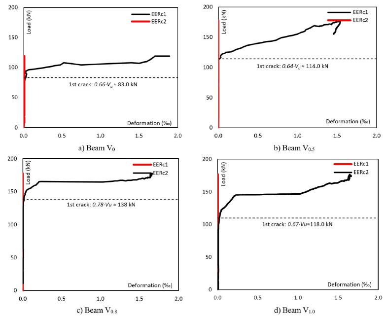
Figure 11 shows results of the relationship load-strain (V-εs). However, only one of the two extensometers, EERc1 (installed on the concrete close to the support) and EERc2 (installed on the concrete close to the load) registered adequately (Figure 2) the strains of the concrete, or rather, EERc1 for beams V0, V0.5 and V1.0, and EERc2 for beam V0.8. Relations V-εs evidenced a pattern of bilinear behavior. The theory foregrounding this type of behavior is related to the formation and evolution of shear inclined cracks. The load at the start of the second linear stretch corresponded approximately to the instant that shear inclined crack intercepted the instrumented concrete (Figure 11). There was a minimum or no contribution of concrete in the beams´ resistance to shearing prior to interception. The scenario explains the rigid stretch, first linear stretch, of beams V0, V0.5, V0.8 and V1.0. Table 7 shows coordinates that define last load (Vu - εsu) and the coordinate that indicates the start of the second linear stretch (V2L-ε2L). When strain εsu is analyzed, it may be seen that there was no discharge of transversal concrete in any beam, εsu<εsy = 3.05‰. Further, ratio εsu,SFRC/εsu,SC ∈ [0.75-0.85] reveals that strain level of SFRC beams is less than that of control (V0). The above indicates that the steel fiber-based reinforcement mechanism mitigates stress on the concrete and, thus, the possibility of reducing the rate of transversal concrete even at minimum rate, ρw=ρw,min. Ding (2012DING, Y. (2012). Investigations into the relationship between deflection and crack mouth opening displacement of SFRC beam. Elsevier, Construction and Building Materials, V 25, 0950-0618.), Amin and Foster (2016AMIN, A., FOSTER, S. J. (2016). Shear strength of steel fibre reinforced concrete beams with stirrups. Engineering Structures 111, 0141-0296.) and other researchers have reached the same conclusions. In the case of assets due to fibers, the ratio V2L,SFRC/V2L,SC ∈ [1.37-1.66] demonstrates that, at the start of the mobilization of transversal concrete, SFRC beam stirrups have more demands than those of beam V0. However, as loading evolves, the fibers take over the main reinforcement and, when close to failure, we have εsu,SFRC/εsu,SC ∈ [0.75-0.85], validating the mitigation of stress on the SFRC beam stirrups. Ratio εs2L,SFRC/εs2L,SC merely reinforces assessment of ratio V2L,SFRC/V2L,SC.
5.4. Failure of beams
Among other aspects, analysis registers the integrity of beams when the specimens´ failure is imminent. In the case of beam V0, Figure 12a reveals the fragility of the specimen with regard to transversal stress (ρw=ρw,min) and its failure mode, namely, shear by diagonal strain with a single inclined crack. However, the SFRC beams (V0.5, V0.8 and V1.0) revealed similar crack patterns since relationships V-δ demonstrated similarity in the specimens´ behavior (Figures 12b, 12c and 12d). Stress mechanism provided by fibers was crucial to restrain the evolution of the shear critical crack reported in beam V0 and to alter the failure mode of SFRC beams. Fibers´ stress caused multiple cracks in the area analyzed (the transversally less stressed area), confirming the fibers capacity in transferring stress within a cracked plane.
5.5. Estimates of resistance
Table 8 provides a synthesis of shear resistance (VR) at Vcort=2.0∙VR and a summary of the calculation of Vflex and Vcort. It also shows the relationship Vflex/Vcort which represents estimates on the beams failure mode at Vflex/Vcort > 1.0, failure by shear mode, and Vflex/Vcort <1.0 failure by flexure. Responses by ratio Vflex/Vcort identify failure of control beam by shearing and the failure of SFRC beams by flexure. At this stage, it is important to comment the poor results of several characterization assays, or rather, mean resistance to compression for concrete C0.8 and residual tensions fRi (i=1 and 3) retrieved from the flexure tests of notched prisms. So that events may be elucidated, Vflex of SFRC beams was assessed: fcm was employed for calculations derived from control tests, beam specimens and suggestions by Moraes Neto et al. (2013)MORAES NETO, B.N., BARROS, J.A.O., MELO, G.S.S.A. (2013). A model for the prediction of the punching resistance of steel fibre reinforced concrete slabs centrically loaded. Construction and Building Materials 46, 0950-0618. to estimate residual stress (Equations 4 and 5). The above remarks make viable the approximate reproduction of beam behavior. It may be concluded that results of fcm≈40 MPa for concrete C0.8, as the test with the cylinders’ axial compression (Table 1), are not acceptable. In fact, they fail to describe SFRC beam behavior experimentally. Consequently, results of residual stress were lower than expected.
6. CONCLUSIONS
The present research evaluates the effectiveness of steel fibers in the mechanical performance of shear beams in concrete. It is recalled that for the experimental study, 4 beams (150x300x2700 mm3) were tested until breakage occurred, one being a control sample, without fibers, and 3 being of SFRC. The concrete strength class was 30.0 MPa at 28 days of age. For the SFRC beams, Dramix 65/60 BG 3D fibers were used, with the fiber content varying at 0.5%, 0.8% and 1.0%. In addition to the reinforcement provided by the fibers, it is reported that all the beams also presented longitudinal and transversal reinforcement, with ρflex=0.91% and ρw=0.08%. For the moment, it is opportune to comment that the transversal reinforcement corresponded to the minimum specified by the ρw=ρw,min Model Code (2010). Based on the analysis carried out, the research conclusions are discussed below:
-
Axial compressive assay of cylinders revealed that steel fibers minimally affected mean resistance to SFRC compression, with fcm,SFRC/fcm,SC≈1.20 for concrete C1.0, although concrete C0.8 shows a relation fcm,SFRC/fcm,SC=1.57, it must be observed that the technological control for test specimens with 0.8% fiber is questionable. However, the relationship between SFRC strains and control, εfcm,SFRC/εfcm,SC ∈[1.25-1.50] showed that steel fibers significantly modifies εfcm. It is a good condition for the ductility of compressed concrete.
-
The flexure test on notched prism showed that linear response of the relationship tension-displacement (f-δ) was not affected by the addition of fibers. Alterations were significant for concrete in tension fLP, with fLP,SFRC/fLP,SC ∈ [1.20-1.45]. However, residual tensions of SFRC concretes were below the capacities that material would provide.
-
So that poor results on residual tensions could be elucidated, fiber direction (FD) was a determinant factor. It varied by 0.30±0.02, lower than that suggested by the literature, FD≈0.5. Further, several fibers directed in parallel to the breaking plane of the prisms were verified. This fact reinforces and justifies the poor report on residual tensions.
-
Load-displacement relationship (V-δ), obtained from the beam assay, revealed that the beams´ capacity provided ratio Vu,SFRC/Vu,SC≈1.40, regardless of the number of fibers used in the test. Reports also showed that the structural behavior was invariable for SFRC beams.
-
V-δ relationship of beams revealed the positive influence of steel fibers on ductility and tenacity of the beams, in which ratio δu,SFRC/δu,SC increases when Cf, rises, with δu,SFRC/δu,SC ∈ [3.0-4.0]. Significant increases in tenacity (TE) were reported for SFRC beams, TE,SFRC/TE,SC≈9.0±1.0.
-
In the case of fiber-less beams, the flexural reinforcement rate increased the mobilization of transversal stress which failed to be endured by ρw. Result consisted of beam failure by shearing. In the case of SFRC beams, hybrid stress (fibers + stirrup) caused a more ductile failure, flexure.
-
The ratio V2L,CRFA/V2L,CS ∈ [1.25-1.65] indicates that at the beginning of the transverse reinforcement mobilization, the stirrups of SFRC beams are depended upon more than those of the V0 beam. However, as loading continues, the fibers assume the main reinforcement function up to breaking point, since the ratio εsu,SFRC/εsu,SC ∈ [0.75-0.85] in the mobilization of transversal reinforced concrete suggests that the strain level in the stirrups of SFRC beams is less than that of the reference beam. The present finding is an indication that the reinforcing mechanism provided by steel fibers alleviates stresses in the reinforcement (stirrups), which represents the possibility of reducing ρw, even when ρw=ρw,min.
-
Current analysis provided an important aspect on the application of hybrid strain. When steel fibers function as transversal strains, ρflex should not constrain strain within the tensile area of the specimen. This would imply increasing strain in the compressed area where the influence of the fiber is limited, and constrain cracking which is required to mobilize the mechanism of fiber stress. Control of cracks or the maintenance of transference of strain during the formations of cracks should be warranted by fibers. Otherwise, SFRC performance would be minimal.
Acknowledgements
The authors would like to thank CAPES, PPGEC, ITEC and GAEMA for funding during all the phases of current research. Thanks are also due to Belgo Bekaert Amares Ltda for donating steel fibers used in the study.
References
- ABNT NBR NM 67 (1998): Concrete - Determination of consistency by discounting the cone´s trunk.
- ABNT NBR NM 248 (2003a): Pebbles - Determination of granulometric composition.
- ABNT NBR NM 52 (2003b): Small pebbles - Determination of specific mass and apparent specific mass.
- ABNT. NBR ISO 1920-3 (2004): Testing of concrete- Part 3: Making and curing test specimens.
- ABNT NBR NM 45 (2006): Pebbles - Determination of unit mass and volume of empty spaces.
- ABNT NBR NM 53 (2009): Large pebbles - Determination of specific and apparent mass and water absorption.
- ABNT NBR ISO 6892 (2013): Metallic materials - Starin assay. Part 1: Method for assay at room temperature.
- ABNT NBR 7680 (2015): Concrete - Extraction, preparation, assay and analysis of control in concrete structure. Part 1: Resistance to axial compression.
- ACI Committee (2010): Guide for Obtaining Cores and Interpreting Compressive Strength Results.
- ACI Committee (2011). Building code requirements for structural concrete and commentary.
- AMIN, A., FOSTER, S. J. (2016). Shear strength of steel fibre reinforced concrete beams with stirrups. Engineering Structures 111, 0141-0296.
- BARROS, A. R., GOMES, P. C. C., BARBOSA, A. S. R. (2011). Steel fibers reinforced self-compacting concrete - behavior to bending. Ibracon Structure and Materials Journal 4, 1983-4195.
- BARROS, J. A. O., ANTUNES, J. A. B. (2003). Experimental Characterization of the Flexural Behaviour of Steel Fibre Reinforced Concrete According to RILEM TC 162-TDF Recommendations. RILEM TC 162 TDF Workshop.
- CONFORTI, A., MINELLI, F., PLIZZARI, G.A. (2013). Wide-shallow beams with and without steel fibres: A peculiar behavior in shear and flexure. Composites: Part B 51, 1359-8368.
- DING, Y. (2012). Investigations into the relationship between deflection and crack mouth opening displacement of SFRC beam. Elsevier, Construction and Building Materials, V 25, 0950-0618.
- DUPONT, D., VANDEWALLE, L. (2005). Distribution of steel fibres in rectangular sections. Cement and Concrete Composites 27, 0958-9465.
- FRITIH, Y., VIDAL, T., TURATSINZE, A., PONS, G. (2013). Flexural and Shear Behavior of Steel Fiber Reinforced SCC Beams. KSCE Journal of Civil Engineering, 1976-3808.
- JAIN, K., SINGH, B. (2016). Deformed steel fibres as minimum shear reinforcement - An investigation. Structures - Elsevier, V 7, 126-137.
- KANG, T. H., KIM, W., MASSONE, L. M., GALLEGUILLOS, T.A. (2012). Shear-Flexure Coupling Behavior of Steel Fiber-Reforced Concrete Beams. ACI Structural Journal 109, 0889-3241.
- KHAN, S., KHAN, R. A., KHAN, A. R., ISLAM, S. (2016). Strength Gain Analysis of Polypropylene Fiber Reinforced Concrete. International Journal of Scientific Research in Science, Engineering and Technology. 2394-4099.
- KRENCHEL, H. (1964). Fibre reinforcement: theoretical and practical investigations of the elasticity and strength of fibre-reinforced materials. Copenhagen, Akademisk Forlag.
- LEE, C., KIM, H. (2010). Orientation factor and number of fibers at failure plane in ring-type steel fiber reinforced concrete. Cement and Concrete Research 40, 0008-8846.
- MACGREGOR, J.G., WIGHT, J.K. (2012). Reinforced concrete - Mechanics and design. 4a ed., Upper Saddle River, Ed. Prentice Hall.
- MINELLI, F., CONFORTI, A., CUENCA, E., PLIZZARI, G. (2014). Are steel fibres able to mitigate or eliminate size effect in shear?. Materials and Structures 47. 1871-6873.
- MOBASHER, B., YAO, Y., SORANAKOM, C. (2015). Analytical solutions for flexural design of hybrid steel fiber reinforced concrete beams. Engineering Structures 100, 0141-0296.
- MODEL CODE (2010). CEB-FIP model code 2010 - Final draft. Lausanne, Switzerland: Thomas Thelford.
- MORAES NETO, B.N., BARROS, J.A.O., MELO, G.S.S.A. (2013). A model for the prediction of the punching resistance of steel fibre reinforced concrete slabs centrically loaded. Construction and Building Materials 46, 0950-0618.
- NARAYANAN, R., DARWISH, I. Y. S. (1987). Use of steel fibers as shear reinforcement. ACI Structural Journal, 0889-3241.
- RILEM TC 162-TDF. (2002). Test and design methods for steel fibre reinforced concrete: Uniaxial tension test for steel fibre reinforced concrete, Recommendation. Materials and Structures, v. 34, p. 3-6.
- SATPUTE, P. C., KULKARNI, V. P., KANDEKAR, S. B. (2016). Mechanical Properties of M25 Grade Concrete by Using Steel and Glass Fibers. International Journal of Engineering Science and Computing, Vol 6, 2321-3361.
- TAHENNI, T., CHEMROUK, M., LECOMPTE, T. (2016). Effect of steel fibers on the shear behavior of high strength concrete beams. Construction and Building Materials 105, 0950-0618.
- YOO, D., BANTHIA, N., YANG, J., YOON, Y. (2016). Size effect in normal- and high-strength amorphous metallic and steel fiber reinforced concrete beams. Construction and Building Materials 121, 0950-0618.
- YOO, D., YANG, J. (2018). Effects of stirrup, steel fiber, and beam size on shear behavior of high-strength concrete beams. Cement and Concrete Composites.
- YOO, D., YUAN, T., YANG, J., YOON, Y. (2017). Feasibility of replacing minimum shear reinforcement with steel fibers for sustainable high-strength concrete beams. Engineering Structures, 147, 207-222.
- YOU, Z., DING, Y., NIEDEREGGER, C. (2010). Replacing Stirrups of Self-Compacting Concrete Beams with Steel Fibers. Transactions of Tianjin University. Vol 16, 1006-4982.
Publication Dates
-
Publication in this collection
2018
History
-
Received
29 Nov 2017 -
Reviewed
23 Mar 2018 -
Accepted
17 Apr 2018


 NOTE: Rates within brackets represent beam tenacity, in Joules.