Abstract
In this paper a mathematical model was found, and numerical results obtained for the pendulum behavior when coupled to a DC generator. A simple pendulum is vertically excited on its support and consequently exhibiting oscillations and rotations. The motion of the pendulum spins the axis of a DC generator and inducing a current. The dynamic model involving the generator and the pendulum dynamics is developed and analyzed in this article. Bifurcation diagrams demonstrate doubling-period and saddle-node bifurcations with the chaos. The presence of chaos is verified by the Lyapunov exponents applied on the time series of the pendulum speed and position. Nonideal interactions of a DC motor with a pendulum by a crank-shaft-slider mechanism is analyzed and compared with an ideal excitation of the pendulum.
Keywords
Energy harvesting; DC generator; pendulum; chaos
1 INTRODUCTION
The main aim in this paper is the analysis of types of motion of the parametric pendulum coupled to a DC generator. The mathematical modeling was firstly obtained and described in Avanço et al. (2017Avanço, R.H., Tusset, A.M., Suetake, M., Navarro, H., Balthazar, J.M, Nabarrete, A. (2017) The pendulum dynamic analysis with DC motors and generators for sea waves energy harvest, DSTA2017 Vibration, Control and Stability of Dynamical Systems, ISBN 839353125X, 9788393531257, Lodz, Poland, 2017.) where the results demonstrated that the pendulum may exhibit both oscillations and rotations. In the present paper a deeper analysis will be performed.
The first analyses of the parametric excited chaotic pendulum are in Leven and Koch (1981Leven, R.W., Koch, B.P. Chaotic Behavior of a Parametrically-Excited Pendulum, Physics Letters A, vol.86, 1981.) where the chaos was verified with Lyapunov exponents and the appearance of a strange attractor in the Poincaré section. A clear analysis of rotating orbits of the classic parametric pendulum is presented in Xu et al. (2005Xu, X.; Wiercogroch, M.; Cartmell, M.P. Rotating Orbits of a Parametrically-excited pendulum, Chaos Solitons and Fractals, v.23, pp.1537-1548, 2005.), at that moment the study of the parametric pendulum dynamics was already justified with the possibility of energy harvesting from sea waves. Also, in Xu et al. (2005), perturbation methods are applied on order to find the motion for small angles of oscillation. Basins of attractions demonstrated that the same conditions of damping, frequency and amplitude of oscillations may lead the pendulum to either oscillations or rotations, depending on initial conditions of position and velocity of the pendulum.
The classic parametric pendulum exhibits different types of motion depending on initial position and velocity, damping, length of pendulum, natural frequency, amplitude and frequency of excitation and the mass in the tip of the pendulum.
The parametric pendulum excited by a crank-shaft-slider mechanism was firstly studied taking into account the geometric complexity of the mechanism in Avanço et al. (2014Avanço, R.H., Navarro, H.A., Brasil, R.M.L.R.F., Balthazar, J.M. (2014) Nonlinear Dynamics of a Pendulum excited by a crank-shaft-slider mechanism. ASME International Mechanical Engineering Congress and Exposition, Volume 4B: Dynamics, Vibration, and Control (4B): V04BT04A025. doi:10.1115/IMECE2014-36643.
https://doi.org/10.1115/IMECE2014-36643...
). Commonly, the slider was considered to move according to a harmonic oscillator. This approach is reasonable only when the crank is sufficiently smaller than the shaft linked to the slider. In the comparison of the classical parametric pendulum and the pendulum vibrated by the crank-shaft-slider mechanism using parameter plots with frequency and amplitude of excitation, it was seen that the chaos occurs in wider regions of crank-slider than in the harmonic classical parametric pendulum.
The classical parametric pendulum is defined by a rigid simple pendulum with a bob in the extreme vibrated vertically on the support by a harmonic motion. The pendulum vibrated vertically by a crank-shaft-slider is also considered a parametric pendulum, since the joint of pendulum is moved in the vertical direction, not in the horizontal.
A horizontal excitation of the pendulum by limited power supply was performed in Krasnopolskaya and Shvets (1993Krasnopolskaya, T.S. and Shvets, A.Y. Chaos in vibrating systems with a limited power-supply, Chaos, Vol.3, n.3, American Institute of Physics, 1993.) and in Belato et al. (2001Belato, D.; Weber, H.I.; Balthazar, J.M.; Mook, D.T. Chaotic Vibrations of a nonideal eletro-mechanical system, International Journal of Solids and Structures, Vol.38, pp. 1699-1706, 2001.). The conclusion was that the consideration of the limited power supply was important to identify the chaos. An approach to an ideal model would hide the chaotic motion of the pendulum.
A pendulum horizontally driven by a DC motor was studied in Kazmierczak et al. (2015Kazmierczak, M., Kudra, G., Awrejcewicz, J., Wasilewski, G. Mathematical modelling, numerical simulations and experimental verification of bifurcation dynamics of a pendulum driven by a dc motor. Eur. J. Phys. 36 (2015) 055028 (13pp) doi:10.1088/0143-0807/36/5/055028, 2015
https://doi.org/10.1088/0143-0807/36/5/0...
). A mathematical modeling, numerical simulation and experimental verification of bifurcation dynamics of the pendulum were performed. The theoretical considerations include constant angular velocity of the crank and the parameters of the model estimated using experimental data obtained from five different solutions for five different voltages. An approach to a single degree was carried out with different models of resistance in the pendulum joint. The results considered a combination of dry friction and viscous damping which yielding to better solutions.
A small voltage was set in the experiments studied in Wasilewski et al. (2015Wasilewski, G., Kudra, G., Awrejcewicz, J., Kazmierczak, M., Tyborowski, M., Kazmierczak, M. Experimental and numerical investigations of a pendulum driven by a low-powered DC motor. Dynamical System-Mathematical and Numerical Approaches, TU of Lodz, NUM305-15, 2015. ) and Wasilewski et al. (2016) where the pendulum was horizontally moved by a low-powered DC motor. The power supplied by the motor was maintained small to allow the return influence of the pendulum dynamics on the motor velocity. Numerical solutions and experimental data demonstrated a good agreement for stable attractors. In the chaotic zone, the numerical and experimental results diverge, as expected, due to the sensibility of initial conditions. The chaotic behavior is verified by the strange attractor in the Poincaré section. In Wasilewski et al. (2016), a new model for the resistance in the joint was developed. The sign functions in the dry model was identified by experimental data instead of a smooth approximation of the sign function. This model leads to advantages in the sense of accuracy and speed of simulation. Another good aspect is the avoidance of stiffness in the differential equation.
Over one hundred fifty variations concepts of Wave Energy Converter (WEC) exist and new ones continue to appear (Falcão, 2010Falcão, A.F. O., Wave energy utilization: a review of the Technologies, Renew. Sustain. Energy Rev., 14, 2010, 899-918.). Some of them are in the commercialization stage and, but despite of this, the costs keep considerable high compared to coal and wind energy. A new wave energy converter based on the parametrically excited pendulum was presented in Yurchenko and Alevras (2018Yurchenko, D. and Alevras, P. Parametric pendulum based wave energy converter. Mechanical Systems and Signal Processing 99 504-515, 2018. Doi: http://dx.doi.org/10.1016/j.ymssp.2017.06.026
http://dx.doi.org/10.1016/j.ymssp.2017.0...
). This mechanism reduces the influence of the gravity force and achieves a dominant rotational motion without any active control. The design which reduces the gravity influence consists of a pendulum suspended on an inclined plane. Experimental results confirmed the numerical results and power harvesting potential is also analyzed.
The parametric excited pendulum was studied for oscillatory motion for energy harvesting using a DC generator in Marszal et al. (2017Marszal, M., Witkowski, B., Jankowski, K., Perlikowski, P., Kapitaniak, T. Energy Harvesting from Pendulum Oscillations. International Journal of Non-Linear Mechanics, 94, 2017. http://dx.doi.org/10.1016/j.ijnonlinmec.2017.03.022
http://dx.doi.org/10.1016/j.ijnonlinmec....
). The numerical studies analyzed the oscillatory motion in 2:1 resonance verified with experimental results. In comparison with the present article, this numerical analysis brings oscillatory and rotational motion, but without the experimental results. The results from Marszal et al. (2017) allowed to conclude that the energy harvesting is more efficient for shorter reduced length of pendulum, which provides low natural periods and larger angular velocity, what is important for increasing the angular velocity of the pendulum acting on the generator.
Concerning rotational solution of the classic parametric pendulum, it was executed successfully an experiment in Lenci et al. (2011) and Lenci (2014). The intention was to verify experimentally the rotational solutions for different amplitudes and frequency of excitation with waves in a tank showing the feasibility of energy harvesting through the pendulum.
A system with two pendulums has been analyzed with a view of energy harvesting in Wiercigroch et al. (2009Wiercigroch, M., Najdecka, A., Vazirii, V., Nonlinear dynamics of pendulums system for energy harvesting, in: Vibration Problems ICOVP 2009, Springer, 2009, pp. 35-42.). Some experiments have been executed with a shaker vibrating the two pendulums under the same support. The control applied successfully could maintain both pendulums under rotational motion synchronized.
In Horton et al. (2008Horton, B.W., Wiercigroch, M., Xu, X. Transient tumbling chaos and damping identification for parametric pendulum. Philos. Tran. R. Soc. A 366, 767-784 (2008)) a solution for the friction was performed based on the decrement parameter found with the experimental results of the damped pendulum. According to Paula et al. (2006Paula, A. S., Savi, M. A. & Pereira-Pinto, F. H. I. 2006 Chaos and transient chaos in na experimental nonlinear pendulum. J. Sound Vib.294, 585-595. (doi:10.1016/j.jsv.2005.11.015)
https://doi.org/10.1016/j.jsv.2005.11.01...
), viscous damping is more relevant when larger angles are present in oscillations. Horton et al. (2008) considered for small oscillations dry friction becomes prevalent and neglect this could lead to out of phase motions when comparing experimental and numerical results. These assumptions allowed to reduce errors and better predict amplitude oscillations when the pendulum approaches to the resting position.
Xu et al. (2007Xu, X., Pavlovskaia, E., Wiercigroch, M., Romeo, F., Lenci, S.: Dynamic interactions between parametric pendulum and electro-dynamical shaker. Z. Angew. Math. Mech. 87, 172-186 (2007).) studied the interactions between the parametric pendulum and a shaker. Quasiperiodic rotations were found experimentally where this type of motion could not be predicted by ideal excitation. Afterwards, the nonideal consideration of a two and a half degree of freedom allowed to properly find these kinds of motion.
A dynamical integrity analysis was performed in Lenci and Rega (2011) considering the basins of attraction. In experimental results, it was verified that rotating solutions could be performed only when the attractor is enough robust and basins large enough.
Alevras et al. (2015) analyzed the dynamics of a tri-pendulum. The reason presented is that the simple pendulum provides rotating solutions only for low frequencies of ocean waves. Some advantages are multiplicity of configurations, it means one may change its size without changing the tri-pendulum behavior.
Stochastic dynamics of a rotating pendulum is investigated in Andreeva et al. (2015Andreeva, T., Alevras, P., Naess, A., Yurchenko, D., Dynamics of a parametric rotating pendulum under a realistic wave profile, Int. J. Dynam. Control (2015). https://doi.org/10.1007/s40435-015-0168-z
https://doi.org/10.1007/s40435-015-0168-...
). The assumptions were based on a realistic wave profile acting on the parametric pendulum. It was verified that the wave asymmetry influences significantly the rotational potential of the pendulum, causing sometimes oscillatory responses.
Two pendulums were mounted on a mutual elastic single degree-of-freedom in Alevras et al. (2014). The response was analyzed with the base externally excited by a random phase sinusoidal force. The goal was to preserve the rotary response. In results it was observed rotations with synchronizations.
2.2 Mathematical modeling
The first mechanism in Figure 1 is the classical parametric pendulum. A harmonic motion is present on the pivot causing different types of motion in the pendulum. It may be observed rotational motion in the pendulum, simple oscillations or a mix between them, what is called oscillation-rotation. The dynamics in steady state may also be a fixed point, the pendulum at rest, and the tumbling chaos. The pendulum rotates and inverts the velocity in a chaotic way.
The length of the pendulum is given by the term , the mass of the bob by . The term stands for the harmonic displacement which causes the resonance in the pendulum. The position of the bob in the extreme of the pendulum is given in cartesian coordinates x and y.
The derivatives in time of x and y are written in Equation (2) where the dots mean the derivatives with respect to the physical time t:
The reference for the gravitational potential energy is the point of suspension of the pendulum, so the Kinetic and Potential Energies are written in Equation (3):
The Lagrangian function based on the Kinect and Potential energies is written as:
Considering the dissipative forces due to the viscous friction in the joint, the generalized dissipative force related to the coordinate has a dimension of torque:
The frequency of the harmonic oscillation of is given by the term Ù and the amplitude by the term :
The differential equation for the mechanism in Figure 1 is given in Equation (7):
In order to perform a dimensionless analysis, it is introduced dimensionless parameters, similarly to that carried out in Xu et al. (2005Xu, X.; Wiercogroch, M.; Cartmell, M.P. Rotating Orbits of a Parametrically-excited pendulum, Chaos Solitons and Fractals, v.23, pp.1537-1548, 2005.).
The prime represents the derivatives related to the dimensionless time and the dots the derivatives related to the physical time . After substituting the dimensionless parameters, the final dimensionless equation is obtained as in Xu et al. (2005Xu, X.; Wiercogroch, M.; Cartmell, M.P. Rotating Orbits of a Parametrically-excited pendulum, Chaos Solitons and Fractals, v.23, pp.1537-1548, 2005.):
The presence of the DC generator in the system demands the usage of one more equation. The generator is coupled to the pendulum and, consequently, they rotate at the same speed or . The electric equation of the generator is given by:
The letter stands for the inductance in the generator, is internal resistance of the inductor and any other resistance present. The term i is the electric current, is the constant of speed and the constant of torque.
When the DC generator is coupled to the mechanism the dynamical equation of the pendulum includes the opposing force of the generator using the constant of torque and the electric current :
In the interest of obtain the nondimensional version of Equations (10) and (11), some more dimensionless parameters were proposed:
The term Q represents any arbitrary value for electric charge allowing the obtainment of dimensionless term for the generator in Equation (13). The term is the natural frequency of the pendulum determined by the length of the pendulum and gravitational acceleration.
Including the DC generator effect in the pendulum, the equation of motion such as Equation (9) turns into:
The value of â, æ and ë , along this paper will be equal to 1. The value of ã will always be 0.1 and other values may change according to what is being specified. The term I represents a dimensionless current which interferes in the pendulum dynamics. Despite this, electric current and electric energy will not be studied in the present analyses.
The modeling in Figure 2 considers a DC motor coupled to a crank-shaft-slider mechanism moving the point of suspension of the pendulum. The main difficulty in this mechanism is to take into account the complexity of the geometry of the crank-slider. When you consider the crank rotating with a constant speedy, you are considering the ideal mechanism explored in Avanço et al. (2016Avanço, R.H., Navarro, H.A., Brasil, R.M.L.R.F., Balthazar, J.M., Bueno, A.M., Tusset, A.M. (2016) Statements on nonlinear dynamics behavior of a pendulum, excited by a crank-shaft-slider mechanism, Meccanica 51, 1301-1320.), where the influence of different crank length is studied. In this article we are going to study this mechanism but considering the nonideal excitation. It means the pendulum may affect the dynamics of the crank powered by the DC motor.
Following the steps to determine the Lagrangian function, the Kinect and potential energies in this case include de inertia of the disc, in addition to the pendulum. Looking at the Figure 2, it is written the position of the bob in the extreme through the angles.
Kinect and potential energies are written in terms of the coordinates and . In this model the crank speedy is not constant. The disc is powered by the DC motor and the disc rotation moves the suspension of the pendulum through the crank-slider.
Using trigonometry, the value of may be determined in terms of è.
The Kinect energy of the system includes the moment of the inertia of the disc plus the rotor of the DC motor. The sum of them is given by where their speedy are the same given by .
The derivatives of the cartesian coordinates in terms of and are given in Equation (18), where it uses an auxiliary function described in Equation (19). This function is a consequence of the geometry of the crank-slider mechanism.
The Lagrangian function obtained by the Kinect and potential energies in terms of and is given by:
The dissipative generalized forces are:
The symbol represents the viscous friction coefficient in the joint where the pendulum is suspended. The is the torque provided by the DC motor to the disc. The term represents the viscous friction in the center of the disc. This friction due to is neglected.
Deriving the Lagrangian function through the Lagrange equations, we found the two differential Equations (21) and (22). The obtainment of Equation (22) began by the Equation (10), if one can consider the electric constant of the motor L/R is smaller than the , the electric equation of the motor allow us to determine the torque supplied through the voltage set and calculate by the Equation (24).
Using the dimensionless terms, based mainly in the dimensionless time, the Equations (22), (23) and (24) were rewritten as in Equations (25), (26) and (27). The auxiliary function F derived with respect to the dimensionless time is presented in Equation (28).
3 RESULTS
The presence of the DC generator modifies the dynamics of the pendulum. However, the kinds of motion are the same. A shift took place when we compare the types of motion. The dynamic behavior depends on the parameter of the generator. A generator designed to produces a bigger power will be a device that has a greater torque opposing to the pendulum motion.
3.1 Bifurcation diagrams and results for the pendulum coupled to the DC generator
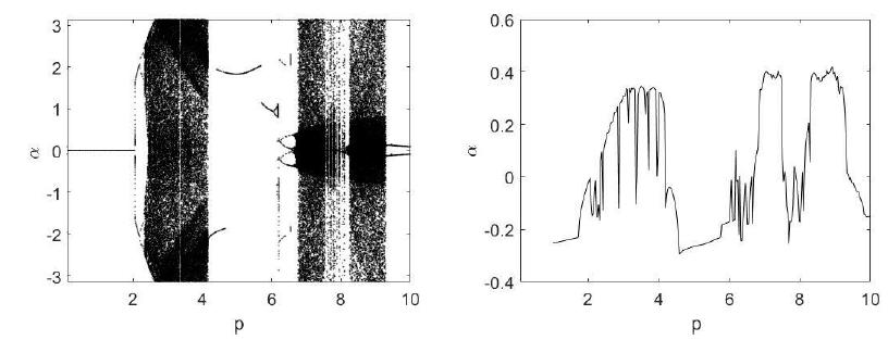
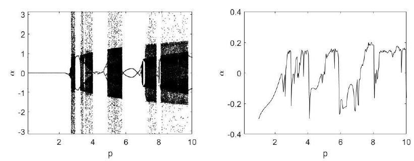
The bifurcation diagrams were constructed based on the resonance zones. They are the same present in Xu et al. (2005Xu, X.; Wiercogroch, M.; Cartmell, M.P. Rotating Orbits of a Parametrically-excited pendulum, Chaos Solitons and Fractals, v.23, pp.1537-1548, 2005.). Those resonance regions in the parametric pendulum were equal to 1.8 in Figure 3, 0.9 in Figure 4 and 0.575 in Figure 5. The values of the Lyapunov exponent indicated chaos when the values are positive. Considering the graphics of Lyapunov exponents, one can affirm that they point the chaos in the same regions of that observed in the bifurcation diagrams. The time elapsed for the obtainment of bifurcation diagrams was equal to 300. It was plotted only the Poincaré sections between 150 and 300 of the time history.
In the Figure 6(b) the Poincaré section shows a strange attractor with fractal appearance, which indicates the presence of chaos. The pendulum dynamics was, in this case, a tumbling chaos. Hence, the plot of the phase portrait in Figure 6(a) is performed after undo the laps so that the pendulum is in an interval of - to .
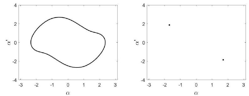
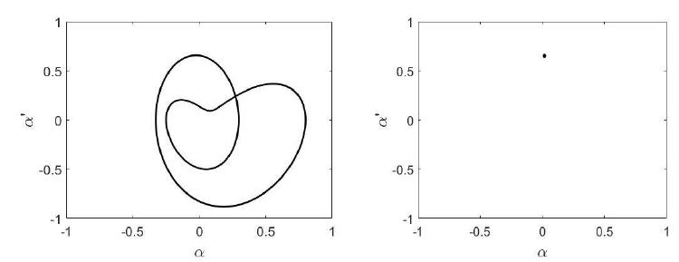
The two-period oscillation in Figure 7 demonstrated that cause of rising of chaos as a doubling period cascade for the bifurcation diagram associated with equal to 1.8. Whilst, the one-period attractor in Figure 8 occurs after a saddle-node bifurcation.
For the frequency of excitation when is equal to 0.575, the bifurcation diagram in Xu et al.(2005Xu, X.; Wiercogroch, M.; Cartmell, M.P. Rotating Orbits of a Parametrically-excited pendulum, Chaos Solitons and Fractals, v.23, pp.1537-1548, 2005.) exhibited the chaos due to a doubling-period cascade. In the present analysis, when the generator is present, for equals to 0.575 the chaos appeared after a saddle-node bifurcation, what one can see in the one-period attractor in the Figure 9.
3.2 Dynamical results for the pendulum vibrated by the DC motor
The parameter of control is the voltage set on the motor. The values used in this nonideal mechanism were: a, b=0.3m, g=9.81m/s2, c=0.32 Ns/m, =0.25m, m=0.5 kg, , , , =0,161 Henry, R=0,365 Ω.
In the Figure 10, it is possible to see a synchronization between the pendulum and the motor. The pendulum speedy is in the Figure 10(b) and the motor speedy in the Figure 10(c). In the same interval of time, the pendulum completed two cycles of oscillation, while the motor executed four cycles of rotation.
Trying to reproduce the same conditions in the ideal model we found a completely different result. The mean value of the motor was worked out and used for an ideal excitation with constant crank speedy . The respective dimensionless parameters are, , =4,918 and ã = 0,1022. The result was a two-period rotation for the ideal situation, while the nonideal model resulted in oscillations of the pendulum. The rotating behavior for the ideal excitation is verified by the time history present in Figure 11(a) and the two-period feature by the Poincaré section in Figure 11(b).
Results for V=4.5 Volts (a) Time history of the pendulum position (b) Pendulum speedy (c) Motor speedy
Results for ideal pendulum , ù=4.918 ; å=0.4, ã=0.1022 (a) Time history of the pendulum position (b) Poincaré section
4 CONCLUSIONS
The results presented in Xu et al. (2005Xu, X.; Wiercogroch, M.; Cartmell, M.P. Rotating Orbits of a Parametrically-excited pendulum, Chaos Solitons and Fractals, v.23, pp.1537-1548, 2005.) demonstrated rising of chaos due to cascate of doubling period bifurcation in diagrams of equal to 1.8 and 0,575. The saddle-node bifurcation caused the chaos in the bifurcation diagram for equal to 0.9. In the results of the present paper, after the inclusion of the DC generator the types of bifurcation were saddle-node for equal to 0.575 and 0.9. With the DC generator, the doubling-period cascade occurred for equals to 1.8. These results demonstrate that for these mechanism, the types of bifurcation may not be associated only with the excitation frequency. The presence of the generator causes changes in these types of bifurcations and causes a shift of where the chaotic regions take place in different ranges in the bifurcation diagrams.
About the analysis of the nonideal excitation of the pendulum by the DC motor, it is possible to state that in this situation of pendulum excitation, the results may be very different if you consider or not the conditions of limited power supply. The result of ideal considerations led to rotational motions, while the nonideal model pointed an oscillation of the pendulum. As affirmed in Kononenko (1969Kononenko, V.O. Vibrating Systems with a Limited Power-Supply, Ed. Ilife, London. (1969)), the nonideal or the limited power supply considerations are important when the energy supplied is next to the energy consumed. The analysis in Kazmierczak et al. (2015Kazmierczak, M., Kudra, G., Awrejcewicz, J., Wasilewski, G. Mathematical modelling, numerical simulations and experimental verification of bifurcation dynamics of a pendulum driven by a dc motor. Eur. J. Phys. 36 (2015) 055028 (13pp) doi:10.1088/0143-0807/36/5/055028, 2015
https://doi.org/10.1088/0143-0807/36/5/0...
) used a single degree to successfully predict a nonideal model for the pendulum horizontally excited, whilst the present analysis maintained a two-degree model to verify the synchronizations in different types of motion. In Wasilewski et al. (2016Wasilewski G., Kudra G., Awrejcewicz J., Kazmierczak M., Tyborowski M., Kazmierczak, M. A Pendulum Driven by a Crank-Shaft-Slider Mechanism and a DC Motor-Mathematical Modeling, Parameter Identification, and Experimental Validation of Bifurcational Dynamics. Dynamical Systems: Theoretical and Experimental Analysis, Springer Proceedings in Mathematics & Statistics 182, 2016, DOI 10.1007/978-3-319-42408-8_31
https://doi.org/10.1007/978-3-319-42408-...
), a new model for the resistance was developed based on a mixture of dry friction and viscous damping, what allowed a good approach to experimental results. Comparing Marszal et al. (2017Marszal, M., Witkowski, B., Jankowski, K., Perlikowski, P., Kapitaniak, T. Energy Harvesting from Pendulum Oscillations. International Journal of Non-Linear Mechanics, 94, 2017. http://dx.doi.org/10.1016/j.ijnonlinmec.2017.03.022
http://dx.doi.org/10.1016/j.ijnonlinmec....
) with the present analysis, the previous used a freewheel to obtain the rotation in the DC generator through pure oscillation in the pendulum where a better efficiency was found for smaller reduced lengths in the pendulum. This analysis verified the types of motion where the pendulum exhibits different types of motion, where oscillations, rotations and tumbling chaos in the pendulum are directly transmitted to the DC generator yielding to the conclusion that energy harvesting may be performed in different types of motion since the pendulum does not stop in the vertical position. For this reason, maintain higher angular velocities are recommended.
References
- Alevras, P., Yurchenko, D., Naess, A., Stochastic synchronization of rotating parametric pendulums, Meccanica 49 (2014) 1945-1954.
- Alevras, P.,Brown, I., Yurchenko, D. Experimental investigation of a rotating parametric pendulum, Nonlin. Dyn. 81 (2015) 201-213.
- Andreeva, T., Alevras, P., Naess, A., Yurchenko, D., Dynamics of a parametric rotating pendulum under a realistic wave profile, Int. J. Dynam. Control (2015). https://doi.org/10.1007/s40435-015-0168-z
» https://doi.org/10.1007/s40435-015-0168-z - Avanço, R.H., Navarro, H.A., Brasil, R.M.L.R.F., Balthazar, J.M. (2014) Nonlinear Dynamics of a Pendulum excited by a crank-shaft-slider mechanism. ASME International Mechanical Engineering Congress and Exposition, Volume 4B: Dynamics, Vibration, and Control (4B): V04BT04A025. doi:10.1115/IMECE2014-36643.
» https://doi.org/10.1115/IMECE2014-36643 - Avanço, R.H., Navarro, H.A., Brasil, R.M.L.R.F., Balthazar, J.M., Bueno, A.M., Tusset, A.M. (2016) Statements on nonlinear dynamics behavior of a pendulum, excited by a crank-shaft-slider mechanism, Meccanica 51, 1301-1320.
- Avanço, R.H., Tusset, A.M., Suetake, M., Navarro, H., Balthazar, J.M, Nabarrete, A. (2017) The pendulum dynamic analysis with DC motors and generators for sea waves energy harvest, DSTA2017 Vibration, Control and Stability of Dynamical Systems, ISBN 839353125X, 9788393531257, Lodz, Poland, 2017.
- Belato, D.; Weber, H.I.; Balthazar, J.M.; Mook, D.T. Chaotic Vibrations of a nonideal eletro-mechanical system, International Journal of Solids and Structures, Vol.38, pp. 1699-1706, 2001.
- Falcão, A.F. O., Wave energy utilization: a review of the Technologies, Renew. Sustain. Energy Rev., 14, 2010, 899-918.
- Horton, B.W., Wiercigroch, M., Xu, X. Transient tumbling chaos and damping identification for parametric pendulum. Philos. Tran. R. Soc. A 366, 767-784 (2008)
- Kazmierczak, M., Kudra, G., Awrejcewicz, J., Wasilewski, G. Mathematical modelling, numerical simulations and experimental verification of bifurcation dynamics of a pendulum driven by a dc motor. Eur. J. Phys. 36 (2015) 055028 (13pp) doi:10.1088/0143-0807/36/5/055028, 2015
» https://doi.org/10.1088/0143-0807/36/5/055028 - Kononenko, V.O. Vibrating Systems with a Limited Power-Supply, Ed. Ilife, London. (1969)
- Krasnopolskaya, T.S. and Shvets, A.Y. Chaos in vibrating systems with a limited power-supply, Chaos, Vol.3, n.3, American Institute of Physics, 1993.
- Lenci, S., Brocchini, M., Lorenzoni, C. Experimental rotations of a Pendulum on Water Waves. J. Comput. Nonlinear Dynam 7(1), 011007 (Aug 15, 2011) DOI: 10.1115/1.4004547
» https://doi.org/10.1115/1.4004547 - Lenci, S., Rega, G. Experimental versus theoretical robustness of rotating solutions in a parametrically excited pendulum: a dynamical integrity perspective, Physica D: Nonlin. Phenom. 240 (2011) 814-824.
- Leven, R.W., Koch, B.P. Chaotic Behavior of a Parametrically-Excited Pendulum, Physics Letters A, vol.86, 1981.
- Marszal, M., Witkowski, B., Jankowski, K., Perlikowski, P., Kapitaniak, T. Energy Harvesting from Pendulum Oscillations. International Journal of Non-Linear Mechanics, 94, 2017. http://dx.doi.org/10.1016/j.ijnonlinmec.2017.03.022
» http://dx.doi.org/10.1016/j.ijnonlinmec.2017.03.022 - Paula, A. S., Savi, M. A. & Pereira-Pinto, F. H. I. 2006 Chaos and transient chaos in na experimental nonlinear pendulum. J. Sound Vib.294, 585-595. (doi:10.1016/j.jsv.2005.11.015)
» https://doi.org/10.1016/j.jsv.2005.11.015 - S. Lenci, On the production of energy from sea waves by a rotating pendulum: a preliminary experimental study, J. Appl. Nonlin. Dyn. 3 (2014) 187-201.
- Wasilewski G., Kudra G., Awrejcewicz J., Kazmierczak M., Tyborowski M., Kazmierczak, M. A Pendulum Driven by a Crank-Shaft-Slider Mechanism and a DC Motor-Mathematical Modeling, Parameter Identification, and Experimental Validation of Bifurcational Dynamics. Dynamical Systems: Theoretical and Experimental Analysis, Springer Proceedings in Mathematics & Statistics 182, 2016, DOI 10.1007/978-3-319-42408-8_31
» https://doi.org/10.1007/978-3-319-42408-8_31 - Wasilewski, G., Kudra, G., Awrejcewicz, J., Kazmierczak, M., Tyborowski, M., Kazmierczak, M. Experimental and numerical investigations of a pendulum driven by a low-powered DC motor. Dynamical System-Mathematical and Numerical Approaches, TU of Lodz, NUM305-15, 2015.
- Wiercigroch, M., Najdecka, A., Vazirii, V., Nonlinear dynamics of pendulums system for energy harvesting, in: Vibration Problems ICOVP 2009, Springer, 2009, pp. 35-42.
- Xu, X., Pavlovskaia, E., Wiercigroch, M., Romeo, F., Lenci, S.: Dynamic interactions between parametric pendulum and electro-dynamical shaker. Z. Angew. Math. Mech. 87, 172-186 (2007).
- Xu, X.; Wiercogroch, M.; Cartmell, M.P. Rotating Orbits of a Parametrically-excited pendulum, Chaos Solitons and Fractals, v.23, pp.1537-1548, 2005.
- Yurchenko, D. and Alevras, P. Parametric pendulum based wave energy converter. Mechanical Systems and Signal Processing 99 504-515, 2018. Doi: http://dx.doi.org/10.1016/j.ymssp.2017.06.026
» http://dx.doi.org/10.1016/j.ymssp.2017.06.026
-
Available online: November 22, 2018
Publication Dates
-
Publication in this collection
2019
History
-
Received
01 Apr 2018 -
Reviewed
20 Aug 2018 -
Accepted
15 Nov 2018