
Abstract
In this work, carbon fibre reinforced polymer (CFRP) plates have been tested under free impact vibration tests in pristine and damaged configurations. The plates were suspended as cantilevers and vibrated using an impact hammer. Two accelerometers and one microphone were used to obtain the vibration response data signals from the pristine and damaged plates, and the frequency response function (FRF) was plotted. The current technique focused on the detected signal from more than one vibration sensor to ensure the measurement's accuracy. Comparisons between the experimental vibration test and the simulated analysis using finite element analysis (FEA) showed that the results agreed. The damage orientation significantly affected the composites’ dynamic properties. The FRF measures of the damaged CFRP composites showed the lowest eigenvalues in the resonant frequencies. The 0/90 layup laminate composite exhibited greater fluctuations in resonant frequencies across the various mode shapes, which reached a 2.85% difference compared to the quasi-isotropic laminate composites.
Keywords:
Carbon Fibre Reinforced Polymer (CFRP); Damage; Frequency Response Function (FRF); CFRP; Damping; Mode Shape
1 INTRODUCTION
Due to the increasing application of carbon fibre reinforced polymer (CFRP) composites, and to prevent composite structures from failing, many researchers have begun monitoring these structures to predict damaged regions and even to detect crack locations (Wen and Choy 2011Wen, J., Z. Xia and F. Choy (2011). “Damage detection of carbon fiber reinforced polymer composites via electrical resistance measurement.” Composites Part B: Engineering 42(1): 77-86.). However, few methods have been developed for monitoring damage characteristics. Vibration analysis is one of the most common methods for detecting damage in composite structures as it determines the structures’ mode shapes and natural frequencies (Maia, et al. 2003Maia, N. M. S., J. M. M., Almas, E. A. M., Sampaio, R. P. C. (2003). “Damage detection in structures: From mode shape to frequency response function methods.” Mechanical Systems and Signal Processing 17(3): 489-498., Manoach, Samborski, et al. 2012Manoach, E., S. Samborski, A. Mitura and J. Warminski (2012). “Vibration based damage detection in composite beams under temperature variations using Poincaré maps.” International Journal of Mechanical Sciences 62(1): 120-132., Manoach, Warminski, et al. 2016, Hammad and Moustafa 2020Hammad, A. H. and E. B. Moustafa (2020). “Study some of the structural, optical, and damping properties of phosphate glasses containing borate.” Journal of Non-Crystalline Solids 544: 120209.). Vibration analysis for cracked composite laminated plate and beam structures was developed by researchers (Ngo-Cong, Mai-Duy, et al. 2011Ngo-Cong, D., N. Mai-Duy, W. Karunasena and T. Tran-Cong (2011). “Free vibration analysis of laminated composite plates based on FSDT using one-dimensional IRBFN method.” Computers & Structures 89(1): 1-13., Iliopoulos, Aggelis, et al. 2015Iliopoulos, S., D. G. Aggelis, L. Pyl, J. Vantomme, P. Van Marcke, E. Coppens and L. Areias (2015). “Detection and evaluation of cracks in the concrete buffer of the Belgian Nuclear Waste container using combined NDT techniques.” Construction and Building Materials 78: 369-378., El-Hafidi, Gning, et al. 2017El-Hafidi, A., P. B. Gning, B. Piezel, M. Belaïd and S. Fontaine (2017). “Determination of dynamic properties of flax fibres reinforced laminate using vibration measurements.” Polymer Testing 57: 219-225.) who have concluded that damage is influenced by a structure’s natural frequency, as the presence of damage decreases the natural frequency. Many investigators have also performed experimental and simulation studies to determine the frequency response function of carbon fibre composites and the dynamic damping behaviour of fabricated composites (Hu, Wang, et al. 2006Hu, H., B.-T. Wang, C.-H. Lee and J.-S. Su (2006). “Damage detection of surface cracks in composite laminates using modal analysis and strain energy method.” Composite Structures 74(4): 399-405., Ding, Xie, et al. 2015Ding, G., C. Xie, J. Zhang, G. Zhang, C. Song and Z. Zhou (2015). “Modal analysis based on finite element method and experimental validation on carbon fibre composite drive shaft considering steel joints.” Materials Research Innovations 19(sup5): S5-748-S745-753., Wang, Qin, et al. 2017, Moustafa 2018). Free vibration analysis and modal tests of carbon fibre composite plates have been carried out by (Della and Shu 2005Della, C. N. and D. Shu (2005). “Free vibration analysis of composite beams with overlapping delaminations.” European Journal of Mechanics - A/Solids 24(3): 491-503., AbuShanab and Moustafa 2018AbuShanab, W. S. and E. B. Moustafa (2018). “Detection of Friction Stir Welding Defects of AA1060 Aluminum Alloy Using Specific Damping Capacity.” Materials (Basel, Switzerland) 11(12): 2437.) to measure the impact of buckling stress on the material’s dynamic properties.
Many authors have characterized these dynamic properties of carbon fibre composites, determining that they depend on the fibre orientation angle, fibre types, measurement methods, and matrix materials (Wright 1972Wright, G. C. (1972). “The dynamic properties of glass and carbon fibre reinforced plastic beams.” Journal of Sound and Vibration 21(2): 205-212., Tsai and Chi 2008Tsai, J.-L. and Y.-K. Chi (2008). “Effect of fiber array on damping behaviors of fiber composites.” Composites Part B: Engineering 39(7): 1196-1204., Pei and Li 2012Pei, X. Y. and J. L. Li (2012). “The Effects of Fiber Orientation on the Vibration Modal Behavior of Carbon Fiber Plain Woven Fabric/Epoxy Resin Composites.” Advanced Materials Research 391-392: 345-348., Muhammet Raci Aydın, Ömer Gündoğdu, et al. 2018Muhammet Raci Aydın, M. R. A., Ö. G. Ömer Gündoğdu, B. K. Barbaros Kaya, G. B. Gürbüz Bayraktar, O. K. A. Okan Kaan Aksuoğlu and O. K. A. Okan Kaan Aksuoğlu (2018). “Effect of Orientation Angles on Vibration Properties at Carbon Fiber Reinforced Polymeric Composites.” E-Journal of New World Sciences Academy 13(3): 180-189.). Unidirectional and flax reinforced carbon fibre composites have been fabricated, and their damping properties have been measured via the logarithmic decrement method; in this case, flax fibres reinforced with different orientation angles were reported as having better damping values (Rueppel, Rion, et al. 2017Rueppel, M., J. Rion, C. Dransfeld, C. Fischer and K. Masania (2017). “Damping of carbon fibre and flax fibre angle-ply composite laminates.” Composites Science and Technology 146: 1-9.). The inverse relationship between damping ratio and natural frequency has also been investigated on a hybrid carbon fibre composite structure; the study revealed that, as the number of carbon fibre layers increases, the natural frequency increases, and the damping ratio decreases (Utomo, Susilo, et al. 2017Utomo, J. T., D. D. Susilo and W. W. Raharja (2017). The influence of the number and position of the carbon fiber lamina on the natural frequency and damping ratio of the carbon-glass hybrid composite.). In addition to fibre layer orientation, CFRP beam length significantly affects the frequency and damping coefficients (Berthelot, Assarar, et al. 2008Berthelot, J.-M., M. Assarar, Y. Sefrani and A. E. Mahi (2008). “Damping analysis of composite materials and structures.” Composite Structures 85(3): 189-204.). Different carbon fibre orientations have been experimentally investigated to obtain the most significant dynamic characteristics, and numerical analysis has been performed, using Ansys finite element analysis (FEA) software, to verify the results (Nagasankar and Velmurugan, 2012P. Nagasankar, S. B. P., R. Velmurugan (2012). “The Influence of the Different Fiber lay-ups on the Damping Characteristics of Polymer Matrix Composite.” Journal of Applied Sciences 12: 1071-1074.).
Many authors have also investigated crack types (macro- or microscopic) and crack propagation (Razvan, Bakis, et al. 1990Razvan, A., C. E. Bakis and K. L. Reifsnider (1990). “SEM investigation of fiber fracture in composite laminates.” Materials Characterization 24(2): 179-190., Kyriazoglou, Le Page, et al. 2004Kyriazoglou, C., B. H. Le Page and F. J. Guild (2004). “Vibration damping for crack detection in composite laminates.” Composites Part A: Applied Science and Manufacturing 35(7): 945-953., Yu, Liu, et al. 2009Yu, J., Y. Z. Liu and R. R. Shi (2009). “Studies on Crack Propagation of Carbon Fiber Reinforced Epoxy Resin Composite.” Advanced Materials Research 79-82: 1029-1033.). Important factors affecting fracture behaviours and mechanisms are the crack’s path and length (Cawley and Adams 1979aCawley, P. and R. D. Adams (1979a). “The location of defects in structures from measurements of natural frequencies.” The Journal of Strain Analysis for Engineering Design 14(2): 49-57., Cawley and Adams 1979b, Ostachowicz and Krawczuk 1990Ostachowicz, W. M. and M. Krawczuk (1990). “Vibration analysis of a cracked beam.” Computers & Structures 36(2): 245-250., Manoach, Samborski, et al. 2012Manoach, E., S. Samborski, A. Mitura and J. Warminski (2012). “Vibration based damage detection in composite beams under temperature variations using Poincaré maps.” International Journal of Mechanical Sciences 62(1): 120-132., Iezzi, Valente, et al. 2020Iezzi, F., C. Valente and F. Brancaleoni (2020). Experimental Validation of Damage Indices Based on Complex Modes for Damage Detection in Vibrating Structures. Proceedings of the 13th International Conference on Damage Assessment of Structures, Singapore, Springer Singapore.). Considering all this, the free vibration impact method is considered the most popular technique for diagnosing different materials' structural health. Hence, modal analysis is the simplest, easiest method for detecting structural damage. The earliest studies on the subject analysed fundamental frequencies; however, due to measurement errors and noise, natural frequencies at such mode shapes were not sensitive to structural damage (Yan and Yam 2002Yan, Y. J. and L. H. Yam (2002). “Online detection of crack damage in composite plates using embedded piezoelectric actuators/sensors and wavelet analysis.” Composite Structures 58(1): 29-38., Pereira, Mikkelsen, et al. 2015Pereira, G. F., L. P. Mikkelsen and M. McGugan (2015). “Crack Detection in Fibre Reinforced Plastic Structures Using Embedded Fibre Bragg Grating Sensors: Theory, Model Development and Experimental Validation.” PloS one 10(10): e0141495-e0141495., Romhány, Czigány, et al. 2017Romhány, G., T. Czigány and J. Karger-Kocsis (2017). “Failure Assessment and Evaluation of Damage Development and Crack Growth in Polymer Composites Via Localization of Acoustic Emission Events: A Review.” Polymer Reviews 57(3): 397-439., Mohan and Poobal 2018Mohan, A. and S. Poobal (2018). “Crack detection using image processing: A critical review and analysis.” Alexandria Engineering Journal 57(2): 787-798.). Therefore, other approaches have been developed to detect and monitor cracks and damage in various structures-e.g., crack growth detecting using ultrasonic and acoustic waves (Wen, Xia, et al. 2011Wen, J., Z. Xia and F. Choy (2011). “Damage detection of carbon fiber reinforced polymer composites via electrical resistance measurement.” Composites Part B: Engineering 42(1): 77-86.). Murčinková, Z. et al., have employed modal analysis, in addition to using vibration analysis to measure damping capacity (Murčinková, Vojtko, et al. 2019). Piezoelectric sensors have also been implemented to detect energy variations using wavelets (Yan and Yam 2002, Chouinard, Shahsavari, et al. 2019Chouinard, L., V. Shahsavari and J. Bastien (2019). “Reliability of Wavelet Analysis of Mode Shapes for the Early Detection of Damage in Beams.” Frontiers in Built Environment 5(91).). Many other computational methods have been carried out to evaluate and assess damage in carbon fibre composites. Their mechanical, dynamic, and thermal properties have been investigated with finite element analysis software. The circular central cutout effect and the fibre orientation angle have also been studied, with the authors concluding that cutouts in carbon fibre composites significantly affect the resonant frequency (Erkliğ, Bulut, et al. 2012Erkliğ, A., M. Bulut and E. Yeter (2012). “Effects of cutouts on natural frequency of laminated composite plates.” Science and Engineering of Composite Materials 0(0): 1-7.). Vibration analysis has been applied to a CFRP tube, attached with a metal flange, to validate FEA simulation's performance and reliability (Sun, Xiao, et al. 2020Sun, Z., J. Xiao, X. Yu, R. Tusiime, H. Gao, W. Min, L. Tao, L. Qi, H. Zhang and M. Yu (2020). “Vibration characteristics of carbon-fiber reinforced composite drive shafts fabricated using filament winding technology.” Composite Structures 241.).
In the current work, multi-sensor vibration averaging was used to detect the effect of crack orientation in carbon fibre composites, and numerical FEA was carried out via the Ansys software to examine different crack scenarios. The previous literature, mainly depending on only one sensor type, has not extensively investigated macroscopic crack width and damage orientation. However, it is worth studying, especially in the presence of numerical simulation analysis software. The impact of damage orientation was experimentally detected in the CFRP composites using multi-sensor vibration averaging measurements in the current work. Experimental free impact vibration tests were conducted on the damaged and pristine CFRP composites. Moreover, calculate material’s dynamic properties; hence, the finite element analysis was applied to locate the most significant damage orientation in the carbon fibre composite structure. The investigation was carried out in three orientations: vertical, horizontal, and diagonal cracks.
2. Materials and Experimental Procedures
2.1 Materials
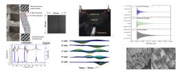
This research employed commercial CFRP composite laminate plates (3mm thick; Shenzen T-Star Composites Co., Ltd). The composite laminates were fabricated from two protective layers of 3K 2×2 twill woven carbon fibre fabric (0.125mm thick) and 22 symmetric layup layers of unidirectional carbon fabric (0.125mm thick). To illustrate the laminate layers' alignment, Fig. 1 shows the CFRP composite's construction before and after removing the polymer resin. The dimensions of the plates were 300×300×3mm.

2.2 Damage Fabrication
The experimental damage was fabricated using a thin disk (1mm thick), which was connected to a rotary tool. Fig. 2 shows the schematics for the fabricated damage in the CFRP sheets. The three damage types were created at the CFRP composite sheet center, and the damage dimensions were 150×1mm.

Schematics of the damage location and crack orientation angle: a) vertical 90° crack, b) diagonal 45° crack, c) horizontal 0° crack.
2.3 Free Vibration Impact Test
The free vibration impact test was carried out on CFRP sheets of 300 mm×280 mm×3mm dimensions. The tested specimens were supported by a special fixture designed to hold the plates as a cantilever beam to measure the impact of damage on the dynamic properties, such as storage modulus and loss factor. Vibration signals were picked up by two Constant Current Line Drive (CCLD) accelerometers (Type 4507-B, Bruel & Kjaer, Naeuram, Denmark). Hence, the accelerometers were supported on the CFRP plate by mounting clips. The acoustic signal was picked up by one microphone (Type 4188, Bruel & Kjaer, Naeuram, Denmark), which was 5mm distant from the CFRP plate. Excitation was initiated using an impact hammer with a force transducer (Type 8206, Bruel & Kjaer, Naeuram, Denmark). Acoustic and vibration signals were acquired and processed using a LAN-XI PULSE analyzer (Type 3050 A-60, Bruel & Kjaer, Naeuram, Denmark).
The fast Fourier transform (FFT) was performed using a 3,200-line resolution and a frequency span of 10kHz. Ten data blocks were set to be averaged using a linear averaging mode. Ten trial impacts were also performed for each test to obtain correct averaged data. After processing, the data was analyzed via MEscope software (Vibrant Technology, Centennial, USA). Fig. 3 shows the schematics for the experimental tests. To calculate the CFRP cantilever beam's dynamic properties, the logarithmic decrement method was used to calculate the damping ratio, as presented in equation (1). From equation (1), equations (2) and (3) were defined to calculate the damping ratio (ζ) and loss factor (η), respectively, for an even number of cycles. Fig. 4 shows the typical time and frequency domain of the experimental free vibration test for the CFRP composite cantilever beam. The dynamic modulus was calculated via equation (4), according to the American Society for Testing and Materials (ASTM) 756 standard.
where:
δ = Logarithmic decrement
n = Number of cycles
xo = Initial amplitude at the peak
xn = Amplitude of the beak after n cycles
ζ = Damping ratio
η = Loss factor
C = Coefficient for mode, n, of clamped-free (uniform) beam; Cn1 = 0.55959, Cn2 = 3.5069, Cn3 = 9.8194
Ed = Young’s modulus of beam material, Pa
fn = The resonance frequency for mode n, Hz
d = Thickness of beam in vibration direction, m
l = length of beam, m
n = Mode number: 1, 2, 3,… etc.
ρ = Density of beam, kg/m3
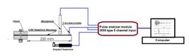
Schematics of experimental setup for the free vibration impact test using a four-channel spectrum analyser
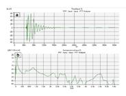
Typical vibration output spectrum; (a) time domain, (b) auto-spectrum response in frequency domain for the cantilever beam specimen
2.4 Characterization of Dynamic Properties
Under specific stresses, CFRP composites follow a viscoelastic behaviour, so the plastic deformation energy of CFRP materials can relate to the storage modulus, dynamic loss modulus, and loss factor properties. The dynamic properties were estimated from the results of the free vibration impact test and the FEA. The main parameters retrieved from the experimental free vibration test were natural frequency and damping ratio. Table 1 shows the dynamic properties of the 180×20×3mm CFRP composite. The dynamic characterization test was performed according to ASTM E1876 - 15 guidelines.
2.5 Characterization of Mechanical Properties and Microstructure
CFRP samples were subjected to a tensile test under ASTM D 3039 guidelines. According to their grip lengths, all samples were bonded by aluminum end tabs to prevent them from slipping out of the tensile test machine’s grip. To record the longitudinal strain during the tensile test, the specimens were monitored using an extensometer (Instron 3442) with a gauge length of 30mm, as shown in Fig. 5. Five specimens were tested at a constant crosshead speed of 1.0mm/min. After the tensile test, the fractured surfaces' microstructures were examined via scanning electron microscopy (SEM, JSM-7600F).
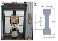
(a) Tensile test of CFRP specimen, (b) schematic drawing for tension test sample with dimensions
3 Results and Discussion
3.1 Tension Test Results
Fig. 6 shows the tensile test results, and Table 2 presents the mechanical properties extracted from the stress-strain plot. Regarding the tensile stress-strain curves of the CFRP composites, the diagram typically behaves almost linearly, followed by nonlinear plastic behaviour. The true Young’s modulus value for the CFRP composites was calculated from the initial linear region slope in the stress-strain diagram. Fig. 7 shows some fractured samples' images, indicating that failure typically occurred in the gauge length, as specified by ASTM D 638. The dynamic and mechanical test results converged for the static and dynamic Young’s modulus values, with the difference between them being 4.03GPa. More than five tests were carried out for each sample, and the standard deviation (Std dev.) was calculated to show the variation in each tested sample.


3.2 SEM Analysis
Fig. 8 shows a typical SEM micrograph for the longitudinal distribution of fibres in a CFRP sample. Carbon fibres have an average diameter of 4.5μm. Energy-dispersive X-ray spectroscopy (EDX) was used to map the composite elements. The EDX analysis revealed only a high percentage of carbon and oxygen, as shown in Fig. 9.
Fig. 10 presents the SEM images for the CFRP samples after the tensile test, and the observed failure is typical of a brittle composite. Fig. 10-b is an enlarged image of the fracture zone; the failure direction was perpendicular to the fibre and load direction.


SEM image of CFRP composite: (a) fracture after tensile test, (b) SEM image of carbon fibre failure surfaces
3.3 Finite Element Model and Boundary Conditions
The finite element model (FEM), via Ansys software, was used to simulate and predict the behavior of cracked structures in different scenarios. Three types of crack orientations were chosen to calculate the impact of the design parameters on the CFRP composite’s dynamic properties. The investigated CFRP composite sheet had fixed dimensions of 300×280×3mm; hence, it was modeled to match the manufacturing process. The Ansys Composite PrepPost (ACP) module is an excellent tool for modeling layered composites. In this case, modal and harmonic response modules were used to simulate dynamic modal analysis and the sampled sheet's mode shapes. The harmonic response module was used in its superposition mode as part of the solution method, and the solution interval was set to 1,000 increment points to increase the resolution of the results in the frequency response function (FRF) plot. The composite material was created via the engineering data manager in the ANSYS library. The current CFRP was fabricated from two protection layers of carbon fibre: woven prepreg-the first on top and the second on the composite's bottom. Also, 22 carbon fibre unidirectional prepreg layers, of 0° and 90°, were laid out sequentially. The CFRP composite had already been modeled as a cantilever sheet.
3.4 Meshing Methods and Sizing Selection
Meshing methods and sizing significantly affect the resonant frequency results at each selected mode shape. Many attempts were made to choose the best resolution that could be obtained and matched with the experimental test. Fig. 11 shows the meshing methods' effect on the resonant frequency and dynamic behaviour during the simulation process. Three types of meshing methods were investigated (according to the FEA options in Ansys) in an attempt to choose the nearest value to the experimental free vibration test: Triangles, MultiZone Triangles, and Quadrilateral Dominant. of these, the MultiZone Triangles mesh type was found to have the lowest variation in resonant frequency, and it achieved minimum resonant frequency values for all studied mode numbers. Mesh size significantly affects the accuracy of the numerical analysis results. In the current investigation, the mesh size was chosen based on a parametric study tool. Hence, the minimum size was 1mm, and the maximum size was 40mm. Therefore, a multi-zone, quad/tri method was used. The meshing elements size was set to 10mm, and there were 2,167 nodes and 4,174 elements. The meshing methods and the effect of crack existence on the CFRP composite are shown in Fig. 12. Boundary conditions were assigned using fixed support from one side of the composite sheet. Modal analysis was conducted for the CFRP sheet; the first six mode shapes and their natural frequencies were computed. 10N force was applied at the end of the sheet to calculate and plot the frequency response function.

3.5 The Dynamic Properties of a Pristine CFRP Composite Plate
A CFRP composite plate was subjected to experimental free vibration and numerical simulation methods to estimate the dynamic properties and detect the resonant frequency at each mode shape. To acquire the necessary signals, three sensors were used. Two accelerometers were fixed at the top corners of the CFRP composite plate, while the microphone was mounted 5mm above the center of the plate. The average frequency response function (FRF) from the three vibration sensors for the undamaged CFRP composite sheet was acquired and is plotted in Fig. 13. The simulation model was implemented on the same properties of the experimental CFRP plate using the Ansys software’s engineering data library; the mechanical properties and the engineering data of the fabricated CFRP sheet were verified in the previous sections. The numerical modal analysis strongly agreed with the experimental results of the mode shapes. Fig. 14 shows the coincidence of the mode shape frequencies in the FRF plot for experimental and simulation data.
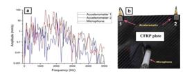
(a) Auto-spectrum plot of the experimental free vibration test, (b) typical impact vibration test, and the vibration sensors' mounting method.

3.6 Damaged CFRP Composite Evaluation using FEA
Under this category, three scenarios were carried out, depending on crack orientation. Horizontal, vertical, and diagonal cracks were developed. Variations in the cracks’ lengths and widths were modeled via parametric investigation methods to examine the impact of crack design on the dynamic properties. Fig. 15 shows the effect of crack orientation on the resonant frequencies with their corresponding modes. The results were gathered at fixed crack dimensions of 150×1mm. The pristine CFRP sheet simulation returned higher frequencies at each mode, while the damaged composite sheets had lower resonance frequencies. In the horizontal crack case, the damaged CFRP sheets had a noticeably lower resonant frequency at the higher modes.

3.6.1 Effect of Crack Orientation on the Dynamic Properties
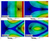
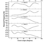
The FEA showed the effect of damage orientation on the resonant frequencies and their corresponding mode numbers. The mode shape most affected by the damage was the fifth mode, as shown in Fig. 16. A crack perpendicular to the clamp position was the most influential damage. Fig. 17 shows the resonant frequency variations through different crack angle orientations (0° to 90°). The parametric study was carried out at fixed crack dimensions of 150×1mm. The results showed that the resonant frequency variation was limited, especially in mode numbers 1 and 2, while there was significant variation at the higher modes (3, 4, and 5). Mode number 3 was influenced by the damage orientation angle; as the crack angle increased, the resonant frequency decreased. On the contrary, in mode number 4, the resonant frequency increased as the crack orientation angle increased from 0° to 90°.

FE simulation model of the first five-mode shapes and the effect of damage orientation on the CFRP plate; a) vertical crack, b) horizontal crack, c) diagonal crack
3.6.2 Effect of Laminate Layup Orientation on the Resonant Frequency
Most commercial carbon fibre composites are fabricated using 0/90 layups and 0/90_45/-45 quasi-isotropic laminate. There were some fluctuations in the resonant frequency at each simulated mode shape, and this can be attributed to the layup orientation of the laminated fibre when the crack width increased. These resonant frequency fluctuations appeared clearly in the 0/90 layup composite, while the 0/90_45/-45 quasi-isotropic laminate showed less variation. Fig. 18 presents the effect of layup orientation angle on the dynamic behaviour of the carbon fibre composite. The large fluctuation of the resonant frequencies in the 0/90 layup composite can be explained by the fact that the crack width increased in a region without the reinforced carbon fibre. When the crack’s width increased, it intersected with carbon fibre reinforcements, causing the resonant frequency change. Table 3 lists the fluctuation percentages in the three investigated laminate layup composites. The minimum resonant frequency variation was observed in the 0/90 layups type. The 0/90_45/-45 and 0/90_45/-45_30/-30 quasi-isotropic laminates showed minimum resonant frequency fluctuations throughout all simulated mode shape numbers. The quasi-isotropic laminate orientation also increased the value of the resonant frequency by 0.9%, 1.2%, 1.26%, and 2.21% for modes 1, 2, 3, and 4, respectively.
3.6.3 Measuring the Effect of Damage Width on Resonant Frequency via FEA
The damage width was investigated in three crack types: 0°, 45°, and 90° orientations. The results of the FEA parametric study showed that crack width did not influence resonant frequency. The damage's width can influence the resonant frequency only when that width exceeds the composite’s limits, significantly changing the composite structure's mass. Fig. 19 shows the variations (explained in Section 4.3.2) in the first five-mode shapes' resonant frequency values. The variations, however, were no greater than 2.85%; hence, this percentage did not affect the overall results.
Table 4 illustrates the effect of crack orientation on resonant frequency and the corresponding damping ratio. The results were calculated from the experimental data acquired via the free vibration test and processed using the MEscope analysis software. A direct relationship was found between damping ratio and crack orientation. The damping ratio for the pristine plate was lower through the fourth mode shape. The crack orientation was affected by the plate mounting method, and the location of the damage significantly affected the dynamic properties of the CFRP composite. The vertical damage (90°) and the damage perpendicular to the mounting location produced lower resonant frequencies through all mode shapes. The damping ratio was also influenced by the damage type and increased, as illustrated by the time decay curve in Fig. 20.
Fig. 21 shows the experimental investigation's waterfall plot using the FRF to determine the effect of crack orientation on the CFRP composites. The pristine plate showed minimum resonant frequencies over time. It exhibited no apparent resonant frequency between 1,300 and 5,000Hz, while the damaged CFRP composite sheets had remarkable resonant frequencies in the same region. The existence of these frequencies was attributed to a change in the composite structures caused by the damage. Thus, the damage changed the composite’s dynamic behaviour.

Effect of laminate layup orientation on the resonant frequency fluctuations of CFRP through the fourth mode shape.


Experimental time decay curve of the pristine plate and of the diagonal and vertical crack orientations

3.6.4 Effect of Crack Length on Dynamic Properties
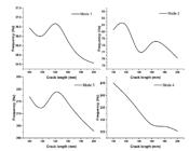
Crack length significantly affected the composites’ structure and dynamic properties. Fig. 22 shows the effect of crack length on the corresponding natural frequency across the nine investigated mode shapes. The numerical model's parametric study results showed that increasing the length of the crack caused the natural frequency values to decrease for all mode shapes. Thus, it became clear that the frequencies of the first mode shape, in all cases studied, were convergent and, therefore, were unreliable for assessing the cracked CFRP composite structure. The vertical crack had the most influence on the natural frequency results across all mode shapes. The numerical simulation results showed a significant decrease in frequency value corresponding to each mode.
4 Conclusion
In the current investigation, various types of cracks were created in CFRP composites to identify the orientation of critical damage in the structure. From this, the following conclusions were drawn.
The experimental, multi-sensor vibration analysis efficiently detected the CFRP composite cracks by averaging the measurements for measuring damage. It was also noteworthy that, at higher modes, the frequency components were suitable for detecting CFRP structure damage. The orientation of the damage or cracks significantly affected the dynamic properties of CFRP composites. The vertical crack had the greatest influence on the eigenvalues of the mode shape frequencies. The damage width does not significantly affect the value of dynamic properties; hence the results reveal that the variation in all resonant frequencies for different dimensions of the designed crack widths does not exceed 2.85%.
FRF analysis revealed several higher frequencies after 1kHz in the cracked CFRP composite structure, while the pristine structure showed lower (or no) values at such frequencies. The propagated crack's width did not significantly affect the resonant frequency values across the examined mode shapes. In contrast, the length of the crack had a major impact on the composites’ dynamic properties.
The experimental dynamic properties of the investigated CFRP composites were consistent with the results of the numerical model. The laminate layup orientation significantly affected the stability of the resonant frequency at each mode shape. The 0/90 layup laminate composite showed more fluctuated values than did the 0/90_45/-45 quasi-isotropic laminate composite. The damping ratio was an effective method for differentiating between pristine and cracked CFRP composites via the changed damping ratio value. Furthermore, the crack's orientation with respect to impact excitation has a significant effect on the damping capacity value; hence, it can reach 2.5 times if the crack was perpendicular to the impact point location on the structure. The current technique can be applied to various types of composites containing laminates, but the excitation direction regarding crack orientation can affect the dynamic results.
Acknowledgement
This work was supported by the Deanship of Scientific Research (DSR), King Abdulaziz University, Jeddah under grant No. (G-632-135-39). The authors therefore gratefully acknowledge technical and financial support from DSR.
References
- AbuShanab, W. S. and E. B. Moustafa (2018). “Detection of Friction Stir Welding Defects of AA1060 Aluminum Alloy Using Specific Damping Capacity.” Materials (Basel, Switzerland) 11(12): 2437.
- Berthelot, J.-M., M. Assarar, Y. Sefrani and A. E. Mahi (2008). “Damping analysis of composite materials and structures.” Composite Structures 85(3): 189-204.
- Cawley, P. and R. D. Adams (1979a). “The location of defects in structures from measurements of natural frequencies.” The Journal of Strain Analysis for Engineering Design 14(2): 49-57.
- Cawley, P. and R. D. Adams (1979b). “A Vibration Technique for Non-Destructive Testing of Fibre Composite Structures.” Journal of Composite Materials 13(2): 161-175.
- Chouinard, L., V. Shahsavari and J. Bastien (2019). “Reliability of Wavelet Analysis of Mode Shapes for the Early Detection of Damage in Beams.” Frontiers in Built Environment 5(91).
- Della, C. N. and D. Shu (2005). “Free vibration analysis of composite beams with overlapping delaminations.” European Journal of Mechanics - A/Solids 24(3): 491-503.
- Ding, G., C. Xie, J. Zhang, G. Zhang, C. Song and Z. Zhou (2015). “Modal analysis based on finite element method and experimental validation on carbon fibre composite drive shaft considering steel joints.” Materials Research Innovations 19(sup5): S5-748-S745-753.
- El-Hafidi, A., P. B. Gning, B. Piezel, M. Belaïd and S. Fontaine (2017). “Determination of dynamic properties of flax fibres reinforced laminate using vibration measurements.” Polymer Testing 57: 219-225.
- Erkliğ, A., M. Bulut and E. Yeter (2012). “Effects of cutouts on natural frequency of laminated composite plates.” Science and Engineering of Composite Materials 0(0): 1-7.
- Hammad, A. H. and E. B. Moustafa (2020). “Study some of the structural, optical, and damping properties of phosphate glasses containing borate.” Journal of Non-Crystalline Solids 544: 120209.
- Hu, H., B.-T. Wang, C.-H. Lee and J.-S. Su (2006). “Damage detection of surface cracks in composite laminates using modal analysis and strain energy method.” Composite Structures 74(4): 399-405.
- Iezzi, F., C. Valente and F. Brancaleoni (2020). Experimental Validation of Damage Indices Based on Complex Modes for Damage Detection in Vibrating Structures. Proceedings of the 13th International Conference on Damage Assessment of Structures, Singapore, Springer Singapore.
- Iliopoulos, S., D. G. Aggelis, L. Pyl, J. Vantomme, P. Van Marcke, E. Coppens and L. Areias (2015). “Detection and evaluation of cracks in the concrete buffer of the Belgian Nuclear Waste container using combined NDT techniques.” Construction and Building Materials 78: 369-378.
- Kyriazoglou, C., B. H. Le Page and F. J. Guild (2004). “Vibration damping for crack detection in composite laminates.” Composites Part A: Applied Science and Manufacturing 35(7): 945-953.
- Maia, N. M. S., J. M. M., Almas, E. A. M., Sampaio, R. P. C. (2003). “Damage detection in structures: From mode shape to frequency response function methods.” Mechanical Systems and Signal Processing 17(3): 489-498.
- Manoach, E., S. Samborski, A. Mitura and J. Warminski (2012). “Vibration based damage detection in composite beams under temperature variations using Poincaré maps.” International Journal of Mechanical Sciences 62(1): 120-132.
- Manoach, E., J. Warminski, L. Kloda and A. Teter (2016). “Vibration Based Methods For Damage Detection In Structures.” MATEC Web Conf. 83.
- Mohan, A. and S. Poobal (2018). “Crack detection using image processing: A critical review and analysis.” Alexandria Engineering Journal 57(2): 787-798.
- Moustafa, E. B. (2018). “Dynamic Characteristics Study for Surface Composite of AMMNCs Matrix Fabricated by Friction Stir Process.” Materials (Basel) 11(7).
- Muhammet Raci Aydın, M. R. A., Ö. G. Ömer Gündoğdu, B. K. Barbaros Kaya, G. B. Gürbüz Bayraktar, O. K. A. Okan Kaan Aksuoğlu and O. K. A. Okan Kaan Aksuoğlu (2018). “Effect of Orientation Angles on Vibration Properties at Carbon Fiber Reinforced Polymeric Composites.” E-Journal of New World Sciences Academy 13(3): 180-189.
- Murčinková, Z., I. Vojtko, M. Halapi and M. Šebestová (2019). “Damping properties of fibre composite and conventional materials measured by free damped vibration response.” Advances in Mechanical Engineering 11(5): 1687814019847009.
- Ngo-Cong, D., N. Mai-Duy, W. Karunasena and T. Tran-Cong (2011). “Free vibration analysis of laminated composite plates based on FSDT using one-dimensional IRBFN method.” Computers & Structures 89(1): 1-13.
- Ostachowicz, W. M. and M. Krawczuk (1990). “Vibration analysis of a cracked beam.” Computers & Structures 36(2): 245-250.
- P. Nagasankar, S. B. P., R. Velmurugan (2012). “The Influence of the Different Fiber lay-ups on the Damping Characteristics of Polymer Matrix Composite.” Journal of Applied Sciences 12: 1071-1074.
- Pei, X. Y. and J. L. Li (2012). “The Effects of Fiber Orientation on the Vibration Modal Behavior of Carbon Fiber Plain Woven Fabric/Epoxy Resin Composites.” Advanced Materials Research 391-392: 345-348.
- Pereira, G. F., L. P. Mikkelsen and M. McGugan (2015). “Crack Detection in Fibre Reinforced Plastic Structures Using Embedded Fibre Bragg Grating Sensors: Theory, Model Development and Experimental Validation.” PloS one 10(10): e0141495-e0141495.
- Razvan, A., C. E. Bakis and K. L. Reifsnider (1990). “SEM investigation of fiber fracture in composite laminates.” Materials Characterization 24(2): 179-190.
- Romhány, G., T. Czigány and J. Karger-Kocsis (2017). “Failure Assessment and Evaluation of Damage Development and Crack Growth in Polymer Composites Via Localization of Acoustic Emission Events: A Review.” Polymer Reviews 57(3): 397-439.
- Rueppel, M., J. Rion, C. Dransfeld, C. Fischer and K. Masania (2017). “Damping of carbon fibre and flax fibre angle-ply composite laminates.” Composites Science and Technology 146: 1-9.
- Sun, Z., J. Xiao, X. Yu, R. Tusiime, H. Gao, W. Min, L. Tao, L. Qi, H. Zhang and M. Yu (2020). “Vibration characteristics of carbon-fiber reinforced composite drive shafts fabricated using filament winding technology.” Composite Structures 241.
- Tsai, J.-L. and Y.-K. Chi (2008). “Effect of fiber array on damping behaviors of fiber composites.” Composites Part B: Engineering 39(7): 1196-1204.
- Utomo, J. T., D. D. Susilo and W. W. Raharja (2017). The influence of the number and position of the carbon fiber lamina on the natural frequency and damping ratio of the carbon-glass hybrid composite.
- Wang, Q., B. Qin, D. Shi and Q. Liang (2017). “A semi-analytical method for vibration analysis of functionally graded carbon nanotube reinforced composite doubly-curved panels and shells of revolution.” Composite Structures 174: 87-109.
- Wen, J., Z. Xia and F. Choy (2011). “Damage detection of carbon fiber reinforced polymer composites via electrical resistance measurement.” Composites Part B: Engineering 42(1): 77-86.
- Wen Jie, X. Z., Choy Fred (2011). “Damage detection of carbon fiber reinforced polymer composites via electrical resistance measurement.” Composites Part B: Engineering 42(1): 77-86.
- Wright, G. C. (1972). “The dynamic properties of glass and carbon fibre reinforced plastic beams.” Journal of Sound and Vibration 21(2): 205-212.
- Yan, Y. J. and L. H. Yam (2002). “Online detection of crack damage in composite plates using embedded piezoelectric actuators/sensors and wavelet analysis.” Composite Structures 58(1): 29-38.
- Yu, J., Y. Z. Liu and R. R. Shi (2009). “Studies on Crack Propagation of Carbon Fiber Reinforced Epoxy Resin Composite.” Advanced Materials Research 79-82: 1029-1033.
Edited by
Editor:
Publication Dates
-
Publication in this collection
23 Apr 2021 -
Date of issue
2021
History
-
Received
15 Oct 2020 -
Reviewed
19 Dec 2020 -
Accepted
22 Feb 2021 -
Published
25 Feb 2021


