Abstract
In this paper, dynamic analysis of two different weapon systems (35 mm Anti-Aircraft Barrel (AAB) and 120 mm Grooved Tank Barrel (GTB)) under the effect of statically unbalanced projectile has been performed with a new 12 DOF 3-D element technique using Finite Element Method (FEM). The muzzle deviations, which negatively affect the barrel shooting accuracy at firing, are calculated in a time dependent manner using Newmark β algorithm with high accuracy at both axes (y and z) considering the Coriolis centripedal and centrifugal forces. The effect of such fundamental physical parameters as shift from rotating center and angular velocity belonging to the unbalanced projectile on barrel dynamics are analyzed with this new and affective FEM. As a result, it was found out that 1% of a millimeter shift from projectile belonging to a weapon system leads to excessive vibration on both axes and compromises the shooting accuracy of the barrel.
Keywords
Vibration of gun barrels; FEM; 2-D vibration; 3-D element; unbalanced projectile; fire accuracy; weapons
1 INTRODUCTION
Dynamic analysis of engineering structures under the effect of moving loads is a fundamental issue in several branches, especially defense industry, transportation systems, manufacturing industry and machine design, and has been studied by many researchers. Some studies which dealt with the analysis of dynamic behaviors of structures under the effect of moving loads are given in (L. Fryba, 1999L. Fryba, 1999. Vibration solids and structures under moving loads. Thomas Telford House.; Oguamanam and Hansen, 1998Oguamanam, D.C.D., Hansen, J.S., 1998. Dynamic Response of an Overhead Crane System. J. Sound Vib. 213, 889-906. doi:10.1006/jsvi.1998.1564
https://doi.org/10.1006/jsvi.1998.1564...
). The study which analyses the dynamic behavior of Timoshenko beam under the effect of moving loads can be found in (Lee, 1996Lee, H.P., 1996. Transverse vibration of a Timoshenko beam acted on by an accelerating mass. Appl. Acoust. doi:10.1016/0003-682X(95)00067-J
https://doi.org/10.1016/0003-682X(95)000...
; T. V. Lien et al., 2017T. V. Lien, N. T. Duc, N. T. Khiem, 2017. Mode Shape Analysis of Multiple Cracked Functionally Graded Timoshenko Beams. Lat. Am. J. Solids Struct. 14, 1327-1344. doi:10.1590/1679-78253496
https://doi.org/10.1590/1679-78253496...
). The FEM studies which took the moving load on structures as a moving mass model as a result of which are conducted considering the inertia, Coriolis and centripetal forces of the moving mass are given in (Bajer and Dyniewicz, 2009Bajer, C.I., Dyniewicz, B., 2009. Virtual functions of the space-time finite element method in moving mass problems. Comput. Struct. 87, 444-455. doi:http://dx.doi.org/10.1016/j.compstruc.2009.01.007
https://doi.org/10.1016/j.compstruc.2009...
; Dehestani et al., 2009Dehestani, M., Mofid, M., Vafai, A., 2009. Investigation of critical influential speed for moving mass problems on beams. Appl. Math. Model. 33, 3885-3895. doi:10.1016/j.apm.2009.01.003
https://doi.org/10.1016/j.apm.2009.01.00...
; Esen, 2017Esen, I., 2017. A modified FEM for transverse and lateral vibration analysis of thin beams under a mass moving with a variable acceleration. Lat. Am. J. Solids Struct. 14, 485-511. doi:10.1590/1679-78253180
https://doi.org/10.1590/1679-78253180...
, 2011Esen, I., 2011. Dynamic response of a beam due to an accelerating moving mass using moving finite element approximation. Math. Comput. Appl. 16, 171-182., 2015Esen, Ý., 2015. A new FEM procedure for transverse and longitudinal vibration analysis of thin rectangular plates subjected to a variable velocity moving load along an arbitrary trajectory. Lat. Am. J. Solids Struct. 12, 808-830., 2013Esen, Ý., Koç, M.A., 2013. Dynamics of 35 mm anti-aircraft cannon barrel durig firing, in: International Symposium on Computing in Science & Engineering. Aydýn, pp. 252-257.; Kahya, 2012Kahya, V., 2012. Dynamic analysis of laminated composite beams under moving loads using finite element method. Nucl. Eng. Des. 243, 41-48. doi:10.1016/j.nucengdes.2011.12.015
https://doi.org/10.1016/j.nucengdes.2011...
; Wu et al., 2000Wu, J., Whittaker, A., Cartmell, M., 2000. The use of finite element techniques for calculating the dynamic response of structures to moving loads. Comput. Struct. 78, 789-799. doi:http://dx.doi.org/10.1016/S0045-7949(00)00055-9
https://doi.org/10.1016/S0045-7949(00)00...
). Inertia effect of moving load is an essential point in bridge dynamics, railed system transportation and the design of high-velocity processing tools which is examined in detail in studies (Dehestani et al., 2009Dehestani, M., Mofid, M., Vafai, A., 2009. Investigation of critical influential speed for moving mass problems on beams. Appl. Math. Model. 33, 3885-3895. doi:10.1016/j.apm.2009.01.003
https://doi.org/10.1016/j.apm.2009.01.00...
; Michaltsos, 2002Michaltsos, G., 2002. Dynamic behaviour of a single-span beam subjected to loads moving with variable speeds. J. Sound Vib. 258, 359-372. doi:10.1006/jsvi.5141
https://doi.org/10.1006/jsvi.5141...
; Michaltsos et al., 1996Michaltsos, G., Sophianopoulos, D., Kounadis, A.N., 1996. The Effect of a Moving Mass and Other Parameters on the Dynamic Response of a Simply Supported Beam. J. Sound Vib. 191, 357-362. doi:10.1006/jsvi.1996.0127
https://doi.org/10.1006/jsvi.1996.0127...
). The final solutions of moving mass problems has been made easier by using computer technology, and an effort for comparing the dynamic answer of a simply supported beam using different numerical methods is given in (Bulut and Kelesoglu, 2010Bulut, H., Kelesoglu, O., 2010. Comparing numerical methods for response of beams with moving mass. Adv. Eng. Softw. 41, 976-980. doi:10.1016/j.advengsoft.2010.05.006
https://doi.org/10.1016/j.advengsoft.201...
). One of the important application fields of moving load problems is vehicle-bridge interaction (VBA) and a study which handles the interaction between a semi-vehicle model with six freedom degrees with passenger and driver seats and a simply supported bridge beam with normal section in terms of passenger comfort is given in (Esmailzadeh and Jalili, 2003Esmailzadeh, E., Jalili, N., 2003. Vehicle-passenger-structure interaction of uniform bridges traversed by moving vehicles. J. Sound Vib. 260, 611-635. doi:10.1016/S0022-460X(02)00960-4
https://doi.org/10.1016/S0022-460X(02)00...
). Other studies on VBA are given in (Koç and Esen, 2017Koç, M.A., Esen, Ý., 2017. Modelling and analysis of vehicle-structure-road coupled interaction considering structural flexibility, vehicle parameters and road roughness †. J. Mech. Sci. Technol. 31, 1-18. doi:10.1007/s12206-017-0913-y
https://doi.org/10.1007/s12206-017-0913-...
; S. Talukdar and Lalthlamuana, 2016S. Talukdar, Lalthlamuana, R., 2016. Identification of flexible vehicle parameters on bridge using particle filter method. Struct. Eng. Mech. 57, 21-43.; Wyss et al., 2011Wyss, J.C., Su, D., Fujino, Y., 2011. Prediction of vehicle-induced local responses and application to a skewed girder bridge. Eng. Struct. 33, 1088-1097. doi:10.1016/j.engstruct.2010.12.020
https://doi.org/10.1016/j.engstruct.2010...
).
Another important application field of moving load problems is defense industry where it is widely used in determining the barrel vibrations caused by the interaction between the barrel and moving projectile. Some studies modelled using FEM are given in (Esen and Koç, 2015aEsen, Ý., Koç, M.A., 2015a. Dynamic response of a 120 mm smoothbore tank barrel during horizontal and inclined firing positions. Lat. Am. J. Solids Struct. 12, 1462-1486., 2015bEsen, Ý., Koç, M.A., 2015b. Optimization of a passive vibration absorber for a barrel using the genetic algorithm. Expert Syst. Appl. 42, 894-905. doi:10.1016/j.eswa.2014.08.038
https://doi.org/10.1016/j.eswa.2014.08.0...
, 2013Esen, Ý., 2013. A new finite element for transverse vibration of rectangular thin plates under a moving mass. Finite Elem. Anal. Des. 66, 26-35. doi:10.1016/j.finel.2012.11.005
https://doi.org/10.1016/j.finel.2012.11....
; Koç et al., 2016Koç, M.A., Esen, Ý., Çay, Y., 2016. Tip deflection determination of a barrel for the effect of an accelerating projectile before firing using finite element and artificial neural network combined algorithm. Lat. Am. J. Solids Struct. 13, 1968-1995. doi:http://dx.doi.org/10.1590/1679-78252718
https://doi.org/10.1590/1679-78252718...
) which deal with the dynamic interaction between barrel and projectile. The upside and downside movement of the barrel tip caused by the movement of projectile in the barrel has a negative effect on the shooting accuracy of the weapon system (Gimm et al., 2012Gimm, H.I., Cha, K.U., Cho, C.K., 2012. Characterizations of gun barrel vibrations of during firing based on shock response analysis and short-time Fourier transform. J. Mech. Sci. Technol. 26, 1463-1470. doi:10.1007/s12206-012-0335-5
https://doi.org/10.1007/s12206-012-0335-...
; Littlefield et al., 2002bLittlefield, A.G., Kathe, E.L., Durocher, R., 2002b. Dynamically tuned shroud for gun barrel vibration attenuation. Smart Struct. Mater. 2002: Damping Isol. 4697, 89-97. doi:10.1117/12.472645
https://doi.org/10.1117/12.472645...
). The researcher has studied the eight degree of freedom model of a weapon system with its body, and analyzed the vibration of its barrel (Balla, 2011Balla, J., 2011. Dynamics of mounted automatic cannon on track vehicle. Int. J. Math. Model. Methods Appl. Sci. 5,423-432. ). Effect of stepped barrels on the stability and the dynamics of barrels have been investigated by (Tawfik, 2008Tawfik, M., 2008. Dynamics and Stability of Stepped Gun-Barrels with Moving Bullets. Adv. Acoust. Vib. 2008, 1-6. doi:10.1155/2008/483857
https://doi.org/10.1155/2008/483857...
). A study where an ABAQUS finite element model was created in order to model the interaction between projectile and the barrel in a 155 mm developed weapon system and the results are compared to experimental work is given in (Alexander, 2007Alexander, E.J., 2007. AGS Gun and Projectile Dynamic Modeling Correlation to Test Data Branch Manager, Applied Mechanics. US Army Armament Syst. Div. 480-496.; Ding et al., 2017Ding, C., Liu, N., Zhang, X., 2017. A mesh generation method for worn gun barrel and its application in projectile-barrel interaction analysis. Finite Elem. Anal. Des. 124, 22-32. doi:10.1016/j.finel.2016.10.003
https://doi.org/10.1016/j.finel.2016.10....
). A comprehensive literature study conducted with the purpose of modelling and controlling the vibration of main battle tanks can be found in (Dursun et al., 2017Dursun, T., Büyükcivelek, F., Utlu, Ç., 2017. A review on the gun barrel vibrations and control for a main battle tank. Def. Technol. 13, 353-359. doi:10.1016/j.dt.2017.05.010
https://doi.org/10.1016/j.dt.2017.05.010...
). Researchers (Kathe, 1997Kathe, E., 1997. Design and validation of a gun barrel vibration absorber. New York.) have studied the dynamics of barrels and pro- posed a muzzle-brake for reducing the tip-deflection of a 120 mm-cannon-barrel. It was reported that, the muzzle-brake, working as a passive vibration absorber, could reduce the deflection of the barrel by about half. Other studies on reducing the barrel vibrations caused by the interaction between barrel and projectile can be found in (Esen and Koç, 2015bEsen, Ý., Koç, M.A., 2015b. Optimization of a passive vibration absorber for a barrel using the genetic algorithm. Expert Syst. Appl. 42, 894-905. doi:10.1016/j.eswa.2014.08.038
https://doi.org/10.1016/j.eswa.2014.08.0...
; Hua et al., 2015Hua, H., Liao, Z., Song, J., 2015. Vibration reduction and firing accuracy improvement by natural frequency optimization of a machine gun system. J. Mech. Sci. Technol. 29, 3635-3643. doi:10.1007/s12206-015-0807-5
https://doi.org/10.1007/s12206-015-0807-...
).
When the studies conducted on interaction between barrel and projectile are examined, it can be seen that studying the effect of unbalanced projectile on barrel vibrations ranks among the top topics examined by scientists in terms of static and dynamic. A study which examined the transverse vibrations of barrel tip for a sports rifle barrel under the effect of unbalanced projectile both in static and dynamic terms is given in (Vitek, 2009Vitek, R., 2009. The generally unbalanced projectile load on the sporting rifle barrel. Proc. 8th WSEAS Int. Conf. Syst. Sci. Simul. Eng. 164-169.). The study contains a two-dimensional mathematical model with the purpose of showing the effect of unbalanced projectile on barrel vibrations. However, there is need for a more comprehensive, three-dimensional model in order to analyze the barrel vibrations under the effect of unbalanced projectile as the centrifugal force which affects the barrel by means of the unbalanced projectile which progresses inside the barrel by making both rotating and extrapolation movements will have components in two different directions. In this case, there is need to develop a three-dimensional mathematical model in order to examine the shooting accuracy of weapon barrel.
In this study, the effect of statically unbalanced projectile on barrel shooting accuracy for two different weapon systems such as 35 mm AAB and 120 mm GTB has been analysed using a special programme prepared in MATLAB commercial software, which is a new three-dimensional finite elements technique. In the study, displacements and accelerations at barrel-tip were obtained with high time dependent accuracy in both axes. The effect of basic physical parameters such as axis shift of statically unbalanced projectile on barrel vibrations has been comprehensively studied.
2 MATHEMATICAL MODELLING
2.1 Problem Definition
Projectiles belonging to weapon systems usually are symmetrical in their axis. However, seldom the central inertia principal axis can be shifted at a certain distance from the geometrical central axis. The reason of this asymmetry which can be witnessed in projectiles can be explained by manufacturing tolerances, damages that occur during rough graining, the lack of homogeneity of the material, and changes during the study (abrasion, corrosion, thermal expansion etc.). The unbalance, which occurs due to this asymmetry in projectiles, is evaluated in two groups. The first one is static unbalance, which occurs when the central inertia principal axis of the center of gravity of projectile is parallel to but not overlapping with the geometric central axis. The second is dynamic unbalance which occurs when these two axes are not parallel to each other. In this paper, the effect of unbalanced projectile on the shooting accuracy of barrel has been examined. Figures 1a and 1b gives the front and rear images of a statically unbalanced projectile. As seen in the Figure 1b, centrifugal force has two components in directions y and z. The component y is in the same direction with center of gravity. Its orientation is identical or contrary to the center of gravity during the movement of projectile in the barrel. The force component of centrifugal force in z direction causes the barrel to vibrate in the y direction as well. A projectile which is fully balanced in static and dynamic terms suffers from deviation in barrel tip in the direction of center of gravity whereas a projectile which is unbalanced in static or dynamic terms leads to deviation at barrel tip in both directions.
2.2 Finite element equation of a barrel element under an accelerating statically unbalanced projectile
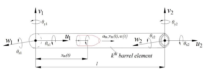
For the interaction of an accelerating statically unbalanced projectile with the mass m p and the barrel, a clamped-free cantilevered Euler-Bernoulli beam shown in Figure 2 is considered. The projectile moves from the left end of barrel to the right end with a variable velocity v(t), and a constant acceleration a c .Figure 3 shows mesh discretion of the barrel-beam under accelerating projectile and absorber, while Figure 4 shows the sth beam element over which the projectile m p passes at time t. The k th barrel element that interacts with projectile has six equivalent nodal forces as well as displacements at each nodal point. The time dependent global position of the projectile inside the barrel is represented by x p(t). The time dependent local position of the projectile inside the finite element is expressed with x m(t). Barrel beam has n number of elements and n+1 nodes.
While the barrel under the effect of statically unbalanced projectile is vibrating in transversal (y,z) and longitudinal (x) directions, time dependent dynamic forces occur between projectile and the barrel, which are expressed as follows considering the transversal and vertical deformations (w y (x,t), w z (x,t)) that occur at the contact point (x) of the projectile on the barrel.
The expressions f x(x,t), f y(x,t) and f z(x,t) in the Eqs. (1a-c) represent the axial, vertical and transversal forces that affect the barrel by projectile at x point in t time inside the barrel respectively. The expressions δ(x-x p ) and g respectively indicate Direc-delta function and gravity acceleration. The rotating moment M x(x,t) created by the unbalanced projectile around the barrel axis (x) which progresses by rotating with fixed acceleration angular velocity ω(t) inside the grooved barrel is expressed as follows:
Modelling of the barrel and projectile interaction using 3-D FEM discretion of the barrel system
Parameters θ x(x,t) and I p given in Eq. (2) represent the mass inertia moment of projectile which shows turning and extrapolation movement at that point and the angular deformation which occurred in the barrel at x position in t time. The time dependent position, velocity and acceleration of unbalanced projectile inside the barrel is expressed as follows:
x0 and v 0 in Eq. (3) respectively represent the initial position of unbalanced projectile at the beginning of analysis (at r=0) and the initial velocity. a c and α c respectively represent the linear and angular fixed acceleration of unbalanced projectile. The inertia effects that emerge along vertical (y) and transversal (z) axes during the movement of unbalanced projectile inside the barrel, namely d2 w y(x p ,t)/dt 2, d2 w z(x p ,t)/dt 2, are calculated by taking second-degree derivatives of w y(x p ,t) and w z(x p ,t) which are barrel dent expressions in the stated directions according to time:
Taking into consideration the one given by Eq. (3), the acceleration expression given by Eq. (4) is written for accelerated and decelerated movements as follows:
Eqs. (5a-b) is written as follows:
The expressions “ ′ ” and “ . ” in Eqs. (6a-b) respectively represent the position-bound and time dependent derivatives of the displacement function. The expressions w y(xp,t) and w z(xp,t) respectively represent the vertical and transversal displacement of the barrel at t time at x point. Parameter θ x(x p,t) represents the angular deformation of the barrel at x p position. In this case, expressions (1a-c) are expressed as follows:
Where expressions , and respectively represent the inertia, centripetal and Coriolis forces. Parameters and represent the components of the centrifugal force of projectile which progresses with both extrapolation and rotation movement in respectively y and z directions. In addition, the expression mg represents the weight force of the unbalanced projectile vertical to axis x.
Using the expression given with Eq. (6b), the moment expression of Eq. (2) is written as follows:
Under the effect of the displacement of the accelerating projectile, the equivalent nodal forces of the k th barrel element can be expressed as follows:
where N
i
(i=1-12) is the hermite shape function of the beam element, as shown below Clough and Penzien (2003Clough R.W; Penzien J., 2003. Dynamics of Structures, Dynamics of Structures. doi:10.1002/9781118599792
https://doi.org/10.1002/9781118599792...
) (Clough R.W; Penzien J., 2003):
The length of the element is l and x
m
(t) is the variable distance between the accelerating projectile and the left end of the k
th element at time t as shown in Figure 3. The relationships between the shape functions and the transverse and longitudinal deflection functions and the nodal displacements of the k
th element at position x
m
(t) at time t are as follows Clough and Penzien (2003Clough R.W; Penzien J., 2003. Dynamics of Structures, Dynamics of Structures. doi:10.1002/9781118599792
https://doi.org/10.1002/9781118599792...
) (Clough R.W; Penzien J., 2003):
When the displacement functions given in Eq. (11) are derived according to time and location, they are entered in Eqs. (9a-d) to obtain the following expressions:
The expressions given in Eqs. (12a-d) are written in the form of a matrix as follows:
The parameters given in the expression in Eqs. (13) as regards mass, damping and pertinacity matrixes belonging to the unbalanced projectile ([m], [c], [k]) are given in additional Appendix A. In addition, the displacement, displacement velocity and acceleration vectors in contact with the unbalanced projectile are expressed as follows:
2.3 The time dependent motion equation of the barrel and projectile system
The motion equation for the system with multiple degrees of freedom including the barrel and accelerating projectile is expressed as follows:
Where are respectively the instantaneous mass, damping, and stiffness matrices of the entire system’s in global coordinate plane. Furthermore, are, respectively, the acceleration, velocity, and displacement vectors of the barrel nodal points on the global coordinate axis. Besides is the overall external force vector of the system at time t.
2.4 The mass and stiffness matrices of the barrel and projectile system under unbalanced projectile
The elemental mass and stiffness matrices K
e and M
e of the each beam elements of the barrel can be obtained using the classical FEM that are widely explained in literature., ie. (Cifuentes, 1989Cifuentes, A.O., 1989. Dynamic response of a beam excited by a moving mass. Finite Elem. Anal. Des. 5, 237-246. doi:10.1016/0168-874X(89)90046-2
https://doi.org/10.1016/0168-874X(89)900...
). When there is an accelerating projectile the mass and stiffness matrices of the projectile, [m] and [k] are summed with the mass and stiffness matrices M and K by taking into account the inertial and centripetal effects. In this case the instantaneous overall stiffness and mass matrices, which are nxn in size, are:
Except for the k th element;
In this context, n represents the total degree of freedom consisting of finite elements after imposing the boundary conditions in Eq.(15).
2.5 The damping matrix of the barrel under the effect of the projectile
The damping matrix is determined using Rayleigh’s damping theory, in which the damping matrix C is proportional to the mass and stiffness matrices. Based on this theory, the following damping matrix is obtained.
The a and b values within Eq. (27a) are obtained by solving the Eq. (27b), (Clough R.W; Penzien J., 2003Clough R.W; Penzien J., 2003. Dynamics of Structures, Dynamics of Structures. doi:10.1002/9781118599792
https://doi.org/10.1002/9781118599792...
) (2003); where æ
i and æ
j are the damping ratios of the structural system for two natural frequencies of ù
i and ù
j. The total instantaneous damping matrix of the damped system under the effect of the accelerating projectile is given by:
Except for the k th element, where
2.6 The global force vector of the system under the effect of the accelerating projectile
The instantaneous overall force vector is also time depended. The coefficients of overall force vector are equal to zero except the nodal forces of the sth barrel element. Thus, the instantaneous overall force vector of entire system becomes as below:
With
Detailed information on the algorithm used in order to obtain the movement equation of the system given in Eq. (15) and Newmark â algorithm used in high-accuracy solution of this movement equation in time area are given in previous studies (Esen and Koç, 2015aEsen, Ý., Koç, M.A., 2015a. Dynamic response of a 120 mm smoothbore tank barrel during horizontal and inclined firing positions. Lat. Am. J. Solids Struct. 12, 1462-1486., 2015bEsen, Ý., Koç, M.A., 2015b. Optimization of a passive vibration absorber for a barrel using the genetic algorithm. Expert Syst. Appl. 42, 894-905. doi:10.1016/j.eswa.2014.08.038
https://doi.org/10.1016/j.eswa.2014.08.0...
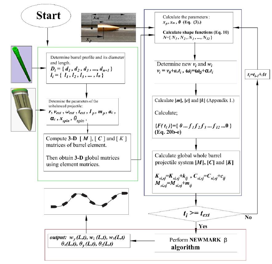
). Simulation procedure belong to study used in this study given by Figure 5.
3 NUMERICAL EXAMPLES
In this section of the study, two different weapon barrels are used in order to test the theoretical model explained in the second section. The first barrel is 35 mm AAB whose barrel profile is shown in Figure 6. In our study, the reason for which this weapon is especially preferred in numerical analysis is that the width of the barrel is very small compared to the length as a result of which it can be well represented by Euler-Bernoulli beam theory explained in section 2. The inside section of this weapon normally lacks grooves but in order to see the effect of unbalanced projectile on z axis it is accepted as grooved.
In firearms groove is a structure designed in order to add rotation movement to the projectile according to the barrel axis as a result of forward movement of the bullet processed helically. This movement adds angular momentum to the projectile and balances it gyroscopically. As a result of a full tour of the projectile by turning in the helically grooved barrel, the axial feed (x spin) progresses for 254 mm. A shorter distance means that projectile will leave the barrel at a higher angular velocity; a longer distance means that it will leave the barrel with lower angular velocity. Accordingly, it is found out that the projectile turns è spin=2ðL/x spin until it leaves the barrel. In this case, the mean angular acceleration of the projectile inside the barrel is determined with ác=2è spin/. Figure 7 shows groove structure of a gun barrel.
The second weapon is a 120 mm grooved tank barrel whose features are given in Table 1. The pressure graph forming inside the barrel at firing shows non-linear action according to time. In this case, the movement acceleration of the projectile inside the barrel will show time dependent and non-linear features. In this study, the movement of projectile inside the barrel has been accepted with mean acceleration in order to avoid the complications caused by variable acceleration. The length of the barrel is given as L, the exit velocity of the projectile from the barrel is expressed as v ext and the mean acceleration of the projectile inside the barrel is given as . In this case, the time of exit of the projectile from the barrel is calculated by or . In this case, considering the information given in Table 1, the acceleration values belonging to 35 mm anti-aircraft bullet and 120 mm tank bullet are determined as (a c)35=2.13x10⁵ m/s2, rad/s2, (a c)120=2.55x10⁵ m/s2, (á c)120=6.31x10⁶ rad/s2 respectively and the time of exit of projectiles from barrel are determined as (t ext)35=0.0055, (t ext)120=0.0069 s, respectively. So, angular velocity of the unbalanced projectiles are respectively for 35 mm AAB and 120 mm GTB at time t ext.
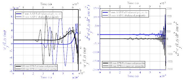
Figure 8a gives the time dependent change of dent amount of barrel tip at y-axis for 35 mm AAB and 120 mm GTB weapons in comparison to the fully balanced and unbalanced projectile. As seen in the figure, maximum displacement at barrel tip at fully balanced projectile for 35 m AAB is 3.31x10⁻⁷ m where the projectile is at 87% barrel distance. The maximum barrel-tip displacement in unbalanced projectile occurred at 8.85x10⁻⁷ m when the projectile was at 48% barrel distance. It is clearly seen that at the weapon barrel-tip under unbalanced projectile effect in static terms there is 167% increase compared to fully balanced projectile model. This increase in barrel-tip can be explained as follows: when the barrel is under the effect of fully balanced projectile, four forces influence at y-axis. The first one of these factors is shown in Eq. (1b) as negative-direction weight force () of projectile which vertically affects the barrel axis. The others are inertia, centripedal and Coriolis forces, which occur due to the action of projectile through barrel beam curvature. These two forces affect the barrel both in identical and opposite directions during the movement of projectile inside the barrel. This is totally related to the movement frequency of the projectile and the natural frequency of the barrel. If the projectile moving inside the barrel is unbalanced, weapon barrel becomes exposed to a fifth force in addition to the four forces mentioned above. This force is expressed as centrifugal force and is given in Eq. (1b) . Centrifugal force has two components. One of these components is in the direction of y-axis () whereas the other is in the direction of z-axis (). The direction of y component of centrifugal force can be both in downwards and upwards direction, which is similar to the inertia, force. Therefore, the force in y direction, which affects the barrel elements under the effect of unbalanced projectile, is a combination of these five forces and the combined force value increased according to the fully balanced projectile model.
Figure 8a gives the change in time in barrel tip dent under the effect of fully balanced and unbalanced projectiles for 120 mm GTB for the same time period. Here, maximum measurement amount at barrel tip in fully balanced projectile is 2.47x10⁻⁷ m when projectile is at 74% barrel distance. Under the effect of unbalanced projectile, maximum barrel-tip dent occurs at 6.405x10⁻⁷ m when projectile is at 23% barrel distance. Figure 8b shows the time dependent change of barrel-tip acceleration for two different weapons systems under balanced and unbalanced projectile. Due to the z component of centrifugal force, weapon barrel begins to vibrate in the direction of z-axis and projectile moves along the curvature of the barrel. Figure 9 shows the time dependent change in displacement that occurs in the direction of z-axis of the barrel tip under the effect of unbalanced projectile.
In Figure 10a and 10b, the relative graphics of acceleration and displacement of the barrel-tips of 35 mm AAB and 120 mm GTB weapon systems under the effect of unbalanced projectile at y and z-axes are shown. If the projectile moving inside the barrel were a fully balanced one, the only vibration at the barrel tip would be in y direction. Unbalanced projectile forces the barrel to vibrate along both y and z-axes. In this case, the barrel tip rotates around both y and z-axes. Figure 11a and 11b respectively show the relative graphics of acceleration and angular displacement of the barrel-tips around y and z-axes under the effect of unbalanced projectile.
The barrel tip value on vertical y direction for gravitational center of the projectile from rotation axis r=0.01 mm using 35 mm AAB and 120 mm GTB. a-) displacement (m) b-) accelerations (m/s2).
The barrel tip deflection on vertical z direction for gravitational center of the projectile from rotation axis r=0.01 mm.
The relative graphics of barrel tip values in both axes (y,z) effect on unbalanced projectile for 35 mm AAB and 120 mm GTB and considering gravitational center of the projectile from rotation axis r=0.01 mm a-) displacement (m), b-) acceleration (m/s2).
The relative graphics of barrel tip according to rotation around z and y axes, effect on unbalanced projectile for 35 mm AAB and 120 mm GTB considering gravitational center of the projectile from rotation axis r=0.01 mm a-) rotation (rad), b-) angular acceleration (rad/s2).
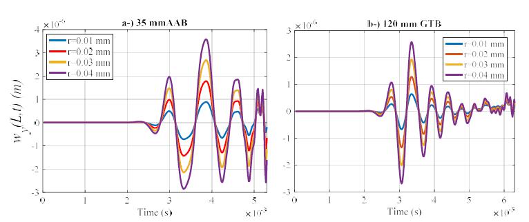
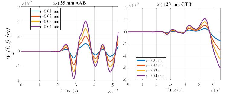
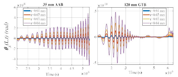
When the expressions given in Eqs. (9b-c) explained in second section are examined, it can be seen that the knot forces applied by statically unbalanced projectile in a certain t time on the relevant barrel element is dependent on the shift of center of gravity of projectile from rotating center, r. Figure 12 shows the effect of r parameter on the amount of dent of barrel-tips along y axis for 35 mm AAB and 120 mm GTB weapons. In these analyses, barrel-tip dent has been shown for four different axis shift distance (r=0.01, 0.02, 0.03, 0.04 mm). As can be seen in the figures, the amplitude of vibrations increase with the amount of axis shift for both weapon systems but no change has occurred in the frequency. Similarly, Figure 13 shows the effect of shift from rotating axis of the projectile center of gravity on the displacement and acceleration, which occur on the barrel-tip z-axis. A similar result has been obtained here. Figures 14a and b show the barrel-tip rotating level around x-axis for different r distances for 35 mm AAB and 120 mm GTB, respectively.
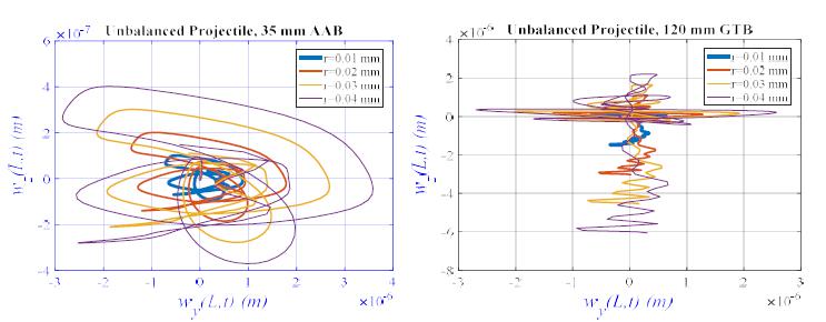
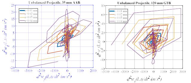
Figures 15a-b shows the relative graphics of dent at y and z-axes, which occur at the barrel-tip at different axis, shift distances for two different weapons systems, namely 35 mm AAB and 120 mm GTB. Figures 16a and b shows the same analysis for barrel-tip accelerations. In both analyses, it is clearly seen that as the axis shift amount r grows, so does barrel-tip deviations in both axes.
The effect of gravitational center of the unbalanced projectile from rotation axis r upon barrel tip deflection on y direction for a-) 35 mm AAB, b-) 120 mm GTB.
The effect of gravitational center of the unbalanced projectile from rotation axis r upon barrel tip deflection on z direction for a-) 35 mm AAB, b-) 120 mm GTB.
The effect of gravitational center of the unbalanced projectile from rotation axis r upon barrel tip rotation around x axis for a-) 35 mm AAB, b-) 120 mm GTB.
The relative graphics of barrel tip displacements in both axes (y,z) effect on unbalanced projectile considering different gravitational center of the projectile from rotation axis (r=0.01, 0.02, 0.03, 0.04 mm), a-) 35 mm AAB, b-) 120 mm GTB.
The relative graphics of barrel tip accelerations in both axes (y,z) effect on unbalanced projectile considering different gravitational center of the projectile from rotation axis (r=0.01, 0.02, 0.03, 0.04 mm), a-) 35 mm AAB, b-) 120 mm GTB.
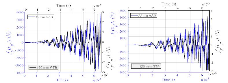
Figures 17a and 17b give the time dependent change of forces that affect in the direction of y and z-axes respectively at the knot points of instant finite element by unbalanced projectile during the time dependent movement of projectile inside the barrel of two different weapons systems, namely 35 mm AAB and 120 mm GTB. As can be seen in the figures, it is seen that the forces which affect the barrel by the projectile in both directions increases as the projectile approaches the barrel-tip. This is due to the fact that the increase in linear and angular velocity of the projectile towards the barrel-tip increases inertia, centripedal, Coriolis and centrifugal forces. The barrel is under the effect of these five forces applied by the projectile: the first one of them is the gravity caused by the weight of the projectile, inertia which is applied by the projectile which vibrates in the direction of y axis and moves along the barrel curvature, Coriolis and centripedal forces and the y component of centrifugal force which is applied by unbalanced projectile. The forces which are applied by the projectile along the z-axis of the barrel are the three forces created due to the bending in that direction and the z component of the centrifugal force created by unbalanced projectile.
The nodal forces of the barrel element on which the unbalanced projectile moving for gravitational center of the projectile from rotation axis r=0.01 mm, a-) y direction, b-) z direction.
4 CONCLUSIONS
Manufacturing tolerances, damages in grain rolling processes, and non-homogeneous distribution of material can lead to static and dynamic unbalances in projectiles. This unbalance leads to the creation of vibrations which negatively affect the shooting accuracy of the barrel especially by the projectile which progresses inside the barrel by conducting both rotation and translation motion. Dynamic analysis of weapon systems under the effect of unbalanced projectile plays an essential role in terms of accurate determination of the shooting accuracy of these weapon systems. However, literature shows that 2-D FEM models developed considering axial and transverse vibrations of the barrel are not adequate in the identification of barrel tip deviations caused by unbalanced projectiles. In this study, the effect of statically unbalanced projectile on the transverse vibrations of the barrel are analyzed for two different weapon systems (35 mm AAB and 120 mm GTB) using a new 3-D 12 DOF FEM and Newmark â algorithm with high accuracy in time zone
Statically unbalanced projectile has excessive effect on the barrel tip vibrations in both axis. For example, if the inertia axis of the weight center of projectile is 1% of a millimeter deviated from the geometric axis, the barrel suffers from 167% more displacement of barrel tip at y axis for 35 mm AAB weapon and 159,3% more displacement for 120 mm GTB. In addition, unbalanced projectile also affected the position of barrel projectile where maximum barrel tip displacement occurred. For example, maximum barrel tip displacement in fully balanced projectile model occurred at 87% barrel distance for 35 mm AAB weapon whereas this value became 48% for unbalanced projectile. The same analysis revealed 74% and 23% values respectively when applied to 120 mm GTB. It is observed that unbalanced projectile excessively increased both barrel tip displacements and barrel tip accelerations. The effect on barrel tip vibrations of r parameter, one of the basic physical parameters of unbalanced projectile, which is the mismatch ratio from geometric central axis of the central inertia axis belonging to the weight center of projectile, has been examined in detail. As a result, it is observed that an increase in the axis mismatch ratio increases both barrel tip displacements and accelerations in both weapon systems excessively.
Fading of these vibrations which negatively affects the barrel strike accuracy created by unbalanced projectile at horizontal and vertical axis of the barrel is a challenge which is very difficult to overcome. An examination of the studies in the literature (Esen and Koç, 2015b;Esen, Ý., 2015. A new FEM procedure for transverse and longitudinal vibration analysis of thin rectangular plates subjected to a variable velocity moving load along an arbitrary trajectory. Lat. Am. J. Solids Struct. 12, 808-830. Kathe, 1997Kathe, E., 1997. Design and validation of a gun barrel vibration absorber. New York.; Littlefield et al., 2002aLittlefield, A., Kathe, E., Messier, R., Olsen, K., 2002a. Gun barrel vibration absorber to increase accuracy. New York.; Vitek, 2009Vitek, R., 2009. The generally unbalanced projectile load on the sporting rifle barrel. Proc. 8th WSEAS Int. Conf. Syst. Sci. Simul. Eng. 164-169.) on the fading of vibrations generated at barrel tip shows that studies on vibrations at barrel tip are only on the reduction of vibrations at vertical axis considering the fully-balanced projectile model. As for unbalanced projectile, fading of barrel-tip vibrations become more difficult and complicated when they occur at both axes as the vibration absorbed mounted at the barrel-tip to ensure fading of vibrations is calibrated to a specific frequency at which it can fade the vibrations at vertical axis. However, this vibration absorber adjusted to specific frequency in order to fade vertical vibrations is different from the frequency value of horizontal vibrations occurring at barrel-tip; therefore, it is not effective in fading vibrations which occur in this direction. For this reason, in order to reduce the vibrations at barrel-tip, the method in this study proposes an additional algorithm on the design of a suitable absorber and fading the vibrations in both axes with the most optimum absorber without having to perform time-consuming, expensive and difficult experiments.
References
- Alexander, E.J., 2007. AGS Gun and Projectile Dynamic Modeling Correlation to Test Data Branch Manager, Applied Mechanics. US Army Armament Syst. Div. 480-496.
- Bajer, C.I., Dyniewicz, B., 2009. Virtual functions of the space-time finite element method in moving mass problems. Comput. Struct. 87, 444-455. doi:http://dx.doi.org/10.1016/j.compstruc.2009.01.007
» https://doi.org/10.1016/j.compstruc.2009.01.007 - Balla, J., 2011. Dynamics of mounted automatic cannon on track vehicle. Int. J. Math. Model. Methods Appl. Sci. 5,423-432.
- Bulut, H., Kelesoglu, O., 2010. Comparing numerical methods for response of beams with moving mass. Adv. Eng. Softw. 41, 976-980. doi:10.1016/j.advengsoft.2010.05.006
» https://doi.org/10.1016/j.advengsoft.2010.05.006 - Cifuentes, A.O., 1989. Dynamic response of a beam excited by a moving mass. Finite Elem. Anal. Des. 5, 237-246. doi:10.1016/0168-874X(89)90046-2
» https://doi.org/10.1016/0168-874X(89)90046-2 - Clough R.W; Penzien J., 2003. Dynamics of Structures, Dynamics of Structures. doi:10.1002/9781118599792
» https://doi.org/10.1002/9781118599792 - Dehestani, M., Mofid, M., Vafai, A., 2009. Investigation of critical influential speed for moving mass problems on beams. Appl. Math. Model. 33, 3885-3895. doi:10.1016/j.apm.2009.01.003
» https://doi.org/10.1016/j.apm.2009.01.003 - Ding, C., Liu, N., Zhang, X., 2017. A mesh generation method for worn gun barrel and its application in projectile-barrel interaction analysis. Finite Elem. Anal. Des. 124, 22-32. doi:10.1016/j.finel.2016.10.003
» https://doi.org/10.1016/j.finel.2016.10.003 - Dursun, T., Büyükcivelek, F., Utlu, Ç., 2017. A review on the gun barrel vibrations and control for a main battle tank. Def. Technol. 13, 353-359. doi:10.1016/j.dt.2017.05.010
» https://doi.org/10.1016/j.dt.2017.05.010 - Esen, I., 2017. A modified FEM for transverse and lateral vibration analysis of thin beams under a mass moving with a variable acceleration. Lat. Am. J. Solids Struct. 14, 485-511. doi:10.1590/1679-78253180
» https://doi.org/10.1590/1679-78253180 - Esen, I., 2011. Dynamic response of a beam due to an accelerating moving mass using moving finite element approximation. Math. Comput. Appl. 16, 171-182.
- Esen, Ý., 2015. A new FEM procedure for transverse and longitudinal vibration analysis of thin rectangular plates subjected to a variable velocity moving load along an arbitrary trajectory. Lat. Am. J. Solids Struct. 12, 808-830.
- Esen, Ý., 2013. A new finite element for transverse vibration of rectangular thin plates under a moving mass. Finite Elem. Anal. Des. 66, 26-35. doi:10.1016/j.finel.2012.11.005
» https://doi.org/10.1016/j.finel.2012.11.005 - Esen, Ý., Koç, M.A., 2015a. Dynamic response of a 120 mm smoothbore tank barrel during horizontal and inclined firing positions. Lat. Am. J. Solids Struct. 12, 1462-1486.
- Esen, Ý., Koç, M.A., 2015b. Optimization of a passive vibration absorber for a barrel using the genetic algorithm. Expert Syst. Appl. 42, 894-905. doi:10.1016/j.eswa.2014.08.038
» https://doi.org/10.1016/j.eswa.2014.08.038 - Esen, Ý., Koç, M.A., 2013. Dynamics of 35 mm anti-aircraft cannon barrel durig firing, in: International Symposium on Computing in Science & Engineering. Aydýn, pp. 252-257.
- Esmailzadeh, E., Jalili, N., 2003. Vehicle-passenger-structure interaction of uniform bridges traversed by moving vehicles. J. Sound Vib. 260, 611-635. doi:10.1016/S0022-460X(02)00960-4
» https://doi.org/10.1016/S0022-460X(02)00960-4 - Gimm, H.I., Cha, K.U., Cho, C.K., 2012. Characterizations of gun barrel vibrations of during firing based on shock response analysis and short-time Fourier transform. J. Mech. Sci. Technol. 26, 1463-1470. doi:10.1007/s12206-012-0335-5
» https://doi.org/10.1007/s12206-012-0335-5 - Hua, H., Liao, Z., Song, J., 2015. Vibration reduction and firing accuracy improvement by natural frequency optimization of a machine gun system. J. Mech. Sci. Technol. 29, 3635-3643. doi:10.1007/s12206-015-0807-5
» https://doi.org/10.1007/s12206-015-0807-5 - Kahya, V., 2012. Dynamic analysis of laminated composite beams under moving loads using finite element method. Nucl. Eng. Des. 243, 41-48. doi:10.1016/j.nucengdes.2011.12.015
» https://doi.org/10.1016/j.nucengdes.2011.12.015 - Kathe, E., 1997. Design and validation of a gun barrel vibration absorber. New York.
- Koç, M.A., Esen, Ý., 2017. Modelling and analysis of vehicle-structure-road coupled interaction considering structural flexibility, vehicle parameters and road roughness †. J. Mech. Sci. Technol. 31, 1-18. doi:10.1007/s12206-017-0913-y
» https://doi.org/10.1007/s12206-017-0913-y - Koç, M.A., Esen, Ý., Çay, Y., 2016. Tip deflection determination of a barrel for the effect of an accelerating projectile before firing using finite element and artificial neural network combined algorithm. Lat. Am. J. Solids Struct. 13, 1968-1995. doi:http://dx.doi.org/10.1590/1679-78252718
» https://doi.org/10.1590/1679-78252718 - L. Fryba, 1999. Vibration solids and structures under moving loads. Thomas Telford House.
- Lee, H.P., 1996. Transverse vibration of a Timoshenko beam acted on by an accelerating mass. Appl. Acoust. doi:10.1016/0003-682X(95)00067-J
» https://doi.org/10.1016/0003-682X(95)00067-J - Littlefield, A., Kathe, E., Messier, R., Olsen, K., 2002a. Gun barrel vibration absorber to increase accuracy. New York.
- Littlefield, A.G., Kathe, E.L., Durocher, R., 2002b. Dynamically tuned shroud for gun barrel vibration attenuation. Smart Struct. Mater. 2002: Damping Isol. 4697, 89-97. doi:10.1117/12.472645
» https://doi.org/10.1117/12.472645 - Michaltsos, G., 2002. Dynamic behaviour of a single-span beam subjected to loads moving with variable speeds. J. Sound Vib. 258, 359-372. doi:10.1006/jsvi.5141
» https://doi.org/10.1006/jsvi.5141 - Michaltsos, G., Sophianopoulos, D., Kounadis, A.N., 1996. The Effect of a Moving Mass and Other Parameters on the Dynamic Response of a Simply Supported Beam. J. Sound Vib. 191, 357-362. doi:10.1006/jsvi.1996.0127
» https://doi.org/10.1006/jsvi.1996.0127 - Oguamanam, D.C.D., Hansen, J.S., 1998. Dynamic Response of an Overhead Crane System. J. Sound Vib. 213, 889-906. doi:10.1006/jsvi.1998.1564
» https://doi.org/10.1006/jsvi.1998.1564 - S. Talukdar, Lalthlamuana, R., 2016. Identification of flexible vehicle parameters on bridge using particle filter method. Struct. Eng. Mech. 57, 21-43.
- T. V. Lien, N. T. Duc, N. T. Khiem, 2017. Mode Shape Analysis of Multiple Cracked Functionally Graded Timoshenko Beams. Lat. Am. J. Solids Struct. 14, 1327-1344. doi:10.1590/1679-78253496
» https://doi.org/10.1590/1679-78253496 - Tawfik, M., 2008. Dynamics and Stability of Stepped Gun-Barrels with Moving Bullets. Adv. Acoust. Vib. 2008, 1-6. doi:10.1155/2008/483857
» https://doi.org/10.1155/2008/483857 - Vitek, R., 2009. The generally unbalanced projectile load on the sporting rifle barrel. Proc. 8th WSEAS Int. Conf. Syst. Sci. Simul. Eng. 164-169.
- Wu, J., Whittaker, A., Cartmell, M., 2000. The use of finite element techniques for calculating the dynamic response of structures to moving loads. Comput. Struct. 78, 789-799. doi:http://dx.doi.org/10.1016/S0045-7949(00)00055-9
» https://doi.org/10.1016/S0045-7949(00)00055-9 - Wyss, J.C., Su, D., Fujino, Y., 2011. Prediction of vehicle-induced local responses and application to a skewed girder bridge. Eng. Struct. 33, 1088-1097. doi:10.1016/j.engstruct.2010.12.020
» https://doi.org/10.1016/j.engstruct.2010.12.020
-
Available Online: April 03, 2018
Appendix A
The mass, damping and stiffness matrices of the equation of motion given by Eq. (13) are following:
The parameters given by Eq. (A.1) are expressed as follows:
Publication Dates
-
Publication in this collection
2018
History
-
Received
09 Mar 2018 -
Reviewed
19 Mar 2018 -
Accepted
31 Mar 2018


