
Abstract
This paper focuses on the wall reinforcement design of toroidal shells with openings. Five 304 stainless steel test models were manufactured, and geometric measurements, three-dimensional scanning, and hydrostatic tests were carried out. The scanning models were established according to the measured geometrical imperfections. Linear buckling analysis (LBA), geometrically and materially nonlinear analysis (GMNA), and geometrically and materially nonlinear analysis with imperfections (GMNIA) were used for numerical simulations. The test results were in good agreement with the numerical analysis results, and an effective finite element method was obtained. Finally, 51 numerical simulations were established to study the influence of the size, number, and shape of openings on the buckling load performance of the toroidal shell with openings.
Keywords:
toroidal shell; opening; wall reinforcement; buckling; external pressure
1 INTRODUCTION
Recent studies have demonstrated that the static stability of closed toroidal shells has several advantages over that of cylindrical or hemispherical shells for underwater applications. Ross (2005Ross, C.T.F, (2005). A conceptual design of an underwater missile launcher. Ocean Eng. 32, 85-99., 2006) proposed a new conceptual design for an underwater vehicle and station, using a toroidal shape for the main pressure hull having. It appears that the buckling loads for toroidal shells with circular cross-sections are not as sensitive to initial geometry imperfections as they are for cylindrical or hemispherical geometries (Błachut. J. and Jaiswal, O.R, 2000Błachut, J. and Jaiswal, O.R., (2000). On buckling of toroidal shells under external pressure, Computers and Structures, 77 233-251.). Moreover, the toroidal structure is a type of self-closing rotating shell. The absence of two end heads on the pressurized toroidal shell is conducive to the internal layout, and is convenient for personnel movements. Therefore, it has been adopted as the main structure of underwater space stations. The underwater space station model is shown in Figure 1.

To examine the buckling of toroidal shells, Flügge and Sobel conducted buckling and stability analyses (Flügge W, Sobel LH. 1965Flügge W, Sobel LH., (1965). Stability of shells of revolution: general theory and application to the torus. Lockheed Missiles Space Co Rep. 12:65-75., 1967). Wang (1999Wang A., (1999). Buckling of a thin toroidal shell with a semi-circular cross section. J Appl Mech. 3:79-87.), Wang and Ren(1990) and Wang A, Zhang W. (1990) deduced the nonlinear differential equations that control the buckling of a toroidal shell under a large deflection deformation state, and provided an asymptotic solution of the nonlinear differential equation. Zhang (1944), Clark (1950R.A. Clark, (1950). On the theory of thin-walled toroidal shells, J. Math. Phys. 29, P146.), and Novozhilov (1951V.V. Novozhilov, (1951).Theory of Thin Shells, National Union Press of ship building industry, Leningrad.) obtained an elastic asymptotic solution of pure toroidal shells under axisymmetric loading. Moreover, Maching (1963O. Maching, (1963). Uber die Stabilität von Torus förmigen Schalen, Techn. Mitt. Krupp 21:105-112.) and Flügge W, Sobel LH.(1965,1967) investigated the buckling and stability of toroidal shells. Bushnell (1967) and Jordan (2012P. f Jordan, (2012). Buckling of toroidal shells under hydrostatic pressure, AIAA J. 11:1439-1441.) performed stability analyses of toroidal shells using the finite difference method (FDM) and finite element method (FEM), respectively. Galletly (1995G.D. Galletly, J. Blachut, (1995). Stability of complete circular and non-circular toroidal shells, Proc. Inst. Mech. Eng. 209: 245-255.,1996) examined the stability of closed toroidal shells with circular and non-circular cross-sections. Blachut (2003J. Blachut, (2003). Collapse tests on externally pressurized toroids, J. Press. Vessel Technol. 125: 91-96.) experimentally compared the toroidal shell collapse pressures for different materials, geometries, and manufacturing processes, confirming the findings with the numerical results. Jordan (1973) conducted a stability analysis of the toroidal shells using the finite difference method (FDM), and presented a formula to predict the critical pressure. Zhu et al. (2020aYongmei Zhu, Binbin Chen, Bo Zhao, et al., (2020a). Buckling characteristics of externally pressurised toroidal shell, Ships and Offshore Structures, 15(8): 804-814.) compared and analyzed the buckling characteristics of toroidal shells by numerical and experimental method. The nonlinear buckling numerical calculation of the toroidal shell was discussed in detail, with thickness imperfection as the initial geometric imperfection.
Du et al. (2009Qinghai Du, Zhengquan Wan, Weicheng Cui, (2009). A study on structural characteristics of the ring-stiffened circular toroidal shells, in: Proceedings of the 2nd International Conference on Marine Structures-Analysis and Design of Marine Structures, pp. 77-81.) studied the static structural characteristics of a ring-stiffened toroidal shell using FEM and membrane theory. Du et al. (2010) then investigated the nonlinear structural properties of a ring-stiffened toroidal shell using the nonlinear FEM and verified the feasibility of the shell as a main pressure hull in underwater engineering. Zou et al. (2012Guang Zou, Xingning Peng, Qinghai Du, (2012). Theoretical solution and essential research of the ring-stiffened toroidal Shell, J. Ship Mech. 16(1-2): 83-92 (In Chinese).) calculated the stress of a ring-stiffened toroidal shell at two special positions on an internal and external toroidal cycle. Additionally, Du et al.(2015) performed a steel welding ring-stiffened toroidal model experiment under hydrostatic external pressure, obtained the static elastic stress state and collapse pressure of the model, compared the findings with numerical results, and examined the buckling characteristics via nonlinear FEM. Zhu et al. (2020bYongmei Zhu, Bo Zhao, Binbin Chen et al. (2020b). Buckling of externally pressurized toroidal shell with stiffened ribs, Journal of Pressure Vessel Technology-Transactions of the ASME, 142:061301-1.) studied different ribbed toroidal shells and concluded that discrete ribs were superior to continuous ribs, and that the overall stability of ribbed toroidal shells was sensitive to rib type and section parameters.
However, while previous studies have focused on the theoretical solution and buckling analysis of toroidal shells, opening problems have not been investigated. Openings are essential for some pressure shells, including for entrances and exits, passageways and observation windows for underwater space station personnel. For toroidal shells with openings, large openings are bound to reduce the buckling properties of the pressure shell. Therefore, it is of great practical significance to study the toroidal shell with openings. Much research exists on the opening of spherical and cylindrical shells. Brunesi et al. (2018) ensured that the computational model followed the current European shell buckling rules to study the effect of openings on the buckling strength of cylindrical shells. Jullien JF and Limam A (1998Jullien JF and Limam A (1998) Effects of openings of the buckling of cylindrical shells subjected to axial compression. Thin-Walled Structures 31(1-3): 187-202.) used experimental and numerical methods to study the stability of cylindrical shells with openings, and the shape and size of the openings were parameterized. Christoforos et al. (2015Christoforos A. Dimopoulos, Charis J. Gantes. (2015). Numerical methods for the design of cylindrical steel shells with unreinforced or reinforced cutouts. Thin-Walled Structures 96:11-28.) studied the effectiveness of the GMNIA and MNA/LBA proposed in EN1993-1.6 (2007) for the design of steel shells, and evaluated an MNA/GNA design method based on modified slenderness ratio proposed in the literature. Meanwhile, Christoforos et al. (2015) studied the characteristics of non-reinforced and reinforced sections of opening cylindrical steel shell by numerical calculations, and conducted extensive numerical analysis to find an appropriate numerical prediction method. Tohid et al. (2015) used the rib method to reduce the effect of openings on the structural capacity of cylindrical shells. Ma (2018Qingli Ma. (2018). Opening reinforcement design and experimental investigation of spherical shell for deep-sea submersible. Jiangsu University of Science and Technology.) studied the design of reinforcement of the spherical shell openings, and found that opening spherical shells with walls retain the original mechanical properties of the complete spherical shell.
Based on the concept model of the underwater space station proposed by Ross (Ross, C. T. F, 2005Ross, C.T.F, (2005). A conceptual design of an underwater missile launcher. Ocean Eng. 32, 85-99., 2006), the wall reinforcement design of a toroidal shell with openings was carried out, five 304 stainless steel test models were manufactured, and geometric measurement and hydrostatic tests were carried out. Linear buckling analysis and nonlinear analysis were performed using the finite element method. The test models were then analyzed and compared with the numerical scanning model. The test results agreed well with the numerical results, and an effective finite element method was obtained. Finally, 51 numerical simulations were established to study the influence of opening parameters on the buckling performance of the toroidal shell with openings.
2. MANUFACTURING DETAILS
2.1 The structure of the toroidal shell with openings
According to conceptual models of underwater space stations, the opening of a toroidal shell is created on the inside of the toroidal shell (Ross, C.T.F, 2005Ross, C.T.F, (2005). A conceptual design of an underwater missile launcher. Ocean Eng. 32, 85-99., 2016). The structures of toroidal shells with three and four openings are shown in Figure 2. R represents the distance from the center of the circle to the rotating axis, r represents the radius of the mid-section circle, φ represents the normal axis of the rotating axis and the cross section, θ represents the angle of rotation of the section circle along the ring direction, t represents the thickness of the shell, t0 represents wall thickness, D represents the actual hole diameter, d represents the diameter of the hatch, h1 represents the height of the inner part of the wall and h2 represents the height of the outer part of the wall,represents the percentage of opening, and.

The structure of the toroidal shell with openings: (a) the toroidal shell with three openings and (b) the toroidal shell with four openings.
Taking into account the manufacturing conditions and test arrangements, the design of the wall reinforcement toroidal shells with openings was carried out using the dimensions shown in Table 1.
2.2 Geometry and manufacturing process
The test models were manufactured according to the specific dimensions of the toroidal shell with openings in Section 2.1. Firstly, the 304 stainless steel plate was laser cut and rolled, and the welding of the stainless steel 90° elbows was completed. Then, laser cutting and opening were carried out inside of the 304 stainless steel elbows, and the openings were sealed with the same material as the elbow and the same diameter as the opening with the cylindrical pipe. Finally, four sealed 90° elbows were welded to complete the test model processing. The toroidal shells were not stress-relieved because the thickness-to-diameter ratio was small. The five test models are shown in Figure 3.

The test models of toroidal shell with openings; TS represents the toroidal shell, and 3h and 4h represent the openings number of toroidal shell, respectively. 16 and 22 represent the actual hole diameter of toroidal shells.
3 PRE-TEST AND TEST DATA
3.1 Material properties
In the case of uniform external pressure, the buckling behaviors of toroidal shells are determined according to the compression stress-strain behavior of the relevant material. However, in the case of thin-walled structures, it has been proven that such behaviors are extremely difficult to determine. Therefore, the compression behavior of steel is assumed to be identical to its tension behavior. This hypothesis has been frequently used to predict the buckling of various shells of revolution subjected to external pressure (Ma et al. 2018Qingli Ma. (2018). Opening reinforcement design and experimental investigation of spherical shell for deep-sea submersible. Jiangsu University of Science and Technology.; Zhu et al.2019Yongmei Zhu,Yuewen Zhang, Xilu Zhao et al., (2019). Elastic-plastic buckling of externally pressurized hemispherical heads. Ships and Offshore Structures, 14(8): 829-838.). The five test models were all made of 304 austenitic stainless steel, and the coupons were cut out in the same orientation as the test models. The flat tensile coupons were manufactured and tested according to the Chinese Standard (GB/T228.1-2010), which is in accordance with ISO 6892-1:2009 (ISO, 2009). The test coupons are shown in Figure 4. The nominal wall thickness of the toroidal shell was 1.2 mm, so the nominal thickness of the coupon was also 1.2 mm.

Five samples were obtained for material parameter measurements. Before the test, the thickness and width of the samples were measured, and the resulting cross-sectional area of the samples was calculated to obtain Young's modulus. Strain measurements were made on specimens both laterally and longitudinally to verify the extensometer readings and determine Poisson's ratio. An accurate stress-strain curve was obtained and expressed as:
and
where E is Young’s modulus, σs is the yield strength based on 0.2% proof stress, and n and k are strain-hardening parameters. Table 2 exhibits the measured and average values of the yield strength, Young’s modulus, and Poisson's ratio. In this paper, all material properties were assigned based on the properties determined from material testing.
3.2 Measurement and geometric analysis
In order to reflect the thickness parameters of the toroidal shells with openings, the thickness of the test models was measured by ultrasonic thickness gauge. Each toroidal shell with openings had 96 measuring points; 8 points were measured along the circular section ( direction), and 12 points ( direction) along the circular direction, thickness measurement is shown in Figure 5. The test results are shown in Table 2, and the thickness distribution along the circular section is shown in Figure 6.

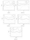
Table 3 lists the minimum, average, maximum, and thickness standard deviations of the thickness of the five test models. Figure 6 shows the thickness distribution of the five test models. It can be seen from Table 3 and Figure 6 that the thickness variation rules of the five test models are similar, it appears that the inner side of the toroidal shell is thicker than the outer side, which is consistent with the research in the literature (Zhu et al. 2020aYongmei Zhu, Binbin Chen, Bo Zhao, et al., (2020a). Buckling characteristics of externally pressurised toroidal shell, Ships and Offshore Structures, 15(8): 804-814.). In the direction, the average thickness errors of five test models are -1.5%, 0.83%, 0.25%, 0.42%, and -0.08%, respectively. Due to the grinding and processing of the welds, the maximum and minimum values fluctuate to some extent, but the thickness variation of the five test models shows good consistency, reflecting the reproducibility of the manufacturing.
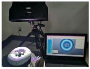
Many studies (Tu et al. 2015) have proven that imperfections of geometric shapes will affect the stability of the shell. Before conducting the hydrostatic test, the outer surface of each sample shell was accurately measured using a three-dimensional optical scanner (Open Technologies; single scan range: 150 × 115 × 150 mm; scanner pixels: 200 M; accuracy: 0.02 mm). Before scanning, the outer surface of each test model was sprayed with reflective reagents to avoid the reflection of light on the 304 stainless steel surfaces. In addition, several marker points were pasted on the surfaces of the samples to facilitate the collection of the scanned samples and complete the stitching of the pictures. The scanning process is depicted in Figure 7.
The fabrication deviations of the test models from perfect geometries were compared using GOM Inspect Suite 3D measurement data analysis software. The comparative analysis results of the five test models are presented in Figure 8.

Figure 8 shows that the five manufactured test models manufactured have small deviations from the design model. The five test models show great deviation in the reinforcement of the inner hole and the weld, and the inner and outer surface of the elbows are in good agreement with the design model. Due to the limitations of processing conditions and uncontrollable factors, the test models are slightly different from the design models but can still provide a reference for the stability test of wall reinforcement for toroidal shells with openings.
3.3 Experimentation
Analysis of the wall thickness, shape, and material parameters showed that the test models were within the range of controllable error, and the manufacturing process had good repeatability and consistency. After geometric measurements, each test model was placed in a deep-sea pressure chamber, since the buoyancy of the toroidal shell was greater than its own gravity, a net bag was used to wrap the sample with an iron block of appropriate weight in the test and ensure that the iron block was underneath. The sample was suspended and completely immersed in a clean water medium,and the loading device was a manual pressure pump. The preparation steps and procedures for the hydrostatic test were described in detail in previous reports [Zhu et al ,2020aYongmei Zhu, Binbin Chen, Bo Zhao, et al., (2020a). Buckling characteristics of externally pressurised toroidal shell, Ships and Offshore Structures, 15(8): 804-814., 2020b; Ma et al. 2018Qingli Ma. (2018). Opening reinforcement design and experimental investigation of spherical shell for deep-sea submersible. Jiangsu University of Science and Technology.a, 2018b; Zhu et al. 2019]. The pressure chamber is shown in Figure 9. The destruction of each toroidal shell with openings was accompanied by a sharp drop in pressure and models were ballasted failure sound in the chamber. The damaged toroidal shell after the experiment is shown in Figure 10, and the recorded pressure curves is shown in Figure 11.


It can be seen from Figure 10 that all test models show a local dimple. However, the failure locations of the five test models are slightly different. The failure locations of TS-0 and TS4h-16 are similar, and there are dimples on both sides of the toroidal shell. The failure locations of TS3h-16, TS3h-22 and TS4h-22 are similar, and there is dimple on one side and little change on the other side of the toroidal shell. The results show that the failure positions of the five models are symmetric with respect to the center line of the model.

Figure11 shows the variation trend of the test pressure curve. With the increase of time, the pressure curve increases first and then decreases rapidly after reaching the critical pressure. At the beginning, with the increase of pressure, the toroidal shells with openings does not change. It can be seen that the wall reinforcement design can compensate the buckling performance of toroidal shells with openings to some extent when the diameter of the opening is small. When the openings number is 3 and 4, the critical load decreases with the increase of the opening diameter. When the opening diameter is constant, the critical load of toroidal shells with three openings is greater than that of toroidal shells with four openings.
4 RESULTS AND DISCUSSION
4.1 Comparison of experimental and numerical results
To investigate the influence of different opening parameters on the buckling performance of toroidal shells with openings, finite element calculations were performed. The finite element model was established according to the real geometric shape obtained by scanning. The material parameters were taken as the mean values in Table 2. Young’s modulus: E = 200.24GPa; Poisson's ratio:= 0.300; yield strength: σs =323.60MPa.
The scanning models were processed and imported into the commercial software ANSA to complete the grid generation. The higher the mesh density is, the closer the finite element calculation result is to the real value. However, if the meshes are too dense, the computing efficiency will be significantly reduced. Therefore, there is a trade-off between the accuracy of the calculation results and calculation speeds. The mesh density convergence analysis shows that the size of the mesh should not be greater than , and the size of the mesh should be less than or equal to 3 mm. As the toroidal shells have openings, a combination of quadrilateral and triangular meshes was adopted, and the meshes were divided as shown in Figure 12. After meshing was completed, it was imported into ABAQUS for finite element analysis. In theory, the toroidal shell with openings is unconstrained under external pressure. To eliminate the rigid displacement of the model without hindering the relative deformation, this study referred to the Chinese Classification Society’s constraint on the spherical shell (CCS 2013), as well as the previous study’s (Błachut 2000) recommendations for the constraint position. Our study also adopted Blachut’s suggestion of applying symmetric boundary conditions or antisymmetric boundary conditions to the analysis of symmetric structures, and setting the four-point constraint mode with 90° symmetry.
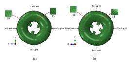
Meshing and boundary constraint mode of the numerical model: (a) three openings and (b) four openings.
In finite element analysis, linear buckling analysis and nonlinear buckling analysis were used to predict the critical buckling load of the toroidal shells. The linear buckling analysis did not consider the geometric imperfection and the material nonlinearity, so the difference between the numerical calculated result and the actual value is very large. It is necessary to conduct nonlinear buckling analysis using the Riks analysis method (Zhu et al. 2020aYongmei Zhu, Binbin Chen, Bo Zhao, et al., (2020a). Buckling characteristics of externally pressurised toroidal shell, Ships and Offshore Structures, 15(8): 804-814., 2020b). GMNA and GMNIA were performed for nonlinear buckling analysis. In the analysis step, the initial arc length was 0.01 mm, the minimum arc length was 0.05 mm, the maximum arc length was 0.5 mm, and the total arc length iteration steps was 200. The first-order mode of linear buckling analysis was introduced into the nonlinear buckling analysis, and the geometric imperfection factor was added at the same time. According to the measurement results of shell thickness, 20% of shell thickness was used as the geometric imperfection factor in this paper. The numerical analysis results are shown in Table 4.
Experimental (P test ) and numerical (P LBA, P GMNA, P GMNIA) buckling loads of toroidal shells with openings. P test is the test value, P LBA is the linear buckling analysis value, P GMNA is the geometrically and materially nonlinear buckling analysis value, P GMNIA is the geometrically and materially nonlinear analysis value with imperfections.S3 are triangular elements,S4 are quadrilateral elements.
Table 4 shows the numerical buckling load of the scanning model and test results. The critical buckling load corresponds to the pressure at the peak point of the equilibrium path curve. It can be seen from Table 4 that, when the number of openings is constant, the critical buckling load decreases with the increase of the opening diameter. When the opening diameter is constant, the critical buckling load of toroidal shells with three openings is greater than that of toroidal shells with four openings. By comparing the numerical and experimental results of the five test models, GMNIA analysis results are the closest to the experimental value, with a maximum difference of 8.7% (in the model TS4h-16), while LBA and GMNIA analysis results are significantly different from the experimental results, with a maximum difference of 57.6% (in the model TS4h-22). The calculated results based on GMNIA analysis method are in good agreement with the experimental results. The equilibrium paths of five toroidal shell scanning models were very similar. The curve and buckling and post-buckling instability modes of TS4h-16 are shown in Figure 13.
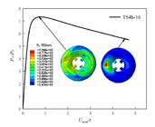
Equilibrium path, critical buckling mode, and post-buckling mode for TS4h-16, Pcr/P0 is the ratio of the applied external load to the initial load (P0 = 1 MPa), Umax/t is the ratio of the maximum deformation Umax to the nominal shell thickness t.
It can be seen from Figure 13 that, with the increase of deformation, the applied pressure increases monotonically at first and decreases significantly after reaching the critical value. The post-buckling modes of the five scanning models are shown in Figure 14. It can be seen from the figure that the post-buckling modes are all in the form of a local depression. Except TS4h-16, the buckling positions and failure modes of the other four scanning models are consistent with the test failure modes in Figure 10. The failure location of the TS4h-16 is that there are dimples on both sides of the toroidal shell, which may be caused by a manufacturing imperfections.

4.2 Effect of opening parameters on buckling characteristics of toroidal shell
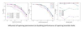
This section mainly discusses the influence of the number, size, and shape of openings on the buckling characteristics of toroidal shells. The equal area was adopted to design the shape of the opening, including circular and oval shapes. The design ensured that. According to the experimental and numerical results in Section 4.1, the GMNIA method was used to predict the buckling characteristics of the toroidal shell with openings more accurately. In this section, the number of openings was 0, 1, 2, 3, 4, 5, the diameter of the openings was 10, 16, 22, 32, and 40, and the shapes of the openings were circular and oval, respectively. A total of 51 finite element models were established. The analysis method is described in Section 4.1, and the numerical analysis results are shown in Table 5.
Figure 15 shows the effect of different opening shapes on the buckling performance of toroidal shells with openings. Under the conditions of the same area and number of openings, the critical buckling load of toroidal shells with circular openings is at least 2% higher than that of toroidal shells with oval openings. Therefore, in consideration of practical engineering applications and machining, circular openings should be given priority.
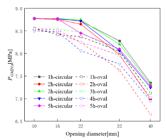
Effect of opening shape on buckling load of toroidal shells, under 1-5 holes and circular and oval shapes.
The effect of different opening sizes on the buckling performance of the toroidal shell with openings is presented in Figure 16. When the number of openings is constant, the critical buckling load of the toroidal shell decreases with the increase of opening diameter. The decreasing trend is very significant when d > 22mm (). For the toroidal shell with large openings, the effect of the wall reinforcement is not ideal, so an improved reinforcement method should be explored to improve the buckling performance of the toroidal shell ().
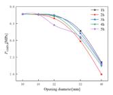
Effect of opening diameter on buckling load of toroidal shells, under 1-5 holes and circular shapes.
The effect of different numbers of openings on the buckling performance of the toroidal shell with openings is shown in Figure 17. When d > 22mm (),the opening diameter is constant, the number of openings also has a greater influence on the buckling performance of the toroidal shell. When the number of openings is odd (n=1, 3, 5), the buckling performance of toroidal shell is better than that of even number of openings (n = 2, 4). In the case of multiple openings, the buckling performance of toroidal shell with openings is the worst when n = 2. When n = 3, the toroidal shells with openings have the optimal buckling performance. This is because the buckling instability of the toroidal shell presents a rotational symmetric mode. When n = 2, the positions of the opening are selected on the symmetry axis of the toroidal shell, so buckling instability is likely to occur from the position of the symmetry axis. When n = 3, the three openings of the toroidal shell show the position relation of a triangle, demonstrating its stable performance. Therefore, in practical engineering applications, an odd number of toroidal shell openings is preferred to provide better buckling performance.

5 CONCLUSIONS
In this paper, the design of toroidal shells with openings with wall reinforcement was studied, and the influence of openings on the buckling characteristics of toroidal shells was analyzed through numerical and experimental methods. The main conclusions are as follows:
-
(1) For toroidal shells with small openings (), the performance of the wall reinforcement toroidal shell with an opening could maintain good consistency with that of the complete toroidal shell in every aspect, and the mechanical properties of the complete toroidal shell were retained. This proved the feasibility of reinforcing the toroidal shells with openings by wall reinforcement.
-
(2) After the material parameters, real profile and thickness parameters of the test models were obtained, and the critical buckling pressure of the toroidal shell with openings was determined through numerical analysis with LBA, GMNA, and GMNIA. The numerical analysis results obtained by the GMNIA were in good agreement with the test results, which also showed that the method of introducing equivalent geometric imperfection was effective and feasible.
-
(3) The opening parameters have a certain influence on the buckling characteristics of the toroidal shell with openings. With the increase of the opening diameter, the buckling load of the toroidal shell tended to decrease rapidly. When the opening diameter was constant, the buckling performances of the toroidal shell with n = 1, 3 and 5 were better than those with n = 2 and 4. When n = 2, the buckling performance was the worst.
-
(4) The effect of circular and oval openings on the buckling characteristics of toroidal shells was studied. The results showed that when the shape of the opening was circular or oval, the influence of opening parameters on the buckling characteristics of the toroidal shell were in good agreement. However, the buckling load of the toroidal shell with circular openings was at least 2% higher than that of the toroidal shell with oval openings. Considering the actual processing conditions, it was also more economical and convenient to choose the circular opening.
ACKNOWLEDGEMENTS
This work was supported by the National Natural Science Foundation of China [grant number 52071160], the Natural Science Foundation of the Jiangsu Higher Education Institutions of China [grant number 19KJA530002], and the Postgraduate Research & Practice Innovation Program of Jiangsu Province [grant number SJCX20-1446].
Reference
- Błachut, J. and Jaiswal, O.R., (2000). On buckling of toroidal shells under external pressure, Computers and Structures, 77 233-251.
- China Classification Society. (2013). Rules for the classification and construction of diving systems and submersibles. Chinese.
- Christoforos A. Dimopoulos, Charis J. Gantes. (2015). Numerical methods for the design of cylindrical steel shells with unreinforced or reinforced cutouts. Thin-Walled Structures 96:11-28.
- D. Bushnell, (1967). Symmetric and nonsymmetric buckling of finitely deformed eccentrically stiffened shells of revolution, AIAAJ. 5:1455-1462.
- Emanuele Brunesi and Roberto Nascimbene. Effects of structural openings on the buckling strength of cylindrical shells. Advances in Structural Engineering 2018, 21(16) 2466-2482.
- EN 1993-1-6:2007 (2007).Eurocode 3: design of steel structures- part 1-6: strength and stability of shell structures (Brussels: CEN, 2007).
- Flügge W, Sobel LH., (1965). Stability of shells of revolution: general theory and application to the torus. Lockheed Missiles Space Co Rep. 12:65-75.
- Flügge W., Sobel LH, (1967). Stability of toroidal shells under uniform external pressure. AIAA J. 5:425 -431.
- G.D. Galletly, D.A. Galletly, (1996). Buckling of complex toroidal shell structures, Thin- walled Struct. 26: 195-212.
- G.D. Galletly, J. Blachut, (1995). Stability of complete circular and non-circular toroidal shells, Proc. Inst. Mech. Eng. 209: 245-255.
- Guang Zou, Xingning Peng, Qinghai Du, (2012). Theoretical solution and essential research of the ring-stiffened toroidal Shell, J. Ship Mech. 16(1-2): 83-92 (In Chinese).
- [ISO] International Organization for Standardization. (2009). ISO 6892-1: metallic materials-tensile testing-Part1: method of test at room temperature. Geneva: ISO.
- J. Blachut, (2003). Collapse tests on externally pressurized toroids, J. Press. Vessel Technol. 125: 91-96.
- Jordan PF., (1973). Buckling of toroidal shells under hydrostatic pressure. AIAA J. 11:1439-1441.
- Jullien JF and Limam A (1998) Effects of openings of the buckling of cylindrical shells subjected to axial compression. Thin-Walled Structures 31(1-3): 187-202.
- O. Maching, (1963). Uber die Stabilität von Torus förmigen Schalen, Techn. Mitt. Krupp 21:105-112.
- P. f Jordan, (2012). Buckling of toroidal shells under hydrostatic pressure, AIAA J. 11:1439-1441.
- Q.L. Ma, Y.M. Zhu, W.W. Liang, et al. (2018) Buckling and strength of an externally pressurized spherical shell with reinforced opening. International Journal of Pressure Vessels and Piping, 165: 11-19.
- Qinghai Du, Weicheng Cui, Bowen Zhang. (2015). Buckling characteristics of a circular toroidal shell with stiffened ribs, Ocean Eng.
- Qinghai Du, Weicheng Cui, Zhengquan Wan, (2010). Nonlinear finite elementanalysis of a toroidal shell with ring-stiffened ribs, in: Proceedings of the ASME 2010 29th International Conference on Ocean, Offshore and Arctic Engineering, Shanghai, p 6.
- Qinghai Du, Zhengquan Wan, Weicheng Cui, (2009). A study on structural characteristics of the ring-stiffened circular toroidal shells, in: Proceedings of the 2nd International Conference on Marine Structures-Analysis and Design of Marine Structures, pp. 77-81.
- Qingli Ma. (2018). Opening reinforcement design and experimental investigation of spherical shell for deep-sea submersible. Jiangsu University of Science and Technology.
- R.A. Clark, (1950). On the theory of thin-walled toroidal shells, J. Math. Phys. 29, P146.
- Ross, C.T. F, (2006). A conceptual design of an underwater vehicle. Ocean Eng.33, 2087-2104.
- Ross, C.T.F, (2005). A conceptual design of an underwater missile launcher. Ocean Eng. 32, 85-99.
- [SAC]. (2010) Standardization Administration of the People’s Republic of China. GB/T 228.1: metallic materials - tensile testing - Part 1: method of test at room temperature. Beijing: SAC.
- S.T. Tu, X. Chen, Y. Zhu, et al. (2015). Buckling analysis of thin walled cylinder with combination of large and small stiffening rings under external pressure. Procedia Engineering, 130(12): 364-373.
- Tohid Ghanbari Ghazijahani, Hui Jiao, Damien Holloway. (2015). Structural behavior of shells with different cutouts under compression: An experimental study. Journal of Constructional Steel Research 105: 129-137.
- V.V. Novozhilov, (1951).Theory of Thin Shells, National Union Press of ship building industry, Leningrad.
- Wang A, Ren W., (1990). Progressive solution of buckling of toroidal shell. Chin J Mech. 22:35-44.
- Wang A, Zhang W., (1990). Post-buckling solution of a toroidal shell. Chin Sci. 5:485-494.
- Wang A., (1999). Buckling of a thin toroidal shell with a semi-circular cross section. J Appl Mech. 3:79-87.
- Wei Zhang, (1944). Der spannungszustand in kreisringschale und ähnlichen Schalen mit Scheitelkreisringen unter drehsymmetrischer Belastung, Arbeit zur Er-langung des Grades eines Doctor-Ingenieurs der Technichen Hochschule, Berlin.
- Yongmei Zhu,Yuewen Zhang, Xilu Zhao et al., (2019). Elastic-plastic buckling of externally pressurized hemispherical heads. Ships and Offshore Structures, 14(8): 829-838.
- Yongmei Zhu, Binbin Chen, Bo Zhao, et al., (2020a). Buckling characteristics of externally pressurised toroidal shell, Ships and Offshore Structures, 15(8): 804-814.
- Yongmei Zhu, Bo Zhao, Binbin Chen et al. (2020b). Buckling of externally pressurized toroidal shell with stiffened ribs, Journal of Pressure Vessel Technology-Transactions of the ASME, 142:061301-1.
Notation
In this paper, subscripts are used to identify quantities pertinent to a specific toroidal shell with openings.
- R - Distance from the center of the circle to the rotating axis
- r - Radius of the mid-section circle
- φ - Normal axis of the rotating axis and the cross-section
- θ -Angle of rotation of the section circle along the ring direction
- t -Thickness of the shell
- t 0 - Wall thickness
- d - The diameter of the hatch
- D - Actual hole diameter
- h 1 - Height of the lower part of the wall
- h 2 -Height of the upper part of the wall
- E - Elastic modulus
- - Poisson's ratio
- - Percentage of opening
- a - Major axis radius of the oval
- b - Minor axis radius of the oval
- n - The number of openings
- LBA -Linear buckling analysis
- GMNA - Geometrically and materially nonlinear analysis
- GMINA - Geometrically and materially nonlinear analysis with imperfections
Edited by
Editor:
Publication Dates
-
Publication in this collection
13 May 2021 -
Date of issue
2021
History
-
Received
03 Mar 2021 -
Reviewed
16 Mar 2021 -
Accepted
17 Apr 2021 -
Published
20 Apr 2021


