Effect of Nitriding on Mechanical Properties and Sulfide Stress Corrosion Resistance of Forged Supermartensitic Stainless Steel UNS S41426
Abstract
Supermartensitic stainless steels (SMSS) are corrosion resistant alloys used as casing and tubulars in the oil and gas prodution. In this application, mandrels for gas or chemical products injection in the wheel are composed of forged and hot rolled seamless tubes. SMSSs used as tubulars are subjected to sulfide stress corrosion cracking (SSC) in sour services with H2S and high salinity. Nitriding is a thermochemical treatment used to increase hardness and wear resistance of steels. This surface treatment can be used to improve the performance of SMSSs. In this work a forged SMSS grade UNS S41426 steel was plasma nitrided at 350ºC, 400ºC and 570ºC for 5 h, using gas mixture of 75%H2 and 25%N2. The effects of the microstructure were evaluated by X-ray diffraction and scanning electron microscopy. The effects on mechanical properties were evaluated by microhardness and tensile tests, while the susceptibility to SSC was evaluated by slow strain rate testing (SSRT). The average microhardness measured in the surface was 308 HV0.05 in the as received steel, and increased to 341 HV0.05, 441 HV0.05 and 1277 HV0.05 with nitriding at 350oC, 400oC and 570oC, respectively. The results were compared to specimens of SMSS not subjected to nitriding treatment.
Keywords:
Supermartensitic Stainless Steel; Nitriding
1. Introduction
Supermartensitic stainless steels (SSMS) are a relatively new sub-family of martensitic stainless steels modified to obtain higher corrosion resistance and improved mechanical properties and weldability1-3. These materials are used as tubulars and casing for oil and gas production in deep water weels3,4, composing a system called OCTG (oil country tubular goods). SMSSs were used in pipeline for oil and gas transportation5,6. As tubulars, in the collum of oil production, the internal walls are subjected to the abrasive wear caused by sand. Other concern in OCTG applications is the sulfide stress cracking (SSC) 2,7, which is defined as cracking of metal involving corrosion and tensile stress (residual and/or applied) in the presence of H2S and H2O8.
Surface treatments like nitriding and carbonitriding are applied to martensitic stainless steels with the aim of increase hardness and wear resistance8-12. These thermochemical treatments may also create a desirable compressive stress state which enhances fatigue life13,14 and SSC nucleation.
Li and Bell11 studied the effects of plasma nitriding of an AISI 410 steel (12.20%C, 0.15%C, 0.27%Ni, 0.33%Si, 0.44%Mn) at 420oC, 460oC and 500oC with 25% N2+75% H2 gas, for 20h. The nitrided layer was found to increase with the processing temperature, while the surface hardness obtained were 1210 HV0.1, 1204 HV0.1 and 1113 HV0.1 with nitridings at 420oC, 460oC and 500oC, respectively. The authors also found that the plasma nitriding improved the corrosion resistance of the AISI 410 stainless steel in 1% HCl and in 3.5% NaCl aqueous solution even when the processing temperature was high (500oC).
Corengia et al.12 also studied the nitriding of AISI 410 steel with 25% N2+75% H2 gas, for 20h. The corrosion resistance of specimens nitrided at 400oC and 500oC were severely decreased due to the formation of CrN, while nitriding at 350oC can avoid the formation of this phase11,12.
Dalibón et al.9 performed short duration (2h) plasma nitriding of AISI 420 stainless steel with 50%N2 and 50%H2 mixture at 420oC and 440oC. The authors avoided the formation of chromium nitrides in the nitrided layer using low temperatures and short duration processing.
Fernandes et al.15 studied the plasma nitriding and carbonitriding of a SMSS grade UNS S41525 (microalloyed with N) by the DC method. The as quenched steel was nitrided at 400oC, 450oC and 500oC for 5h in an atmosphere of 80%H2+20%N2 with working pressure of 500 Pa. The study revealed that the amounts of ε-nitride and expanded phases decreased, and the γ'-nitride and chromium nitride (CrN) increased with the increase of temperature. The pitting corrosion resistance decreased with the increase of nitriding temperature, and this was related to the increase of CrN formation in the nitrided layer.
Kurelo et al.16,17 performed plasma ion implantation in Ti-alloyed SMSS UNS S41426. The gas mixture chosed by these authors was composed by 60%H2+40%N2. The samples were nitrided at low temperatures, 300oC, 350oC and 400oC, for 3 hours, with DC voltage 500V, current 210 mA, and pressure of 400 Pa. The authors avoided the CrN precipitation using low processing temperatures and obtained increased wear resistance.
In the present work, we studied the effects of low and high temperature plasma ion nitriding on the SSC susceptibility of a forged Ti-alloyed supermartensitic stainless UNS S41426. Since the nitriding treatment is one of the possibilities to increase the erosion resistance of tubulars, casings and valves in the OCTG application, its effect on the SCC must be evaluated.
2. Materials and Methods
The material submitted for plasma ion nitriding in this work was an UNS S41426 from a forged piece, with chemical composition shown in Table 1. A complete microstructural and mechanical properties analysis of this material was published in18. The received steel contains tempered martensite, delta ferrite, coarse and square shaped TiN precipitates, fine Ti (C, N) carbonitrides, and 16.9% of reversed austenite. The average previous austenite grain size is 29.7 µm. The mechanical properties of the as received steel are resumed in Table 2.
Mechanical properties and microstructural parameters of the as received steel 18.σYS = yield strength (0.2%), σUTS = ultimate tensile strength, El = total elongation, CVN = Charpy impact energy (-46oC).
Two types of specimens were cut and machined for plasma nitriding, a plate one with dimensions 20 x 15 x 4 mm3, and tensile specimens with gauge length 26 mm and diameter 3.8 mm. Both groups of specimens were nitrided in the same processing conditions. The flat specimens were used for characterization of the nitrided layer. The tensile specimens were destinated to slow strain rate testing (SSRT) after nitriding.
The plate specimens were ground and polished with 0.3 µm alumina before the plasma nitriding process. It was not possible to polish the tensile specimens, due to their cylindrical geometry. Before the nitriding process, the plate and the tensile specimens were subjected to ultrasonic cleaning and immersed in alcohol for 10 minutes to eliminate any residual dirt. After preparation and drying, the specimens were positioned in the plasma reactor, ensuring no contact between them to avoid interference during the nitriding process.
The plasma ion nitriding was conducted in a reactor consisting of a cylindrical steel vacuum chamber connected to a vacuum pump, which ensured the evacuation of the chamber. The flow rates of the gases introduced to the chamber (argon, nitrogen and hydrogen) were regulated using a set of three flow meters. Temperature measurements were performed using a type K thermocouple positioned at the base of the specimen holder. The specimens were placed on an insulating disk made of aluminium oxide (Al2O3).
A pre-treatment was performed using a gas mixture of 50% argon and 50% hydrogen at 350°C for 1 hour. Subsequently, the gas flow was adjusted, and a gas mixture of 75% H2 and 25% N2 was used for nitriding the samples and specimens. The treatment was carried out for 5 hours at three distinct temperatures: 350°C, 400°C, and 570°C. Cooling was gradual and occurred inside the plasma reactor. The nitrided samples were named N350, N400 and N570, and they were compared with the as received (AR) SMSS.
After nitriding, the flat samples were used for microhardness testing and for determining the phases and residual stresses present in the steel by X-ray diffraction.
For scanning electron microscopy (SEM) the nitrided specimens were cross-sectioned and mounted in bakelite, at 180°C for 3.5 minutes. The specimens were ground with abrasive papers with grain sizes ranging from 200 to 1200 mesh, followed by polishing with diamond pastes with 6 µm, 3 µm and 1 µm particle sizes. Then, the samples were etched with Villela’s reagent (95 ml ethanol, 5 ml HCl, 1g picric acid) and the microstructure of the nitride layer was observed in a FEG/SEM microscope JEOL model JSM 7100F.
Vickers microhardness of N350, N400 and N570 samples were measured with a microhardness tester Innovatest Falcon 40 with a 50X objective lens and load of 10 gf. Ten tests per condition were performed.
X-ray diffraction (XRD) was conducted using a Rigaku MiniFlex II X-ray diffractometer with a CuKα radiation source (wavelength λ = 1.5406 Å). Measurements were performed in N350, N400, N570 and AR specimens, within a scanning angle range of 25° to 100°, with 0.5° steps at a speed of 2°/minute, and voltage and current settings of 30 kV and 15 mA, respectively.
Residual stress in the surface of N350, N400 and N570 plate specimens were measured by X-ray diffraction using the sin2ψ method with the XStress3000 residual stress analyzer, employing ψ angles of 0°, 20.7°, 30°, 37.7°, and 45°, with an exposure time of 5 seconds per point, at a voltage of 30 kV and current of 6.7 mA.
The nitride cylindrical specimens were used for tensile testing at low strain rates, in a CORTEST machine. The tests were conducted at room temperature with a constant velocity of 0.001566 mm/min and an initial strain rate of 1.0 x 10⁻⁶ s-1. The specimens were tested in two solutions, both with 200 g/L NaCl. A flux of 3.45%H2S/96.55%CO2 gas was used, meaning a H2S partial pressure of 0.5 psi. The two solutions differ in the pH level, which was adjusted with NaHCO3 and C2H3NaO2 additions. In solution 1 the pH was 5.0 ± 0.1 and in solution 2 the pH was 5.5 ± 0.1.
SSRT results in the test solution are compared with tests in inert atmosphere (air, in the case of stainless steels)19. In this work, the tests in the aggressive solution and in air were performed in duplicate. The parameters adopted to evaluate the susceptibility to SSC are defined below:
-
, the ratio between total elongation (El.) in the test solution containing H2S and in air (inert);
-
, the ratio between reduction in area (RA) in the test solution and in air;
-
, the ratio between the area of the nominal stress (σ) versus nominal strain (ε) curve in the test solution and in air.
After the SSRT the fracture surfaces were cleaned, preserved and observed in the SEM.
3. Results and Discussion
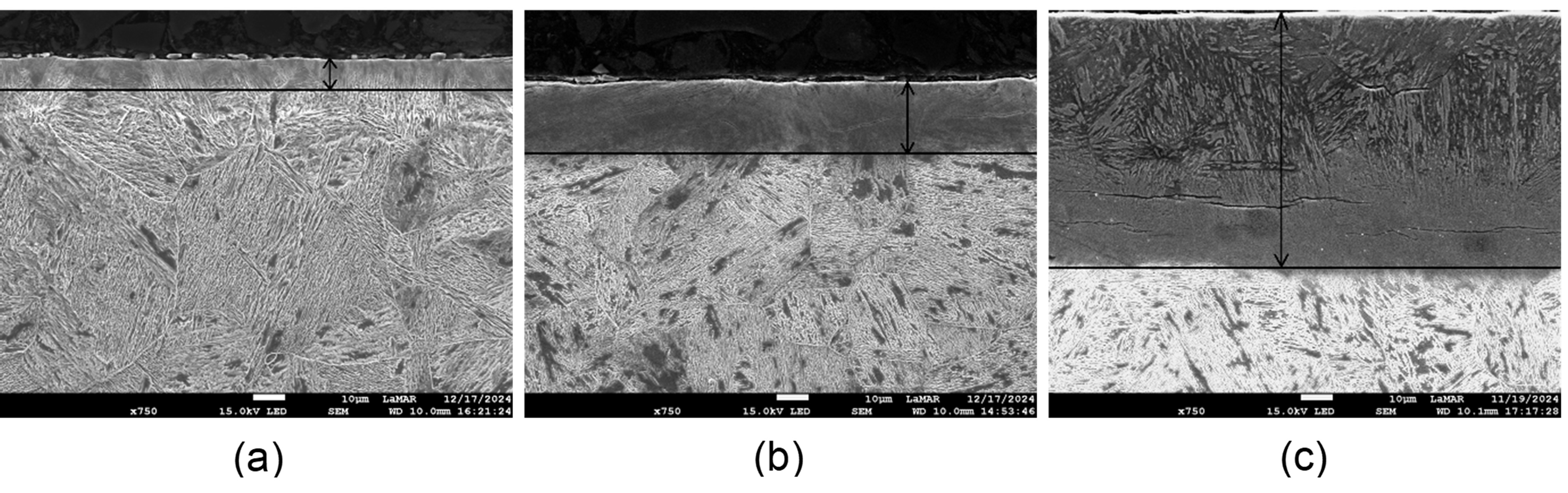
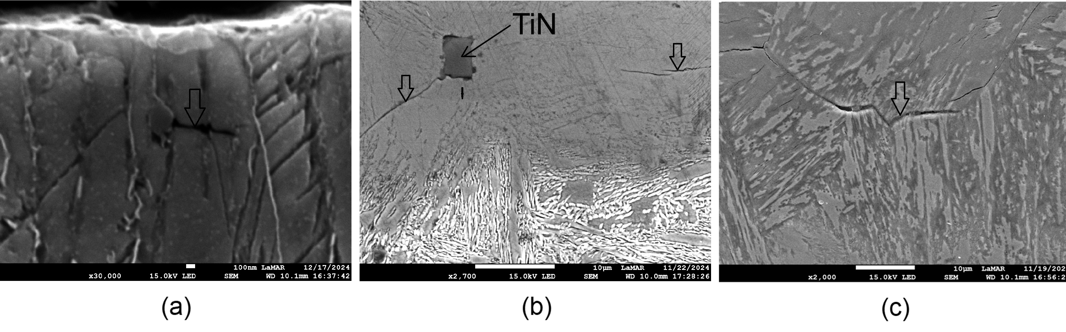
Figure 1 presents the SEM images of the nitride layers. The average thicknesses of the nitride layers are presented in Table 3, and are found to increase with processing temperatures, as observed in previous works9,11,12. Microcracks were observed in the nitride layer of N350, N400 and N570 as shown with detail in Figure 2(a-c). In a qualitative analysis, the number of microcracks increases with the processing temperature. In Figure 2(b) a crack in the N400 specimen is found to grow from an endogenous TiN particle.
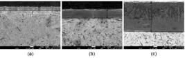
Nitrided samples (a) N350; (b) N400; (c) N570. The limits of the nitride layers are delimitated.
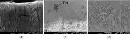
Table 3 also shows the microhardness and the residual stresses measured in the surface of N350, N400 and N570. The microhardness was higher in the specimen nitrided at 400oC followed by that nitrided at 570oC. The residual stresses were all compressive, with the magnitude increasing with the nitriding temperature. This result confirms the ability of nitriding to produce compressive residual stresses in the surface, which can be beneficial for fatigue and sulfide stress corrosion cracking (SCCC) resistance. However, specimen nitrided at 570oC was also the one with higher density of microcracks, which is surely detrimental to the performance of SMSS in aggressive media.
The nitrides formed in the process cause compressive residual stresses in the nitriding surface. It occurs because the nitrides are more voluminous than the martensitic matrix20. The increase of nitrides precipitation enhances the magnitude of compressive residual stress, but also increases the cracks generation in the nitrided layer20. In agreement, Hwang et al21 demonstrated that residual stress can be the dominant factor in the creation of internal cracks.
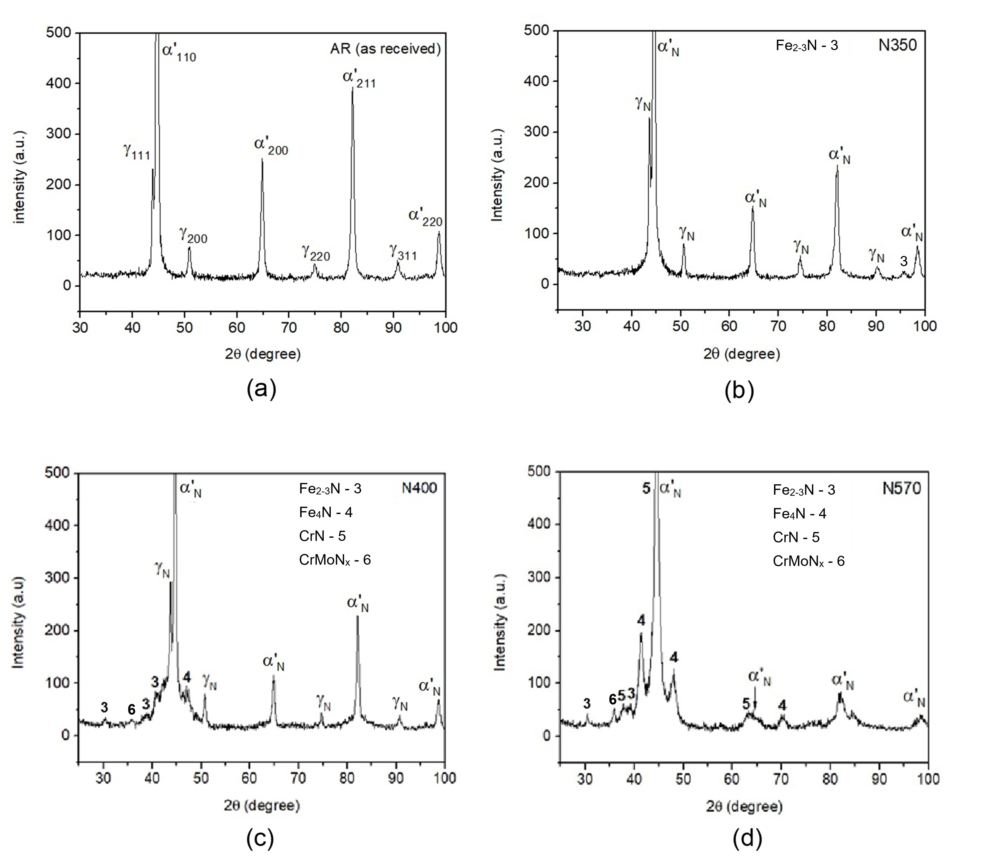
Figures 3(a-d) show the XRD diffractograms of AR, N350, N400 and N570 specimens. For peak identification the JCPDS PDF cards of austenite (γ) (33-397), martensite (α’) (34-396), CrN (76-2494), Fe4N (86-0231), CrMoNx (10-0197), Fe2-3 (49-1664, 72-2126 and 73-2103) were used. The as received (AR) material contains martensite (α’) and reverse austenite (γ) formed during the heat treatment of SMSS, as reported elsewhere18. The diffractogram of the steel nitrided at 350oC (N350, Figure 3(b)) shows the phases α’N (martensite expanded) and γN (austenite expanded). with d spacing slightly increased due to the nitrogen dissolved in interstitial sites22. As will be shown, this effect is more pronounced in the austenite phases than in martensite, due to the higher solubility of nitrogen in fcc austenite. The hardening observed in the nitride layer of sample N350 is mainly due to the interstitial solid solution strengthening.
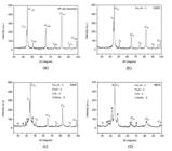
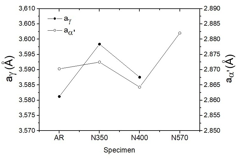
The X-ray diffractogram of specimen nitrided at 400oC (N400, Figure 3(c)) showed the expanded phases α’N and γN and peaks characteristics of iron nitrides Fe4N and Fe2-3N. These nitrides formed with nitrogen not dissolved in martensite or austenite, make the hardness achieve the maximum value (1490 HV0.010). Figure 4 shows the lattice parameters of austenite (γ) and martensite (α’) calculated from the d spacing of γ111, γ200 and γ220 reflections for austenite and α’111, α’200 and α’220 for martensite, as function of the nitriding temperature. The increase of lattice parameter of austenite and martensite from AR to N350 samples indicates that the nitriding at 350oC caused the lattice expansion due to N in solid solution, as commented before. When the nitriding temperature is raised to 400oC, Fe2-3N and Fe4N nitrides precipitate and the lattice parameters decrease, suggesting that at this temperature the nitrogen is rather used to form precipitates.
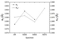
The diffractogram of specimen nitrided at 570oC (N570, Figure 3(d)) showed two important changes in relation to the specimen N400, specifically the appearance of CrN reflections, and the disappearance of the γ’N phase. The iron nitrides reflections (Fe4N and Fe2-3N) are present and with high intensity, denoting that the increase of the processing temperature also provoked the increase of these nitrides. It justifies the maximum compressive residual stress measured and the observation of more cracks in the nitride layer. At the same time, the lattice parameter of the α’N phase was increased (Figure 4), indicating that this phase dissolves more nitrogen in the N570 specimen.
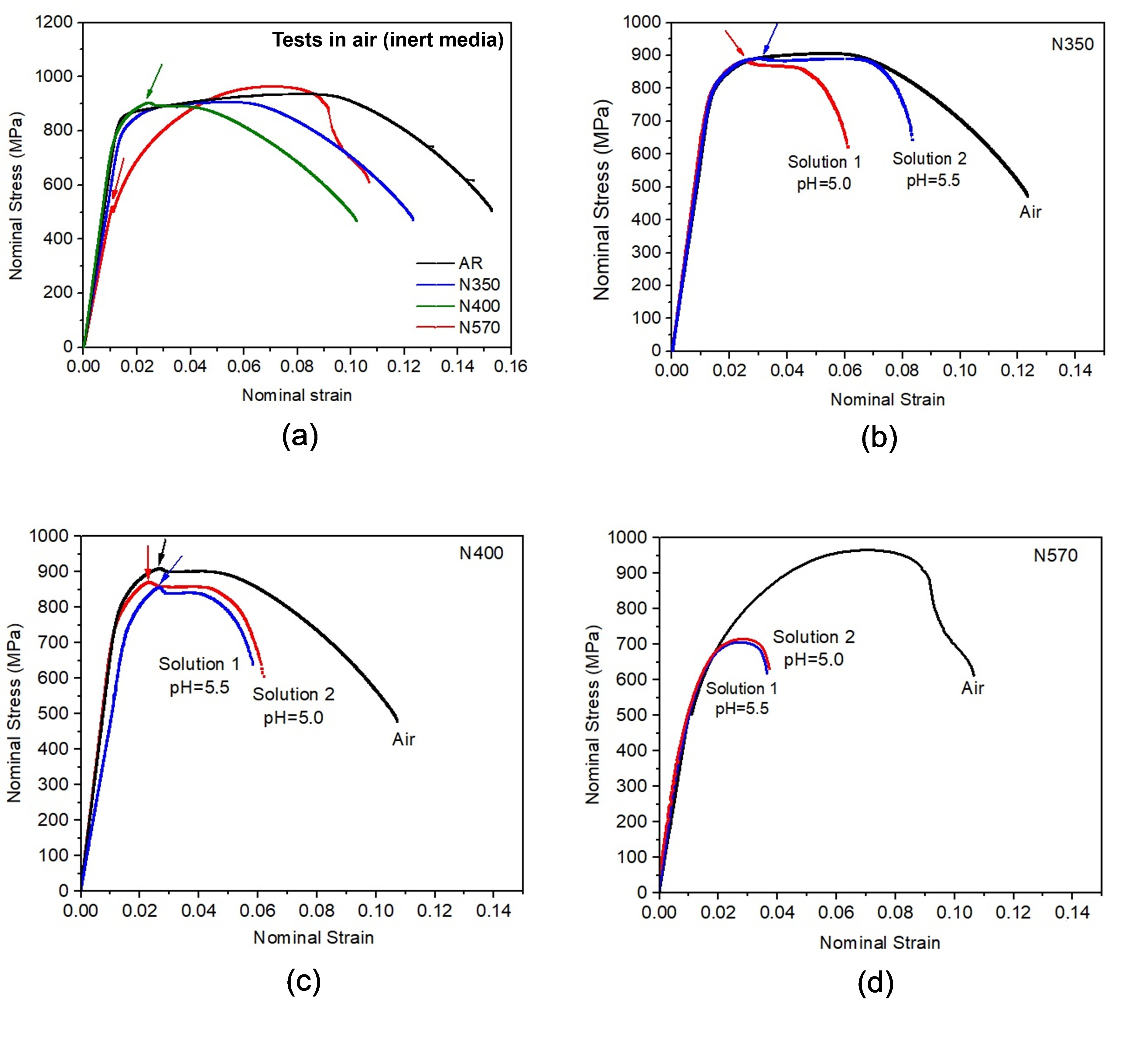
The SSRT curves are shown in Figure 5(a-d). Figure 5(a) compares the tensile behavior of samples tested in air (inert media for SMSSs). As can be seen, the nitridng process caused the decrease of total and uniform elongation in samples N350 and N400, when compared to the AR material. Specimen N570 showed a completely different curve, in which the yield strength (σYS) is low (520 MPa) but the material undergoes a considerably strain hardening, reaching an ultimate strength (σUTS) of 965 MPa. The uniform elongation of this sample was higher than found in N350 and N400. The arrows in the curves of N400 and N570 (Figure 5(a)) were inserted to indicate a point of discontinuity in the curves. Figure 5(b) shows the comparison of SSRT curves of N350 in the two test solutions and in air. The points of discontinuity which are not present in the test in air for N350 appear in the tests in the aggressive solutions. The comparison for the N400 specimens is shown in Figure 5(c), where the three curves present the discontinuity point. These points, where the tensile curves present a drop, or a discontinuity, are associated to the failure of the nitride layer. It has already happened in specimens N400 and N570 tested in air, occurring in the end of the elastic regime for N570. This sample presents a thicker nitride layer, brittle and with many microcracks. In tests conducted in the aggressive media, all N350 and N400 specimens showed this behavior, due to the action of salinity and hydrogen.
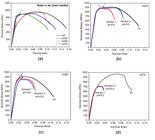
Sulfide stress corrosion evaluation by SSRT: a) all conditions in air (inert); b) N350 specimens; (c) N400 specimens; (d) N570 specimens.
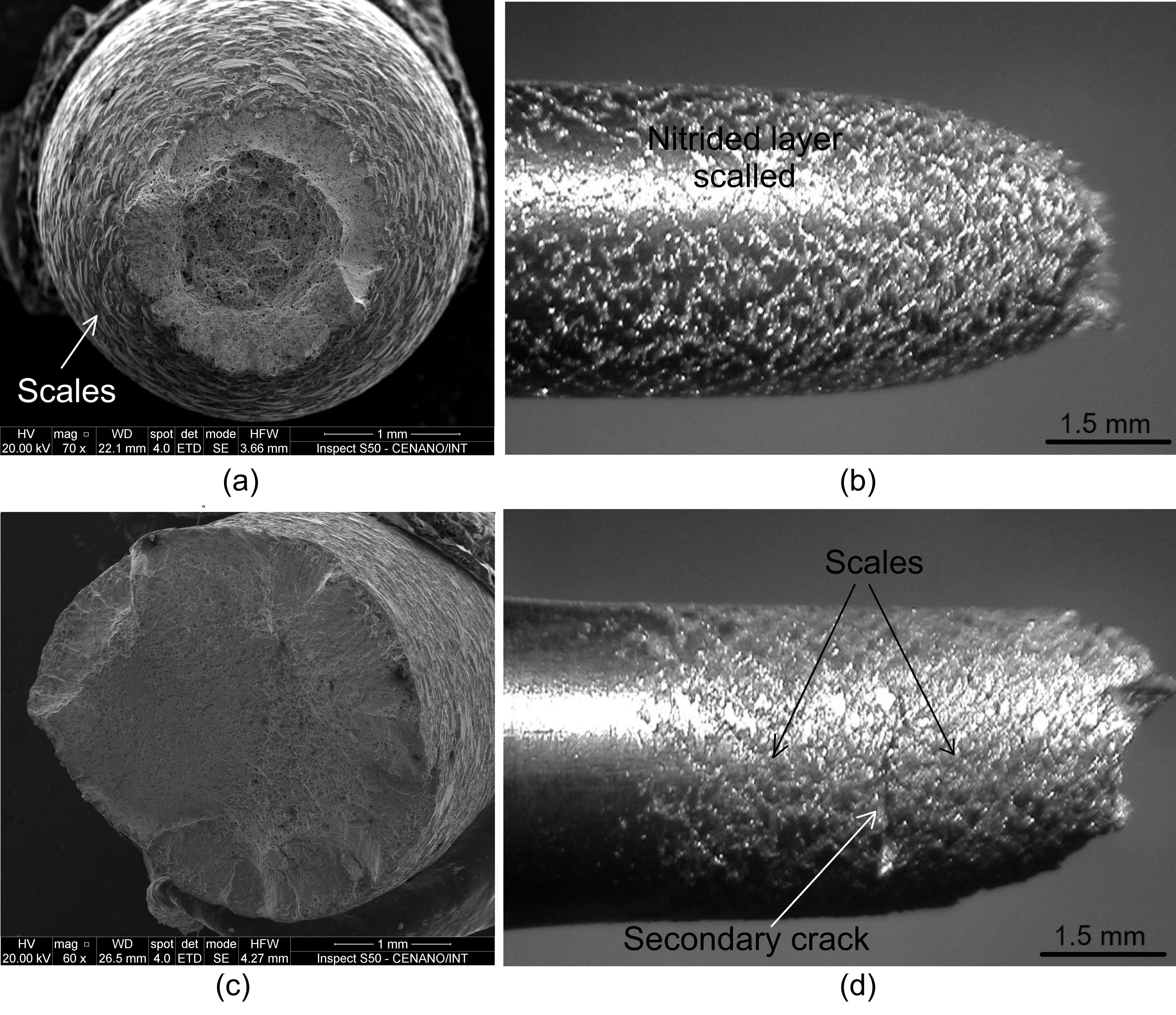
Although the point of discontinuity is not observed in the tensile curve of specimen N350, it is possible to see the nitride layer scaled near the fracture surface, as shown in Figures 6(a-b). Figures 6(c-d) show the fracture surface and the nitride layer of N350 tested in solution 1 (pH=5.0). The fracture is brittle and contains secondary cracks. The profile of the specimen shows the scaling of the thin nitride layer in the region close to the fracture, while a less stressed region far from the fracture does not present scales of the nitrided layer.
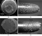
Nitride Layer Cracked in the N350 Specimen Tested in (a-b) air and (c-d) solution 1 (pH=5.0).
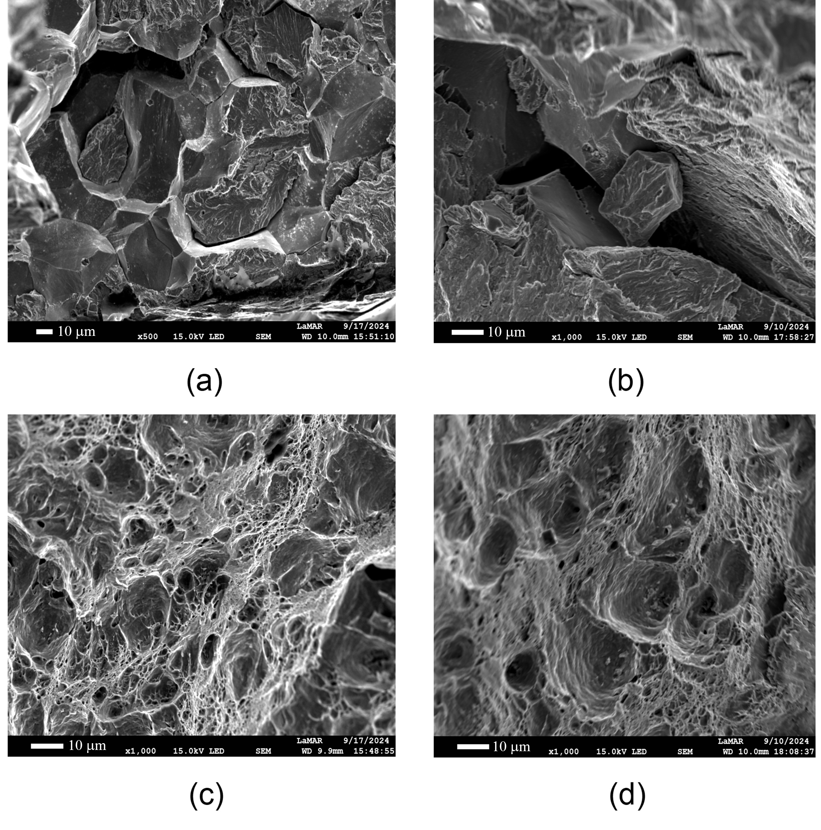
Specimens of N400 tested in solutions 1 (Figures 7(a-c)) and 2 (Figures 7(b-d)) showed brittle features, a mix of cleavage and intergranular cracking, near the edges, as shown in Figures 7(a-b) In the core of embrittled specimens a region of dimples is frequently observed (Figures 7(c-d)), indicating that less hydrogen achieved the central part of the specimens during the SSRT tests.
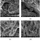
Fracture Surfaces of Specimens N400 at: (a) solution 1 - edge; (b) solution 2 - edge; (c) solution 1 - center; (d) solution 2 – center.
Comparing the specimens N350 tested in air, with those tested in test solution 1 (pH=5.0) and solution 2 (pH=5.5), it is observed a slight increase of the embrittlement effect with the decrease of pH. The comparison for specimens N400 reveals no significant difference between the two test solutions and the average indexes in the same level of specimens N350. However, in N570 specimens both solutions provoked severe embrittlement effects. These data are treated quantitatively in Table 4, which presents the embrittlement indexes calculated from the comparison of SSRT curves. The material nitrided at 570oC was the most susceptible to sulfide stress corrosion cracking (SSCC). It seems also evident that the thick nitride layer obtained in this high process temperature did not impair the diffusion of hydrogen, and the several microcracks in the nitride layer contributed to the SCC failure. Also, as pointed out in previous works15, the precipitation of CrN makes the material more susceptible to localized corrosion.
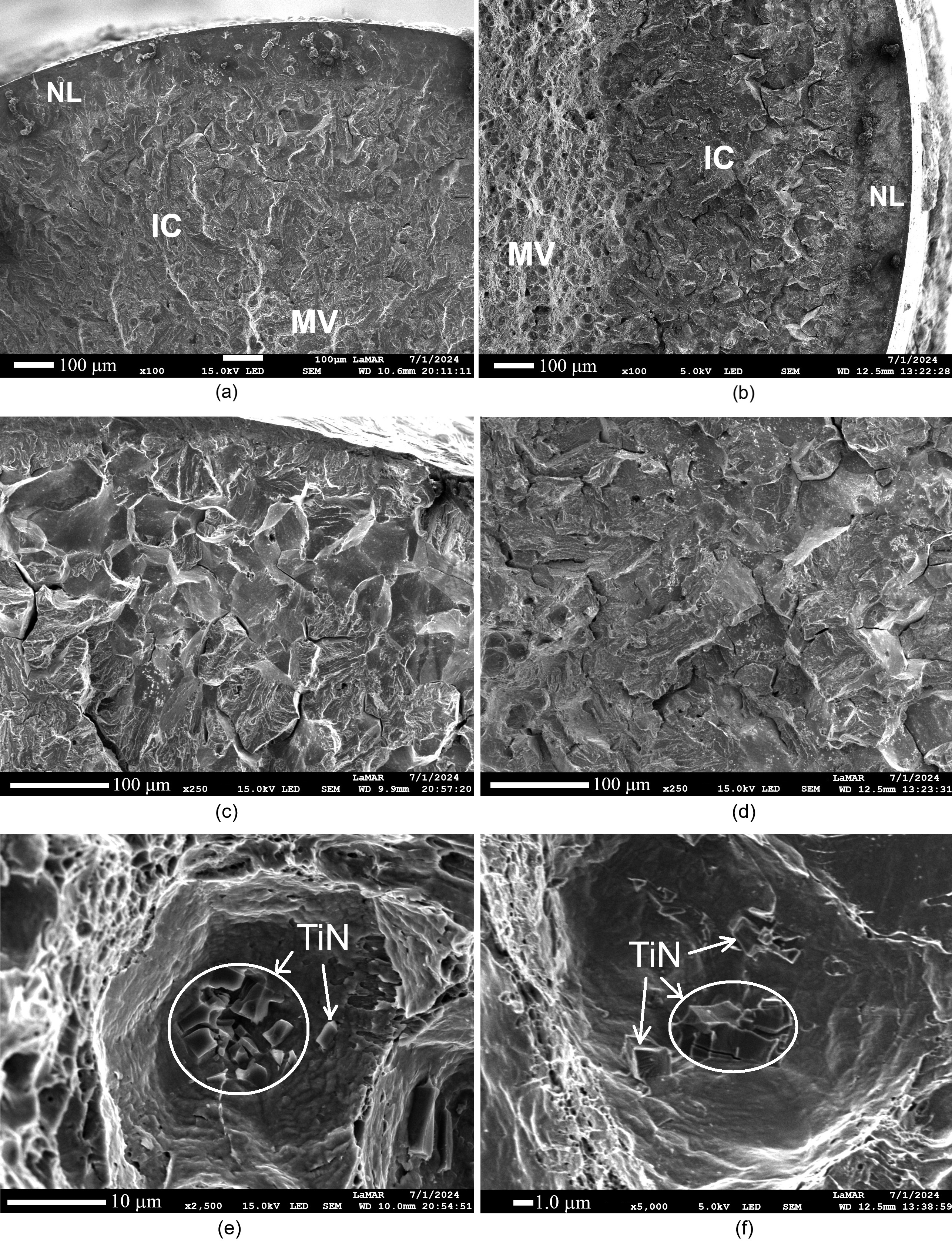
Figures 8(a-f) show the fracture surfaces of specimens N570 tested in solutions 1 and 2. These two specimens have very similar features, in agreement with their susceptibility indexes (see Table 4). In the low magnification images of both specimens (Figures 8(a-b)) three regions can be identified: the brittle nitride layer (NL) followed by an extremely brittle region of the SMSS with intergranular cracks (IC), and a central region with microvoids (MV). Figures 8(c-d) show the region of intergranular cracking, and Figures 8(e-f) are from the region with microvoids. Frequently, the dimples contain fractured TiN particles inside. These cracks in the TiN particles were caused by the hydrogen which diffused and reached this region. The H concentration in the center part of the specimen was not sufficient to provoke intergranular crack but caused the embritlement of the coarse TiN precipitates.
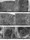
Fracture Surfaces of Specimens N570 tested with (a) Solution 1 and (b) Solution 2. (NL = nitride layer, IC=Intergranular cracking, MV=microvoids).
Lower reduction ratio of area, elongation, and toughness were observed for specimens nitrided at 570°C, indicating greater susceptibility to sulfide stress corrosion. Despite the high compressive residual stress produced in the N570 specimen the nitriding at such high temperature is not recommended to SMSSs.
4. Conclusions
The effects of plasma ion nitriding of a supermartensitic stainless steel UNS S41426 at 350oC, 400oC and 570oC for 5h, in 75%H2+25%N2 gas mixture, were studied. The samples were named N350, N400 and N570. The main conclusions are:
-
The plasma nitriding induced compressive residual stresses, which increased with the processing temperature.
-
The peak of hardness was achieved with nitriding at 400oC and the thickness of the nitride layer increased with nitriding temperature, reaching 90 µm in the N570 sample.
-
The phases encountered by X-ray diffraction were expanded martensite (α’N) and austenite (γN) in N350, γN, α’N and iron nitrides (Fe2-3N and Fe4N) in N400, and α’N, iron nitrides and chominum nitride (CrN) in N570.
-
The susceptibility to sulfide stress corrosion cracking (SSCC) was evaluated by slow strain rate testing (SSRT) with susceptibility indexes, and the material nitrided at higher temperature (N570) was found to be the most susceptible to SSCC. Specimens nitrided at 350oC (N350) and 400oC (N400) were also embrittled, but with a less extent.
5. Acknowledgements
Authors acknowledge CNPq (308244/2022-2) and FAPERJ (E-26/200.423/2023; E-26/204.777/2022).
6. References
- 1 Barbosa C, Abud I. Recent developments on martensitic stainless steels for oil and gas production. Recent Pat Corros Sci. 2013;3(1):27-38.
- 2 Taban E, Kaluc E, Ojo OO. Properties, weldability and corro sion behavior of supermartensitic stainless steels for on- and offshore applications. Mater Test. 2016;58(6):501-18.
- 3 Kimura M, Tamari T, Shimamoto K. High Cr stainless steel OCTG with high strength and superior corrosion resistance. JFE Tech Rep. 2006;7:7-13.
- 4 Shiryaev AG, Chetverikov SG, Chikalov SG, Pyshmintsev IY, Krylov PV. Production of seamless steel pipe for oil and gas extraction in challenging conditions. Steel Transl. 2018;48(11):704-11.
- 5 Miyata Y, Kimura M, Murase F. Development of martensitic seamless pipe for linepipe application. Tokyo: JFE Steel Corporation; 1998. p. 53-60. (Kawasaki Steel Technical Report; 38).
- 6 Hoffmann R, Schüller T, Mühe B, Rommerskirchen I. Experiences with supermartensitic stainless steels in the pipe production based on research work and first commercial orders. In: Supermartensitic Stainless Steels 2002; 2002 Oct 3-4; Brussels, Belgium. Proceedings. Toronto: Stainless Steel World; 2002. p. 129-34.
-
7 Ortiz Alonso CJ, Lucio-Garcia MA, Hermoso-Diaz IA, Chacon-Nava JG, Martinez Villafañe A, Gonzalez-Rodriguez JG. Detection of sulfide stress cracking in a supermartensitic stainless steel by using electrochemical noise. Int J Electrochem Sci. 2014;9(12):6717-33. http://doi.org/10.1016/S1452-3981(23)10925-4
» http://doi.org/10.1016/S1452-3981(23)10925-4 -
8 Shin D-H, Hwang H-K, Kim S-J. Effect of plasma ion nitriding on hydrogen embrittlement and wear resistance of martensitic stainless steel for hydrogen valve core of fuel cell electric vehicles. Eng Fract Mech. 2024;306:110247. http://doi.org/10.1016/j.engfracmech.2024.110247
» http://doi.org/10.1016/j.engfracmech.2024.110247 - 9 Dalibón EL, Dalke A, Biermann H, Brühl SP. Short time nitriding and nitrocarburizing of martensitic stainless steel. Surf Coat Tech. 2024;485:130931.
-
10 Mansilla C, Ocelík V, De Hosson JTM. Local residual stress measurements on nitride layers. Mater Sci Eng A. 2015;636:476-83. http://doi.org/10.1016/j.msea.2015.04.023
» http://doi.org/10.1016/j.msea.2015.04.023 - 11 Li CX, Bell T. Corrosion properties of plasma nitrided AISI 410 martensitic stainless steel in 3.5% NaCl and 1% HCl aqueous solutions. Corros Sci. 2006;48(8):2036-49.
- 12 Corengia P, Ybarra G, Moina C, Cabo A, Broitman E. Microstructure and corrosion behaviour of DC-pulsed plasma nitrided AISI 410 martensitic stainless steel. Surf Coat Tech. 2004;187(1):63-9.
-
13 Casteletti LC, Lombardi Neto A, Totten GE. Nitriding of stainless steels. Metallogr Microstruct Anal. 2014;3(6):477-508. http://doi.org/10.1007/s13632-014-0170-4
» http://doi.org/10.1007/s13632-014-0170-4 -
14 Bai Z, Wu X. Improving stress corrosion resistance and wear resistance of austenitic hot-stamping die steels via synergistic effects of shot peening and plasma nitriding. Surf Coat Tech. 2024;478:130448. http://doi.org/10.1016/j.surfcoat.2024.130448
» http://doi.org/10.1016/j.surfcoat.2024.130448 - 15 Fernandes FAP, Picone CA, Totten GE, Casteletti LC. Corrosion behavior of plasma nitrided and nitrocarburised supermartensitic stainless steel. Mater Res. 2018;21(3):e20160793.
- 16 Kurelo BCES, Souza GB, Serbena FC, Oliveira WR, Marino CEB, Taminato LA. Performance of nitrogen ion-implanted supermartensitic stainless steel in chlorine- and hydrogen-rich environments. Surf Coat Tech. 2018;351:29-41.
- 17 Kurelo BCES, Oliveira WR, Serbena FC, Souza GB. Surface mechanics and wear resistance of supermartensitic stainless steel nitrided by plasma immersion ion implantation. Surf Coat Tech. 2018;353:199-209.
- 18 Baptista IP, Pimenta AR, Heringer MAV, Perez G, Tavares SSM. Microstructure, mechanical properties, and corrosion resistance of supermartensitic steel UNS S41426: comparison between forged and hot‑rolled seamless pipe. Int. J.of Adv. Manuf Tech. 2022;123(7-8):2643-53.
- 19 ASTM: American Society for Testing and Materials. ASTM G129-21: standard Practice for slow strain rate testing to evaluate the susceptibility of metallic materials to environmentally assisted cracking. West Conshohocken: ASTM, 2021.
- 20 Jegou S, Barrallier L, Fallot G. Gaseous nitriding behaviour of 33CrMoV12-9 steel: evolution of the grain boundaries precipitation and influence on residual stress development. Surf Coat Tech. 2018;339:78-90.
- 21 Hwang BW, Suh CM, Jang HK. Effects of surface hardening and residual stress on the fatigue characteristics of nitrided SACM 645 steel. Int J Mod Phys B. 2003;17(8-9):1633-9.
- 22 Manova D, Thorwarth G, Mändl S, Neumann H, Stritzker B, Rauschenbach B. Variable lattice expansion in martensitic stainless steel after nitrogen ion implantation. Nucl Instrum Methods Phys Res B. 2006;242(1-2):285-8.
- 23 NACE International. NACE MR0175/ISO 15156-2:2003: Petroleum and natural gas industries - Materials for use in H2S-containing Environments in oil and gas production - Part 2: Cracking-resistant carbon and low alloy steels, and the use of cast irons. Houston: NACE International; 2003.