Metallurgical and Mechanical Examination of Fatigue-Induced Fracture in a Conveyor Drum Shaft
Abstract
This work investigates the fatigue failure mode of a shaft used in a conveyor system for mining applications through visual inspection, metallographic examination, fracture analysis, and mechanical testing. It was observed that a misalignment of about 5° between the shaft and the conveyor drum system promoted intensive contact with the parts. The combination of misalignment and overload was the leading cause of the localized plastic deformation, which resulted in the shaft fracture. A metallurgical examination revealed ferritic and pearlitic microstructures for an AISI 4140 grade steel. This suggested that the heat treatment on the steel was not adequate for the application. Therefore, it can be inferred that no preventive or corrective maintenance inspections were performed during the shaft's operational production period.
Keywords:
Conveyor drum shaft; fracture surface; failure analysis; metallographic inspection; mechanical properties
1. Introduction
A drum shaft is customized cylindrical component that supports and rotates a drum in various mechanical scenarios, typically within machinery such as industrial washing, industrial conveyor systems, or any equipment utilizing rotational motion to function. In pure engineering, a drum shaft is a critical metallic component that serves as the axis around which a drum rotates, allowing for the transfer of force and motion. In the case of conveyor belt pulleys, they are crucial components in mining operations, enabling the efficient movement of bulk materials over long distances1. This is why industrial equipment plays an essential role in the reliability and performance of the industry worldwide.
Appropriate material selection according to the application conditions increases the working life of the mechanical elements. The proper selection covers the face length, belt tension (i.e., conveyed load, catenary load, the take-up mechanism), shaft and outer diameter, style of the hub connection, pulley configuration, pulley face profile, type of required contact surface and performance requirements2. If this selection is conducted in haste, a conveyor drum shaft may be inadequately sized, installed, and overloaded, leading to several trouble operations, premature failure, and costly downtime. Sensitive components include the axle disk, drum shell, and the connection of different components. Nonetheless, the primary focus of attention has been drawn to the bending load of the drum shaft, which is supported by two symmetrical outer bearings3.
Thus, as an attempt to optimize the desired performance requirements of the engineering components, engineers make evaluations of load service and working conditions, by calculating the stress due to loads conditions such that the stresses get limited to values below the critical specified values for the potential failure modes of the component (i.e., yielding, buckling, fatigue, creep, and brittle fracture)4. So, the probability (and the economic consequences) of failure must be possibly lowered. Premature failure may occur due to the complexity of the working conditions of the drum shaft. For example, material deterioration, variations in shape, loading, and external operating conditions may individually result in shaft failure. The failure of rotating machinery shafts has been studied in detail by several researchers and summarized by Hou et al.5. By identifying the fracture modes (i.e., cracking and propagation) and their causes, effective measures can be put forward to improve the service life of shafts. In this sense, preventing brittle fracture is also the most critical engineering task because of the sudden and uncontrolled mode when materials fail in service6. In consequence, the potential of multi-disciplinary failure analysis assesses diverse fields of knowledge, such as design issues, mechanics, chemistry, metallurgy, non-destructive testing, and fractography for understanding the chain of events that happened before and after the failure of a metallic material7. Most fracture cases studied have found that fatigue is one of the most common failure mechanisms in shafts8. However, the fracture mechanics of metallic materials is a problem far from being solved due to the high variety of phenomena involved at the moment of their failure7. Still, its study contributes to understanding the reasons and how the risk can be diminished or avoided.
The objective of this investigation was to analyze and characterize the failure of a drum shaft, which was reported by the maintenance crew of a mining company. The investigation included visual analysis, chemical analysis of the material in the center of the shaft, hardness measurements of the central surface of the fractured region, Charpy impact testing, tensile testing, metallographic analysis using optical microscopy, scanning electron microscopy, and fractographic analysis by scanning electron microscopy. As received, the sections of the fractured piece did not have any identification regarding the type of steel used in the shaft's manufacturing. Identification details are likely retained in the company’s records. Consequently, the supplier is also not mentioned.
2. Materials and Methodology
2.1. Failure description
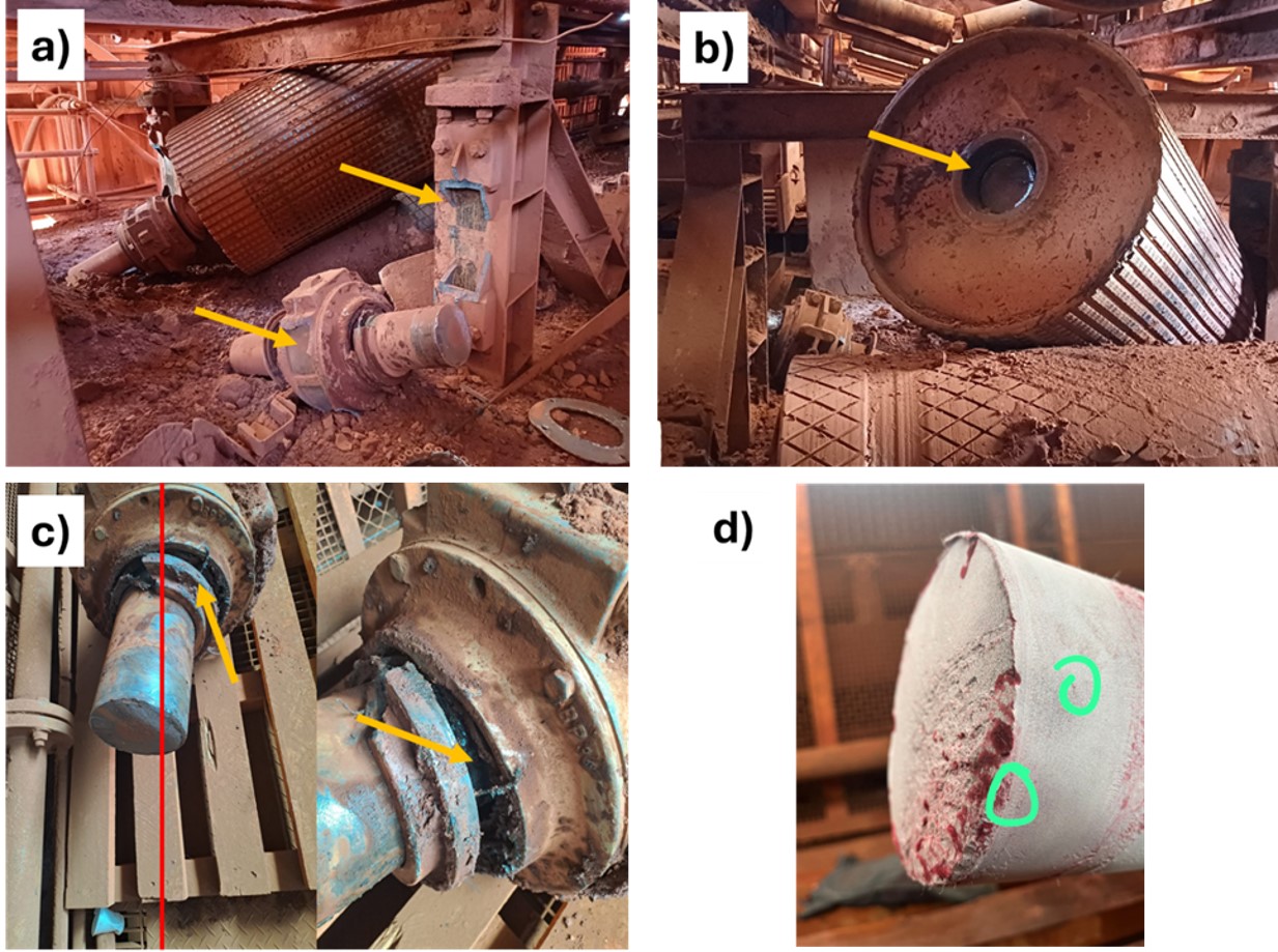
The shaft of a conveyor belt drum and the support of its bearing experienced a failure, as illustrated in Figure 1 (a-d). It was observed that the support of the drum shaft bearing also broke, causing the assembly—part of the shaft with the bearing and drum—to fall to the ground (Figure 1a). Figure 1b shows that the shaft fractured inside the drum. Figure 1c reveals that the shaft bearing also suffered damage, and the shaft bowed to the left, as can be observed in the vertical axis of the figure. Figure 1d shows an initial liquid penetrant inspection on the fractured part and the region near the shaft failure. The test revealed an accumulation of red penetrant liquid, primarily on the outermost diametrical part of the shaft, indicating a potential fracture initiation site.
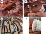
Images of the failure of a conveyor belt drum shaft, causing a production shutdown at the moment of failure. (a) Damaged assembly structure due to the failure, (b) fracture region of the shaft inside the drum, (c) damaged shaft bearing and misaligned shaft in the bearing, and (d) initial visual analysis using liquid penetrant revealing multiple potential fracture initiation points.
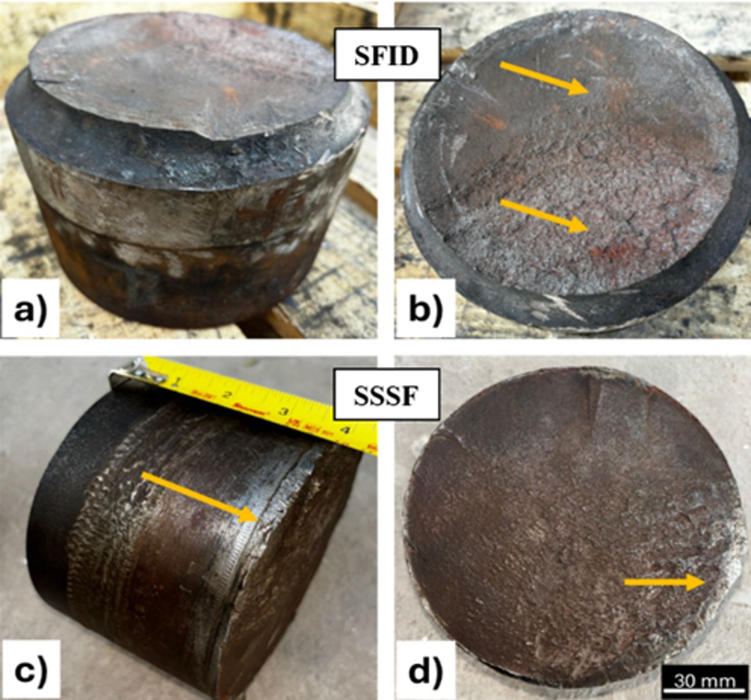
As shown in Figure 2, two fractured shaft samples were received at the Mechanical and Thermomechanical Testing Laboratory (LabEnsaios) of the Federal Institute of Maranhão – IFMA, Brazil. As a first activity, samples were identified as the internal side of the fracture to the drum (ISF), Figure 1 (a-b), and the side separated from the shaft by the fracture (SSF), Figure 2 (c-d). After this, both fractured surfaces were visually inspected. It can be observed that the ISF exhibits a diametral transition zone from 180 to 150 mm in width, and at the end of the curvature radius of 20 mm, the fractured shaft, as shown in Figure 2a. Also, Figure 2b shows that, despite the oxidation over the fracture, there are two regions in the failure surface: one that had high roughness, occupying approximately half of the perimetral area of the fracture, and another region with a visually smoother appearance. Regarding the SSF, intense wear was observed with a thickness of approximately 40 mm (see Figure 2c). Additionally, Figure 2d shows the fractured face with the fractured surface dented due to the possible impact of the shaft with both the support structure of the conveyor system and ground contact. The sections of the fractured parts do not identify the material characteristics.
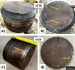
Images of the conveyor drum shaft samples received at LabEnsaios for failure analysis: a) Side of the fracture internal to the drum (ISF), b) Regions of the failure plane (ISF), c) Intense wear and plastic flow of the metal (SSF) and d) Fractured and dented surface (SSF).
2.2. Methodology
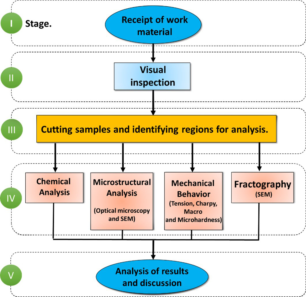
In order to determine the causes of the failure on the shaft, chemical, microstructural, and mechanical characterizations were conducted. Thus, characterization techniques were performed as shown in the flowchart presented in Figure 3.
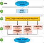
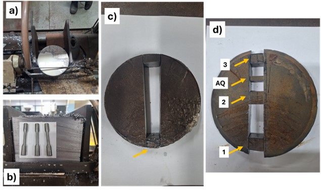
Initially, a solution with acetic acid was used to clean the surfaces, followed by photographic documentation and identification of the failure aspects. Then, several cuts were made in selected shaft regions to extract samples for the subsequent mechanical testing, chemical analysis, and metallographic examination. The tensile and impact test specimens were taken parallel to the central axis of the shaft. Figure 4 (a-d) shows the details and procedures for obtaining the samples.
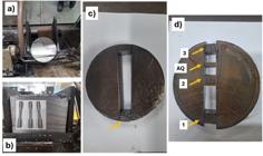
Images of the sample cutting procedures for mechanical testing and failure analysis: a) Beginning of refrigerated cuts on the samples, b) Region used for the preparation of tensile and impact test specimens, c) Removal of the fracture face from the SSSP for microstructural examination, and d) Fractured face of the ISF for fractography, samples 1, 2 and 3, and chemical analysis (CA).
2.2.1. Chemical composition analysis
The chemical composition of the sample was determined by Optical Emission Spectroscopy (OES) using a Shimadzu spectrometer, model PDA 7000. For this, three points were measured on the surface of the sample, taken from the central region of the shaft, and the average weight percentage of each detected element was reported as the chemical composition of the shaft.
2.2.2. Optical and scanning electron microscopy and fractography analysis
The metallographic preparation was carried out following standard procedure, such as cutting the samples, embedding them into Bakelite, grinding with SiC papers ranging from 200 to 1200, and final polishing using 0.5 µm diamond paste. The samples were then chemically etched, employing Nital in a concentration of 2% to generate contrast in the steel microstructure. Subsequently, a Zeiss Axiovert 5 KMAT Optical Microscope was used for image acquisition. Grain size analysis according to the ASTM E112-13 procedure was applied using the comparative method. A Philips XL30 S Scanning Electron Microscope (SEM) operated with a voltage acceleration of 20kV (SE) was used to acquire images, as much as to observe the microstructure as the fracture.
2.2.3. Mechanical testing
On the one hand, Vickers microhardness measurements were conducted using a SHIMADZU microhardness tester, model HMV-2T with a total load of 1 kgf for 13 seconds as load time. For this, six indentations were done in both the center and edge region of the fractured shaft, with a separation between each one in about 1 mm, and the average value was then taken as the hardness of the material in each condition. On the other hand, Charpy Impact tests were conducted using a PANANTEC ATMI Impact Pendulum, 300J hammer, Charpy type A, at 25°C, in accordance with ASTM E23-18. Thus, four tests were performed on test specimens (TS) identified as TS1, TS2, TS3, and TS4. Finally, tensile tests were carried out using samples with a diameter (∅) of 8.75 mm and an effective length (L) of 35.0 mm on an EMIC universal tensile testing machine (300 kN), displacement control, 0.5 mm/min, according to ASTM E8-21.
3. Results and Discussion
3.1. Fractography visual inspection
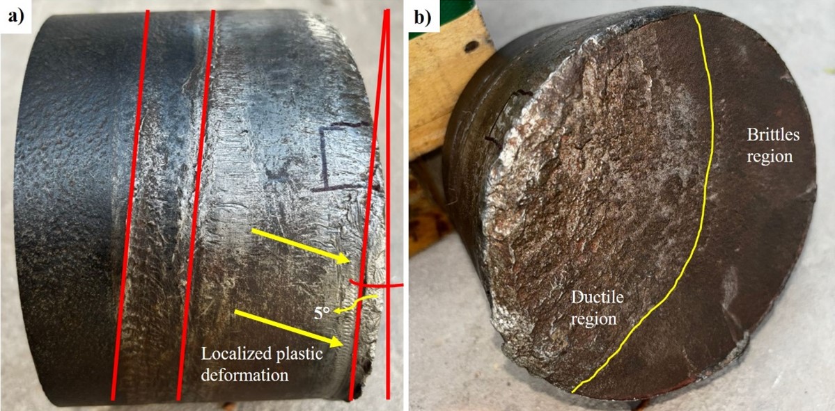
Figure 5 presents the macroscopic visual inspection of the drum shaft fracture surface. It reveals signs of irregular wear and metal flow (i.e., localized plastic deformation) due to the intense contact of the shaft with the internal part of the conveyor drum over the time, as indicated before in the experimental methods section. It is also observed that the worn contact track presents a misalignment of approximately 5° perpendicular to the length of the shaft (see Figure 5a). In addition, Figure 5b shows the complete region of the fracture of the shaft's perimetrical face, indicating that in one moment, the fracture behaved as ductile and then brittle. Although the area is crumpled, some traces suggest fatigue failure propagation, where almost half of the shaft's cross section underwent this process and subsequent catastrophic failure.
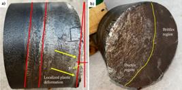
a) Visual profile of shaft wear and b) Macroscopic shaft fracture surface appearance after catastrophic failure.
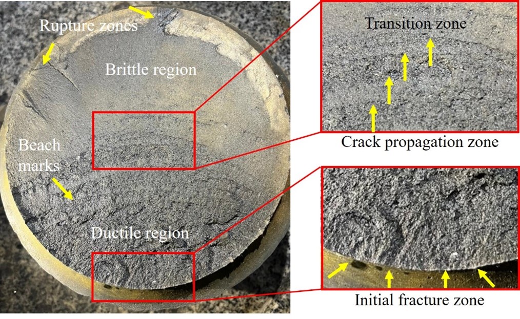
The principal fracture surface features of the failed shaft are displayed in Figure 6. The image reveals in more detail the start region of the fracture, containing multiple crack nucleation sites and propagation striations. It can be observed that the propagation of fatigue failure occurred in a ductile manner. Beach marks are evident up to the transition zone between the ductile and catastrophic failure regions, ending in the outermost diametrical region and showing shear lips. In the area of fracture initiation, some milling marks, highlighted by yellow arrows, are also observed that separate different fronts of initiation of propagation on the fracture surface and ratchet marks along the propagation of the fault where two or more fatigue cracks, nucleated in slightly different planes, join, forming stepped lines on the surface.
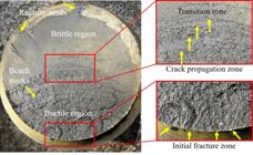
In most drum shaft applications, damage created by shaft deflection often occurs9. Shaft deflection is the bending or flexing of a shaft caused by the sum of the loads on the conveyor system. However, in the current case, the shaft was misaligned, as the localized plastic region has indicated. Due to the continuous working and overloading of the drum shaft at a specific point of contact with respect to the support conveyor system, cyclic loading has caused the shaft to fatigue and rupture. Under typical operating conditions, the influence of cyclic loads on shafts causes fatigue fracture, which is the most frequent mechanism of shaft failure5. Thus, fatigue is understood as the progressive process in which a material is subject to some conditions that introduce stresses and strains after sufficient time fluctuating events, culminating in cracks or complete fracture.
3.2. Chemical composition
According to the results presented in Table 1, the chemical analysis of the material suggests that it corresponds to a structural AISI 4140 steel. This material is an alloyed steel that has greater resistance than common carbon steel grades. The presence of Cr and Mo improve its response to the heat treatment processing such as quenching and tempering, giving to this steel superior mechanical resistance. It is emphasized that the impressive combination of strength and toughness makes 4140 steel a versatile alloy, so numerous industrial applications, such as the manufacture of shafts, make extensive use of it10. There are two main aspects contributing to fatigue failure of the material5. One is selecting the incorrect shaft material, and the second is that the shaft material does not satisfy the standard chemical composition. If the material does not meet the standardized properties indicators as strength, ductility, hardness, toughness and corrosion resistance just achieved after the correct metallurgical processing, it can lead to a premature failure11.
3.3. Microstructural characterization and fractography analysis
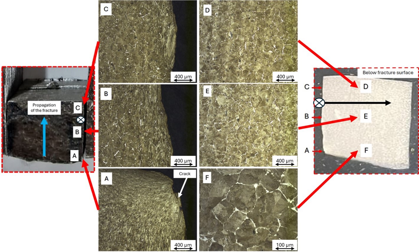
Figure 7 presents the images of the optical metallographic examination of the failed shaft, according to the observation procedure indicated by the letters A to C in the fracture propagation region and letters D to F below the proximity of the fracture surface region. Sections at the edge of samples A, B, and C present elongated grains generated by plastic deformation as well as the presence of a crack in region A. A little further from the edge, a transition zone between elongated grains and equiaxed grains is seen in region B. In an area away from the fracture surface, D, E and F, the grains are equiaxed with an average size of 230 µm, presenting pearlite and contoured by pro-eutectoid ferrite. This microstructure advises that the shaft was thermomechanically processed at a higher temperature (e.g., probably above 1000 °C) and then air cooled. This microstructure for an AISI 4140 steel differs from the expected one after applying an obvious quench and temper heat treatment, going far away from the material processing specifications for drum shaft applications. For mechanical cycling loading in motion systems, the AISI 4140 steel has been successfully applied, being manufactured utilizing open-die forging and specific heat treating for producing heavy parts combining outstanding strength and ductility and also good cracking resistance due to the superior impact properties12 when compared to other plain carbon steels. Badaruddin et al.13 have shown that the final microstructure of an AISI 4140 can be improved by modifying the quench and temper thermal processing route for manufactured products such as shafts. By applying a double quenching-tempering process, a tempered-martensite microstructure in a ferritic matrix can be obtained with a sharp increase in strength resistance and ductility.
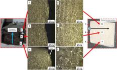
Metallographic analysis of the sample from the axis close to the edge of the fracture surface initiation and proximity from the fracture surface.
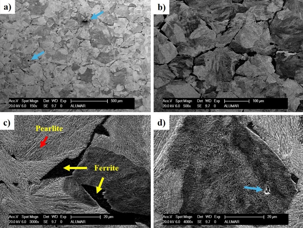
Figure 8 shows the SEM images of the central region and the proximity region from the fracture surface of the failed shaft. The microstructural features of the equiaxial pearlite grains (light regions) surrounded by pro-eutectoid ferrite (dark areas) can be seen better. Additionally, voids and/or inclusions can be verified, as the blue arrows indicate. With increasing the magnification, Figures 8b), c) and d), details of the pearlitic structure and color variations on the gray scale can be observed, a well-known material characterized by presenting different crystallographic directions of the pearlitic grains.
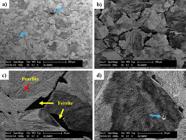
SEM images for the sample near the fracture surface a-d): a and d) Non-metallic inclusions observed at low and high magnification in the microstructure; b) Identification of the microstructural condition showing grains of perlite surrounded by ferrite and c) higher magnification presenting the details of ferrite and pearlite.
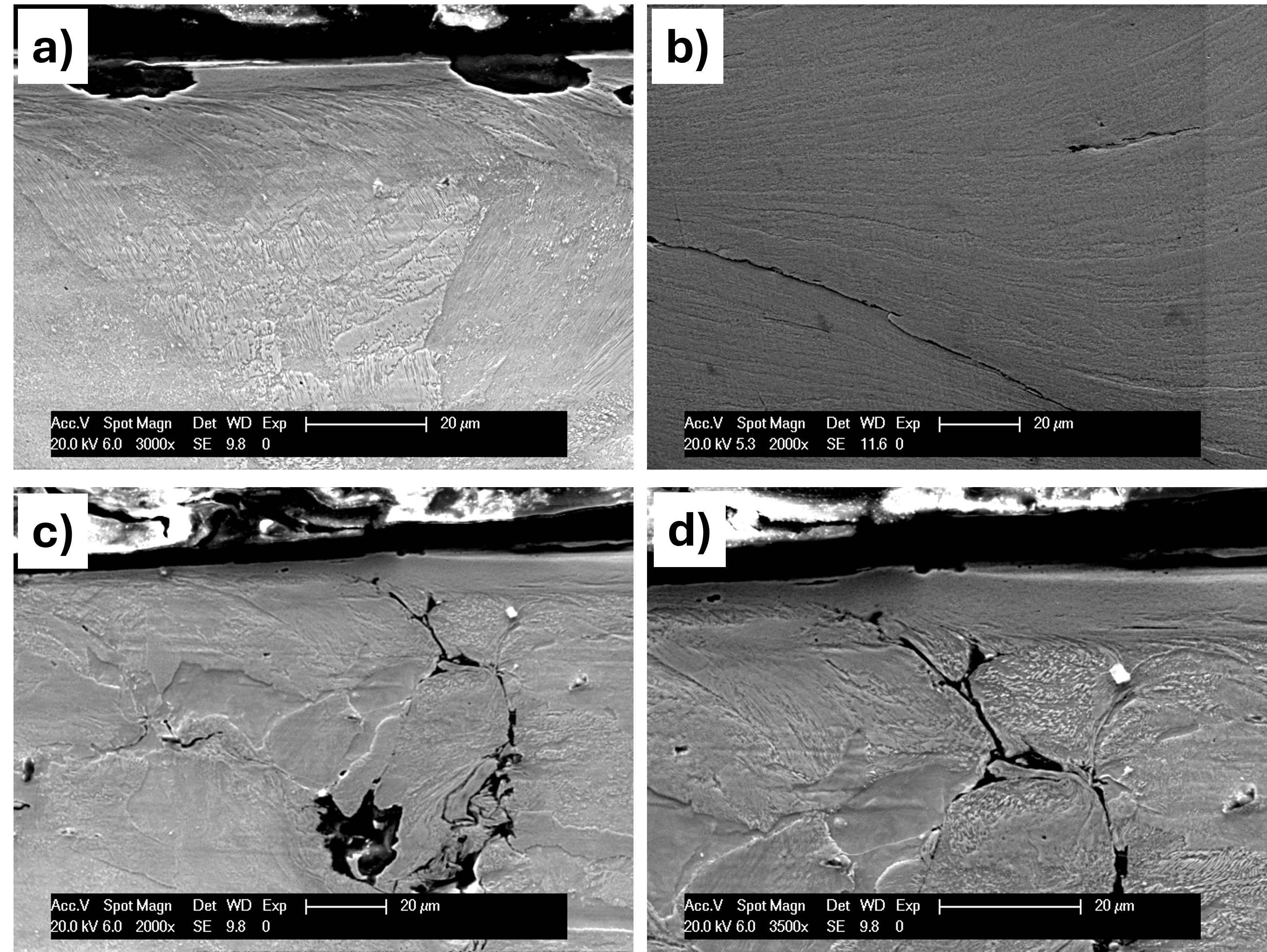
The analysis of the deformed region can be seen in Figure 9. In the case of Figure 9a, it shows a region with pearlitic grains that underwent intense plastic deformation, as the flow lines in the microstructure allows to observe it. A long crack in the direction of deformation can be seen in Figure 9b. Figures 9 (c-d) show the propagation of a transgranular crack and a region showing the presence of pores and inclusions inside it. The intense plastic deformation that the material supported finally resulted in the nucleation of microcracks that fast propagated until the fracture was reached. When defects like microvoids or microcracks form, grow, and eventually coalesce into macrocracks, the material's mechanical properties often deteriorate. Thus, material damage is strongly controlled by a variety of metallurgical and processing factors such as alloy composition, microstructure, temperature, strain, strain rate, stress state, etc14.
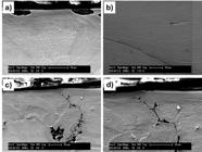
a) SEM image of intense deformation region that has led to the failure of the shaft, b) Image of crack propagation along the material flow, c) and d) presence of intergranular cracks.
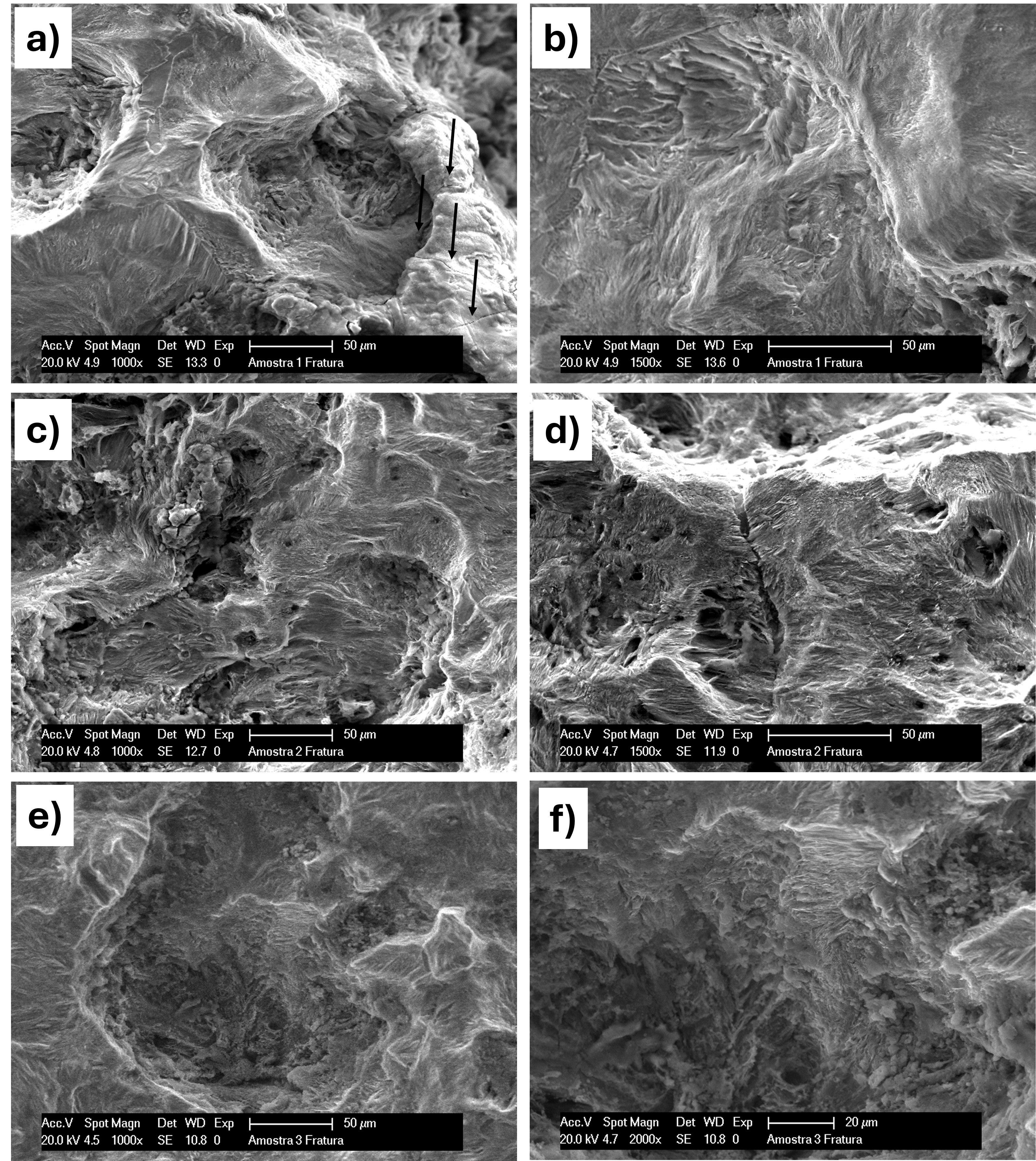
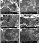
The fractography SEM images are shown in Figure 10, obtained as indicated in Figure 4. In the case of the sample 1, it characterizes the beginning of the fatigue process, in which the presence of several microcracks and dimples characteristic of ductile fracture, as well as fatigue striations, can be observed in Figure 10 (a-b). In sample 2, the transition zone between the fatigue process and the catastrophic failure is shown in Figures 10 (c-d). Also, the presence of valleys and dark spots of inclusions and/or voids and microcracks at the end of the transition zone can be seen. Finally, region 3 is characterized by the catastrophic failure zone, a smoother surface with characteristics of a more brittle fracture is observed. Along the fracture surface, the fracture propagation mechanism shifts to a mixed mechanism consisting of a few intergranular fracture regions and voids. In consequence, these SEM fractography images have shown that the main fracture mechanism is quasi-cleavage15, a possible fatigue propagation mechanism for the AISIS 4140 steel16. Marcomini et al.17 found that the combination of wear, contact-fatigue, impact fatigue and overload have been the causes of the premature failure of a hot-forged SAE 4140 steel kingpin truck component. They also observed that the variation and changes in loads as severe operational conditions have promoted irregular deformation in the cross section of the kingpin. Thus, a correlation between their results and present findings can be done about the failure mode of the shaft.
3.4. Mechanical characterization
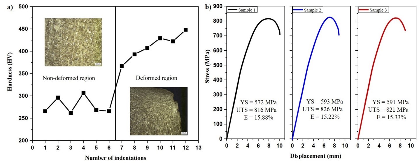
The microhardness profile of the undeformed and deformed regions is shown in Figure 11a. The measurements were made on the surface of the sample analyzed by optical microscopy in the direction A to E of Figure 8. A significant increase in the microhardness values can be observed in the deformed region. It is known that the increase in hardness in a plastically deformed region is a consequence of the increase in dislocation density leading to work hardening of the material. High work hardening is synonymous with embrittlement and consequent facilitation of the emergence of cracks when subjected to cyclic loads. Respect to the mechanical behavior, Figure 11b presents the main values of the yield strength (YS), ultimate tensile strength (TS) and the total elongation to fracture (E), all these values were determined directly by the equipment software and checked. The average values were YS = 585.6 MPa, TS = 821.4 MPa and E = 15.48%. It is observed that this steel presented higher resistance values that are comparable with those ones for the structural steel AISI 4140, and higher than the usual carbon steel AISI 104518. However, the elongation is considered a little lower for AISI 4140 than is expected for values of 25%. Also, it has been stated that the gradual reduction in strength and cycling softening behavior until failure in low working cycles for AISI 4140 steel is the direct consequence of the microstructure, being very sensitive the material to cyclic plastic deformation19.
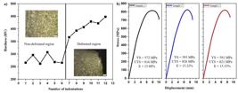
Mechanical behavior of the fractured shaft: a) Vickers microhardness profile and b) Engineering stress-strain curves.
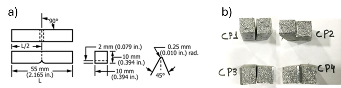
As Table 2 shows, the energy absorption values are low, leading to brittle fractures, which show that this material cannot be exposed to excessive impacts. The fractures were similar for all samples, which correspond to the 10% fracture profile as per the guide fracture shear appearance graphs for comparison of the same according to the ASTM A370-21 standard over the sample configuration shown in Figure 12.
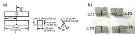
Charpy Impact Test: a) V-notch specimens full size dimensions, and b) appearance of shear fractures of Charpy impact test specimens.
4. Conclusions
The failure analysis of the conveyor drum shaft, used for mining operation, has revealed that the fracture originated from a fatigue process. The visual inspection and the metallographic analysis revealed irregular wear and intense plastic deformation due to a misalignment of the shaft in the drum with multiple crack nucleation points observed in the region where the failure initiated. This caused metal flow towards the fracture initiation region and work hardening, enabling the nucleation of several microcracks and cracks, which subsequently propagated, and led to the failure initiation. The chemical analysis allowed to identify the material as AISI 4140 structural steel, which exhibits good mechanical behavior. However, current ferrite and pearlite microstructure hardly allow to achieve the required mechanical behavior for mining operations. Thus, the measured mechanical properties have indicated that the lack of mechanical resistance has contributed to the brittleness after the reduction of the shaft's cross-sectional area. Finally, it is stated that the failure of the shaft occurred through a fatigue process, passing through a ductile region until reaching the transition zone, resulting in a catastrophic brittle failure. Notwithstanding, it is always recommended to review the assembly and continuously monitoring the alignment of the shafts in the conveyor drum. Mechanical components used in the assembly of industrial equipment need to undergo quality control regarding the mechanical and metallurgical properties, keeping low economical and/or environmental losses.
5. Acknowledgments
authors acknowledge the support the Brazilian National Council for Scientific and Technological Development (CNPq), the Research and Support Foundation of Maranhao (FAPEMA), Coordenacao de Aperfeicoamento de Pessoal de Nivel Superior-Brasil (CAPES) and PRPGI at IFMA
6. References
- 1 CEMA: Conveyor Equipment Manufacturers Association. Belt Conveyors for Bulk Materials. 5th ed. Rockville, MD: CEMA; 1997.
-
2 ProCal Innovations LLC. Conveyor pulley selection guide, revision 2.0 [Internet]. 2021 [cited 2025 Feb 02]. Available from: https://www.pcimfg.com/
» https://www.pcimfg.com/ - 3 Affolter C, Piskoty G, Koller R, Zgraggen M, Rütti TF. Fatigue in the shell of a conveyor drum. Eng Fail Anal. 2007;14:1038-52.
- 4 McHenry HI, Rolfe ST. Fracture control practices for metal structures (NBS IR 79-1623). Maryland: National Bureau of Standards; 1980.
- 5 Hou N, Ding N, Qu S, Guo W, Liu L, Xu N, et al. Failure modes, mechanisms and causes of shafts in mechanical equipment. Eng Fail Anal. 2022;136:106216.
- 6 Pineau A, Benzerga AA, Pardoen T. Failure of metals I: brittle and ductile fracture. Acta Mater. 2016;107:424-83.
- 7 Novile R. Failure analysis in metallic materials. Metals (Basel). 2023;13:1374.
- 8 Miranda RS, Cruz C, Cheung N, Cunha APA. Fatigue failure analysis of a speed reduction shaft. Metals (Basel). 2021;11:856.
- 9 Yalavarthi V, Kandregula R, Ram KSR. Experimental analysis of stress, strain and deformation on different types of conveyor belt pulleys. An analysis conducted at Visakhapatnam Steel Plant. Aust J Basic Appl Sci. 2010;10:715-9.
-
10 Otai J. Choosing the right steel: advantages of 4140 steel for shafts [Internet]. 2023 [cited 2025 Feb 02]. Available from: https://www.otaisteel.com/4140-steel-for-shafts/
» https://www.otaisteel.com/4140-steel-for-shafts/ - 11 Atxaga G, Irisarri AM. Failure analysis of the end of a shaft of an engine. Eng Fail Anal. 2010;17:714-21.
- 12 Skubisz P, Lisiecki L. Effect of forging sequence and heat treatment on microstructure of high-duty power-plant shaft made of Cr-Mo ultra-high strength steel. J Min Metall. 2023;59:299-314.
- 13 Badaruddin M, Pratama RP, Harnowo S. Effect of single and double quenching-tempering heat treatments on microstructures and tensile strength of AISI 4140 in annealing condition. AIP Conf Proc. 2023;2592:020016.
- 14 Salas-Reyes AE, Mejía I, Cabrera JM. Effect of Ti microaddition on cavitation behavior during uniaxial hot-tensile of Fe-22Mn-1.5Al-1.3Si-0.5C austenitic TWIP steel. MRS Online Proceedings Library. 2016;1812:123-8.
- 15 Hull D. Fractography: observing, measuring and interpreting fracture surface topography. Cambridge: Cambridge University Press; 1999.
- 16 Vargas-Arista B, Teran-Guillen J, Solis J, García-Cerecero G, Martínez-Madrid M. Normalizing effect on fatigue crack propagation at the heat-affected zone of AISI 4140 steel shielded metal arc weldings. Mater Res. 2013;16:772-8.
- 17 Marcomini JB, Baptista CARP, Pascon JP, Teixeira RL, Medina PC. Failure analysis of a hot forged SAE 4140 steel kingpin. Int J Eng Res Sci. 2016;2(6):102-9.
- 18 Quan G, Tong Y, Luo G, Zhou J. A characterization for the flow behavior of 42CrMo steel. Comput Mater Sci. 2010;50:167-71.
- 19 Badaruddin M, Wardono H, Wang CJ, Rivai AK. Improvement of low-cycle fatigue resistance in AISI 4140 steel by annealing treatment. Int J Fatigue. 2019;125:406-17.