Abstract
In order to improve steel quality, it is necessary to increase the cleanliness of the liquid steel; that is, to reduce the number and size of the inclusions in the liquid steel, as well as to control their chemical composition. For this purpose, processes (with different operating costs) are used, such as the bubbling of inert gas in the steel ladle and its treatment in the vacuum degasser RH. This article deals with inclusion removal through an argon purging process and RH treatment, and provides a comparison of their effectiveness using industrial data and a mathematical model. The inclusion count shows a strong exponential decay for RH treated heats with chemical heating, as expected. The same behavior is not seen for RH treated heats without chemical heating as well as an argon purging process. It is suggested that in the later cases, there could exist competition between inclusion removal and inclusion generation from sources, such as refractory-slag-metal interaction and open eye atmosphere metal interaction. It has been concluded that the RH and the argon purging processes are both able to reduce the amount of inclusions. However, the bubbling process would require a much smaller gas flow rate to avoid open eye formation.
Keywords:
inclusions; RH; bubbling station
Keywords:
inclusions; RH; bubbling station
1. Introduction
The composition, quantity and size distribution of nonmetallic inclusions strongly influence the chemical and physical properties of steel, such as fatigue, machinability and corrosion resistance, whereby improving steel quality implies increased liquid steel cleanliness (Yang et al., 2014YANG, C.; TANG, F.; HE, T.; FU, Q. Water Model on Fine Inclusion Removal by Bubble Flotation in RH Refining Process. Applied Mechanics and Materials, Swiss, v. 528, p. 107-111, 2014.). Many processes in secondary metallurgy, such as lade furnace, VOD, RH and argon purging are used with the purpose of impurities removal.
The inert gas injection is commonly practiced in ferrous and non-ferrous metal secondary metallurgy processes and this technique is used for obtaining temperature and chemical homogeneity of the liquid metal and for helping the removal of secondary phases and impurities dispersed in liquid metals (Wang et al., 1996WANG, L.; LEE, H. G.; HAYES, P. Prediction of the optimum bubble size for inclusion removal from molten steel by flotation. ISIJ International, v. 36, n. 1, p.7-16, 1996.). Although inert gas injection is a low-cost process, it can jeopardize the steel quality, since if the gas is not well controlled, the steel can be exposed to an oxidizing atmosphere, which could imply in inclusion generation.
Beyond the argon purging process (APP), the attention given to the RH process (which is normally used for dehydrogenation, denitrogenation and decarburation) has been growing due to its strong ability for removing inclusions (Yang et al., 2013YANG, C.; TANG, F.; HE, T.; FU, Q. Physical Simulation of Inclusions Removal in 180t RH Degasser. Advanced Materials Research, v. 750-752, p. 375-379, 2013.). One advantage of this processes in comparison to the APP is that it does not present the same oxidizing atmosphere exposition risk as long as vacuum exists inside the treatment chamber.
The development of the APPs has been focusing on two main conditions: obtaining small bubbles and good mixing. Small bubbles imply in a large gas-liquid interface, resulting in a high probability of adhesion between the inclusion and bubbles; a good mixing condition improves the mass transfer efficiency (Zhang and Taniguchi, 2000ZHANG, L.; TANIGUCHI, S. Fundamentals of inclusion removal from liquid steel by bubble flotation. International Materials Reviews, v. 45, n.2, p.59-82, 2000.). The larger the gas bubble, the lower the particle removal rate is, so smaller bubbles can favor inclusion removal (Zhang et al., 2016ZHANG, L.; TANIGUCHI, S.; MATSUMOTO, K. Water model study on inclusion removal from liquid Steel by bubble, flotation under turbulent conditions. Ironmaking and Steelmaking , v.29, n. 5, p. 326-336, 2016.).
Söder et al. (2004)SÖDER, M.; JÖNSSON, P.; JONSSON, L. Inclusion Growth and Removal in Gas-stirred Ladles. Steel Research International, v.75, n.2, p. 128-138, 2004. studied the growth and removal of inclusions in the APP through a static model and suggested that the turbulent collision is the most important phenomena, improving as the size difference between the inclusions increases.
Cao and Nastac (2018)CAO, Q.; NASTAC, L. Numerical modelling of the transport and removal of inclusions in an industrial gas-stirred ladle. Ironmaking and Steelmaking, v.45, n. 10, p.984-991, 2018. have studied the inclusions transport and removal in a gas stirred ladle trough, a 3D computational fluid dynamics (CFD) model. They concluded that the absorption of the inclusions by the slag is the main inclusion removal mechanism, and that raising the gas flow rate favors this mechanism.
Marins (2011)MARINS, A. M. F. Modelagem física e computacional do fluxo de aço em panela com agitação por gás inerte, com ênfase na separação de inclusões. 2011. 111 f. Dissertação (Mestrado em Engenharia de Materiais) - Universidade Federal de Ouro Preto, Ouro Preto, 2011. highlighted that there is a possibility of steel contamination (possible steel re-oxidation and hydrogen and nitrogen pick up) during bubbling due to the steel-slag-atmospheric air interaction, so it is important to control the gas flow rate in order to avoid the metal-slag emulsion occurrence and the open eye onset.
Shirabe and Szekely (1983)SHIRABE, K.; SZEKELY, J. A mathematical model of fluid flow and inclusion coalescence in the RH vacuum degassing system. Transactions ISIJ, v. 23, p. 465-474, 1983. performed a mathematical simulation of an RH system and observed that the flow in the ladle is highly turbulent (mainly below the down leg), emphasizing that the RH is an excellent mixer. High turbulence and non-oxidizing atmosphere during treatment may indicate that this equipment could be ideal for inclusion removal.
Miki et al. (1997)MIKI, Y.; THOMAS, B. G.; DENISSOV, A.; SHIMADA, Y. Model of inclusion removal during RH degassing of steel. Iron and Steelmaker, v. 24, n. 8, p. 31-38, 1997. developed a mathematical model for predicting the evolution of inclusion size and spatial distribution during the steel treatment in RH. According to them, one minute after the aluminum addition, it is possible to find large dendritic inclusions, but after fifteen minutes, these inclusions disappear, and larger aggregates are to be found in exchange. The authors concluded that the large inclusions are able to float, while the smaller ones aggregate. These aggregates formed by the small inclusions float with increasing difficulty because, as the steel fills the blank spaces between the particles, their resulting density approximates the steel density. Later, Lascosqui (2006)LASCOSQUI, P. S. B.Avaliação da limpidez do aço líquido através da modelagem matemática do desgaseificador - RH da Companhia Siderúrgica de Tubarão - CS T. 2006. 86 f. Dissertação (Mestrado em Engenharia de Materiais) - Universidade Federal de Ouro Preto, Ouro Preto, 2006. evaluated the influence of circulation time on the steel cleanliness, concluding that after 300 seconds, the inclusion concentration is almost independent of the initial concentration.
These studies suggest that both processes can be used for inclusion removal from liquid steel. However, although the inclusion removal mechanisms have been discussed, comparison between both methods are scarce and little is discussed about the necessity of using one process or the other for achieving a certain level of steel cleanliness. This last consideration is important, since the RH process is usually more costly than the bubbling process. This article provides a comparison between the two processes.
2. Materials and methods
Mathematical simulations and industrial data collection were made in order to evaluate the inclusion removal efficiency of APP and RH processes. The mathematical simulation was proposed to analyze the steel flux in the vessel and ladle. The velocity and dissipation of turbulent kinetic energy rate fields were obtained for the argon purging and RH process. The industrial data were collected manually in six heats during the APP and RH treatments. Then, an inclusion count was made to determine the inclusion removal during the processes. Combining these results, it is possible to understand the processes efficiency and the probable causes for differences observed.
2.1 Mathematical simulations
Mathematical simulations of steel flow in a 224 t liquid steel ladle have been performed for APP (gas flow rate of 250 NL/min) and RH (gas flow rate of 100 Nm3/h) processes. Figure 1 shows the main dimensions of the ladle and RH reactor.
Simulations have been performed using CFX 19.1 (Ansys®) software. The model was the k-ε turbulence model for the continuous phase (liquid), while for the dispersed phase (gas), the zero-equation model is adopted. For the RH reactor, the Ishii-Zuber models were adopted for the drag force with the virtual mass coefficient equaling 0.25. The Frank model for the wall lubrication force and Favre average for the turbulent dispersion force, according to Peixoto (2019)PEIXOTO, J. J. M. Análise da turbulência e do comportamento metal-escória no interior de um reator RH e sua influência sobre a reação de dessulfuração do aço. 2019. 205 f. Tese (Doutorado em Engenharia de Materiais) - Universidade Federal de Ouro Preto, Ouro Preto, 2019. were also used. For the ladle APP simulation, only the drag and turbulent dispersion forces were considered.
The values of argon (25 ºC) and steel (1600 ºC) properties used in this simulation are the same given by Peixoto (2019)PEIXOTO, J. J. M. Análise da turbulência e do comportamento metal-escória no interior de um reator RH e sua influência sobre a reação de dessulfuração do aço. 2019. 205 f. Tese (Doutorado em Engenharia de Materiais) - Universidade Federal de Ouro Preto, Ouro Preto, 2019. and are described in Table 1. It is assumed that the gas bubble diameter is constant and is calculated from the experimental correlation given by Equation (1), from Johansen and Boysan (1998)JOHANSEN, S.T.; BOYSAN, F. Fluid dynamics in bubble stirred ladles: part II. Mathematical modeling. Metallurgical and Materials Transactions B, v. 19B, p.755-764, 1988. . The bubble size was around 7.5 mm for APP and ranged from 17 mm to 47 mm for RH reactor due to gas expansion caused by the sharp pressure drop, in accordance with Peixoto (2019)PEIXOTO, J. J. M. Análise da turbulência e do comportamento metal-escória no interior de um reator RH e sua influência sobre a reação de dessulfuração do aço. 2019. 205 f. Tese (Doutorado em Engenharia de Materiais) - Universidade Federal de Ouro Preto, Ouro Preto, 2019..
Where: G - gas flow rate (Nm3/s); g - acceleration of gravity (m/s2);
For the RH reactor in a symmetrical condition, only half of the reactor was considered. The boundary conditions applicable to the problem are: (i) Non-slip condition applied to all walls, regions where the fluid has zero velocity; (ii) Symmetrical Condition: in this region the velocity component's normal to the boundary is zero; (iii) Injection nozzles: gas flow rate in kg/s (considering symmetrical conditions), subsonic flow regime with a turbulence intensity of 5%; (iv) Free slip condition on ladle free surface; (v) Vacuum chamber surface: opening condition, with pressure equal to the applied vacuum.
For APPs, the boundary conditions applicable to the probletm are: (i) Non-slip condition applied to all walls, regions where the fluid has zero velocity; (ii) porous plug: gas flow rate in kg/s, subsonic flow regime with a turbulence intensity of 5%; (iii) ladle free surface: opening condition, with relative pressure equal 0 Pa.
The element sizing of the grid was set like Peixoto (2019)PEIXOTO, J. J. M. Análise da turbulência e do comportamento metal-escória no interior de um reator RH e sua influência sobre a reação de dessulfuração do aço. 2019. 205 f. Tese (Doutorado em Engenharia de Materiais) - Universidade Federal de Ouro Preto, Ouro Preto, 2019. for the RH simulation. For APP a densely packed mesh was applied in the region above the porous plug. Thus, the calculation domain had approximately 380 thousand grid nodes (930 thousands grid elements), which is sufficiently fine to give reasonably grid-independent results.
2.2 Industrial tests
The present article evaluates inclusion behavior during aluminum and silicon killed steel processing; these are steels used to produce civil construction plates with 0.13-0.17% carbon and 0.8-0.9% manganese. Six heats were produced in the routes below in secondary metallurgy treatments as showed in Table 2: BOF - RH degasser - slab continuous casting machine BOF - bubbling station - slab continuous casting machine.
3. Results and discussion
Lollipop samples were taken manually in all the heats in different treatment moments, as can be seen in section 3.2. The samples were prepared by sanding and polishing according to the ASTM E3 standard. Then, an inclusion count and analyses were made using a MEV/EDS (ASPEX) with an FEI inclusion analyzing software (“Aspex Explorer”) in a scanned area of 2.33x107 µm2. The inclusions with less than 2µm diameter were declassified.
3.1 Mathematical simulation
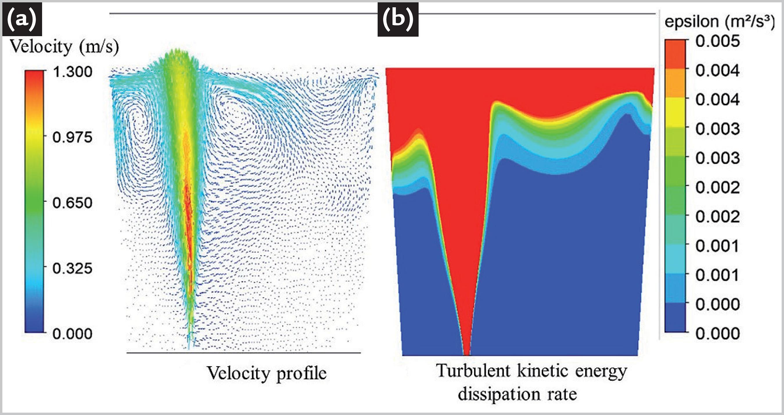
Figures 2 and 3 show the results of the mathematical simulation for the steel flow in the stirred ladle and in the RH, respectively. The resulting profiles are quite different, and they may indicate that the inclusion removal efficiency of these processes may differ considerably.
It can be noticed that the region with the larger steel velocities in the stirred ladle is located mainly above the porous plug (Figure 2); this same region depicts the larger rates of dissipation of turbulent kinetic energy, which is due to gas bubble swarming.
The higher dissipation of turbulent kinetic energy rate in this area may indicate that it favors the collision and aggregation of inclusions, but the gas bubble traffic time to the surface may not be large enough, so this phenomena could occur before the inclusions reach the slag layer. In addition, some vortices are observed close to the slag layer, which may indicate that the inclusions, after reaching this layer, may be carried back to the center of the bath.
In the RH (Figure 3), the regions with larger velocities and rate of dissipation of turbulent kinetic energy are better distributed as compared with the gas stirred ladle. There are three main regions (at the up leg, at the bottom of the ladle and under the down leg, as also pointed out by Shirabe and Szekely (1983)SHIRABE, K.; SZEKELY, J. A mathematical model of fluid flow and inclusion coalescence in the RH vacuum degassing system. Transactions ISIJ, v. 23, p. 465-474, 1983. and Lascosqui (2006)LASCOSQUI, P. S. B.Avaliação da limpidez do aço líquido através da modelagem matemática do desgaseificador - RH da Companhia Siderúrgica de Tubarão - CS T. 2006. 86 f. Dissertação (Mestrado em Engenharia de Materiais) - Universidade Federal de Ouro Preto, Ouro Preto, 2006.) where the rate of dissipation of turbulent kinetic energy is high, favoring the collision and agglomeration of inclusions.
The flow pattern suggests that then inclusions or clusters are carried away towards the floating slag layer and vortices that could carry the inclusions back to the bath after reaching the slag layer are not observed. There is a favorable combination of stirring intensity and flow pattern, which is not observed in the ladle.
3.2 Industrial tests
Concerning the industrial tests, the following figures show the evolution of inclusion content along the treatment. Q⁄Qo is the fraction of inclusions remaining in the steel (as compared with the initial inclusion count). The results are presented as the global count (concerning all the inclusion sizes) and number of inclusions by inclusion size ranges.
3.2.1 Heats treated in APP station
Data for Heat #1 ( APP) are given in Figure 4. Data for Heat #2 (APP) are given in Figure 5.
Ratio between the inclusion counting and the initial inclusion quantity Q⁄Qo - Heat # 1: (a) global Q⁄Qo ; (b) according to the inclusions size.
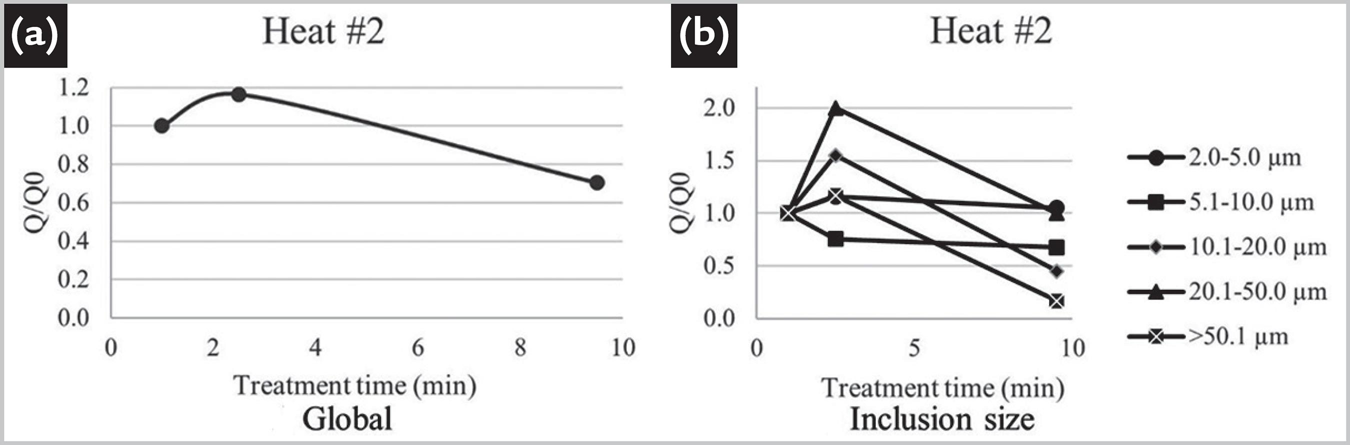
Ratio between the inclusion counting and the initial inclusion quantity Q⁄Qo - Heat # 2: (a) global Q⁄Qo ; (b) according to the inclusions size.
In both treatments, an increase in the inclusion quantity and a further decrease is observed, which indicate that inclusions were generated during the treatment.
Heats #1 and #2, produced in the APP station, show an initial increase of the inclusion counting which may be due to steel re-oxidation by the open eye and stronger interaction with the floating slag. The heats show a small decrease of 22% (average) of the number of inclusions at the end of the treatment.
3.2.2 Heats treated in RH with chemical heating
Heats #3 and #4 refer to RH treatment with chemical heating (aluminum addition plus oxygen blowing). The shown data are for samples taken after oxygen blowing. Data for Heat #3 are given in Figure 6. Data for Heat #4 are given in Figure 7.
Ratio between the inclusion counting and the initial inclusion quantity Q⁄Qo - Heat # 3: (a) global Q⁄Qo ; (b) according to the inclusion size.
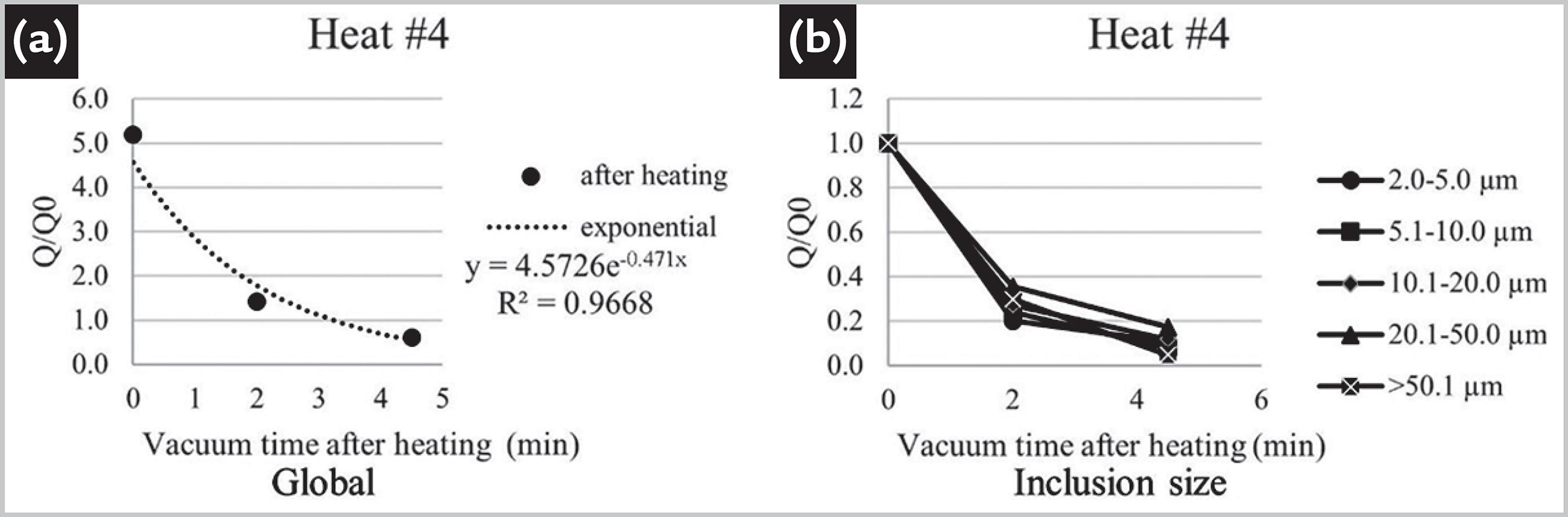
Ratio between the inclusion counting and the initial inclusion quantity Q⁄Qo - Heat # 4: (a) global Q⁄Qo ; (b) according to the inclusion size.
As heats 3 and 4 have gone through chemical heating (aluminothermy), after this procedure the inclusion content increases more than 400% (average), dropping exponentially right afterwards. This behavior was observed in every inclusion size range.
The equations in Figures 8 and 9 relate to the work of Aoki et al. (2005)AOKI, J.; ZHANG, L.; THOMAS, B. G. Modeling of inclusion removal in ladle refining. In: AISTech and ICS Conference Proceedings, May 8-12, 2005, Charlotte. Proceedings […]. Charlotte, North Carolina: AIST, 2005. p. 319-331., where the authors studied the inclusion removal during argon purging in a steel ladle. The authors evaluated a deoxidation constant such as:
Ratio between the inclusion counting and the initial inclusion quantity Q⁄Qo - Heat # 5: (a) global Q⁄Qo ; (b) according to the inclusion size.
Ratio between the inclusion counting and the initial inclusion quantity Q⁄Qo - Heat # 6: (a) global Q⁄Qo ; (b) according to the inclusion size.
3.2.3 Heats treated in RH without chemical heating
Heat # 5 and #6 refer to RH treated steels but without chemical heating; however, some aluminum is added to complete the deoxidation process. The initial inclusion counting is given by the previous deoxidation process. Data for Heat #5 are given in Figure 8. Data for Heat #6 are given in Figure 9.
Heat number 5 shows an increase in the number of inclusions of the 2-5µm range right after the aluminum addition until the end of the treatment and this behavior is not observed in Heat #6. In the other ranges, a decrease in the initial inclusion amount is observed in Heats 5 and 6.
Although the initial inclusion counting of Heat #6 is almost twice that of the initial inclusion content of Heat #5, the final inclusion counting is almost the same, which suggests that the initial inclusion content does not influence the final result. For vacuum times of approximately 20 min (typical for most of the treatments), it is possible to achieve a reduction of 60% of the initial inclusion amount.
According to Yang et al. (2015)YANG, C.; TANG, F.; SHEN, M. Water model study on removing inclusion from molten steel by bubble attachment in RH degasser. Telkomnika, v.13, n. 2, p. 670-677, 2015., the inclusions removal in an RH reactor is directly proportional to the treatment time, so the inclusion removal would always decrease as long as the vacuum and steel mixing go on. In disagreement to Yang et al. (2015), the present article shows that after some minutes under treatment, the inclusion number asymptotically tends to a fixed value.
The initial amount of inclusions in Heats #3 to #5 is quite similar. However, an exponential decay is not observed for Heats #5 and #6, and a logarithmic fitting is more appropriate, even though the samples were taken from the same equipment. This difference can be assigned to the timing of deoxidation, which in Heats 3 and 4 was performed after the chemical heating and in Heats 5 and 6 during tapping of the BOF. This is the reason why the initial inclusion count of the various heats is four times lower than after chemical heating.
No clear tendency was observed as far as bubbling station data are concerned, so it is not possible to compare this process to the ones studied by Aoki et al. (2005)AOKI, J.; ZHANG, L.; THOMAS, B. G. Modeling of inclusion removal in ladle refining. In: AISTech and ICS Conference Proceedings, May 8-12, 2005, Charlotte. Proceedings […]. Charlotte, North Carolina: AIST, 2005. p. 319-331.. Nevertheless Aoki et al. (2005) suggest that the bubbling station is as capable of removing the inclusions as the RH, but this performance would only be achieved with a gas flow rate seven times lower than the one used in this study. This excessive flow rate may have caused competition between the inclusion removal process and incorporation phenomena, such as emulsification and reoxidation in Heats 1 and 2.
4. Conclusions
The APP and RH processes can be used for inclusion removal from liquid steel, even when aluminothermic chemical heating is required. As shown by the analysis of industrial data, this removal comes with a much higher predictability and efficiency in the RH as compared to the bubbling station; a decrease of 60% is achievable in about twenty minutes under vacuum.
The mathematical simulations showed that the higher dissipation of turbulent kinetic energy rate in the RH in comparison with the APP indicates that this equipment has a greater efficiency in aggregating inclusion. Besides, recirculating flow was observed in the APP simulation indicating that inclusions may return to the metal bath after reaching the slag layer. Also, concerning the RH treatment, industrial data showed that in spite of the different initial inclusion content, after some minutes under treatment, the inclusion numbers in the heats are almost the same, which means that the initial amount of inclusions does not influence the final amount.
An exponential decay of inclusion count is noticed for RH treated steels with chemical heating, just as expected. This behavior has not been found for RH treated steels without chemical heating. For the latter, it is presumed that there occurs a competition process between inclusion generation and inclusion removal, which leads to an asymptotic decay to a specific value.
From comparison with Aoki et al. (2005)AOKI, J.; ZHANG, L.; THOMAS, B. G. Modeling of inclusion removal in ladle refining. In: AISTech and ICS Conference Proceedings, May 8-12, 2005, Charlotte. Proceedings […]. Charlotte, North Carolina: AIST, 2005. p. 319-331. data, it is suggested that it would be possible to obtain an inclusion removal at the bubbling station as efficient as at the RH. Nevertheless, for achieving this purpose, a flow rate around seven times smaller than the one used in this study is required.
Acknowledgements
To Gerdau for providing support for this work. To the Brazilian funding agencies Fapemig, CNPq and Capes.
References
- AOKI, J.; ZHANG, L.; THOMAS, B. G. Modeling of inclusion removal in ladle refining. In: AISTech and ICS Conference Proceedings, May 8-12, 2005, Charlotte. Proceedings […] Charlotte, North Carolina: AIST, 2005. p. 319-331.
- CAO, Q.; NASTAC, L. Numerical modelling of the transport and removal of inclusions in an industrial gas-stirred ladle. Ironmaking and Steelmaking, v.45, n. 10, p.984-991, 2018.
- JOHANSEN, S.T.; BOYSAN, F. Fluid dynamics in bubble stirred ladles: part II. Mathematical modeling. Metallurgical and Materials Transactions B, v. 19B, p.755-764, 1988
- LASCOSQUI, P. S. B.Avaliação da limpidez do aço líquido através da modelagem matemática do desgaseificador - RH da Companhia Siderúrgica de Tubarão - CS T. 2006. 86 f. Dissertação (Mestrado em Engenharia de Materiais) - Universidade Federal de Ouro Preto, Ouro Preto, 2006.
- MARINS, A. M. F. Modelagem física e computacional do fluxo de aço em panela com agitação por gás inerte, com ênfase na separação de inclusões 2011. 111 f. Dissertação (Mestrado em Engenharia de Materiais) - Universidade Federal de Ouro Preto, Ouro Preto, 2011.
- MIKI, Y.; THOMAS, B. G.; DENISSOV, A.; SHIMADA, Y. Model of inclusion removal during RH degassing of steel. Iron and Steelmaker, v. 24, n. 8, p. 31-38, 1997.
- PEIXOTO, J. J. M. Análise da turbulência e do comportamento metal-escória no interior de um reator RH e sua influência sobre a reação de dessulfuração do aço. 2019. 205 f. Tese (Doutorado em Engenharia de Materiais) - Universidade Federal de Ouro Preto, Ouro Preto, 2019.
- SHIRABE, K.; SZEKELY, J. A mathematical model of fluid flow and inclusion coalescence in the RH vacuum degassing system. Transactions ISIJ, v. 23, p. 465-474, 1983.
- SÖDER, M.; JÖNSSON, P.; JONSSON, L. Inclusion Growth and Removal in Gas-stirred Ladles. Steel Research International, v.75, n.2, p. 128-138, 2004.
- WANG, L.; LEE, H. G.; HAYES, P. Prediction of the optimum bubble size for inclusion removal from molten steel by flotation. ISIJ International, v. 36, n. 1, p.7-16, 1996.
- YANG, C.; TANG, F.; HE, T.; FU, Q. Physical Simulation of Inclusions Removal in 180t RH Degasser. Advanced Materials Research, v. 750-752, p. 375-379, 2013.
- YANG, C.; TANG, F.; HE, T.; FU, Q. Water Model on Fine Inclusion Removal by Bubble Flotation in RH Refining Process. Applied Mechanics and Materials, Swiss, v. 528, p. 107-111, 2014.
- YANG, C.; TANG, F.; SHEN, M. Water model study on removing inclusion from molten steel by bubble attachment in RH degasser. Telkomnika, v.13, n. 2, p. 670-677, 2015.
- ZHANG, L.; TANIGUCHI, S. Fundamentals of inclusion removal from liquid steel by bubble flotation. International Materials Reviews, v. 45, n.2, p.59-82, 2000.
- ZHANG, L.; TANIGUCHI, S.; MATSUMOTO, K. Water model study on inclusion removal from liquid Steel by bubble, flotation under turbulent conditions. Ironmaking and Steelmaking , v.29, n. 5, p. 326-336, 2016.
Publication Dates
-
Publication in this collection
22 June 2020 -
Date of issue
Jul-Sep 2020
History
-
Received
29 Oct 2019 -
Accepted
26 Mar 2020