 Force-based macro-element formulation for the analysis of structural masonry shear walls
Abstract
The equivalent frame method is widely used for the structural analysis of masonry buildings subjected to lateral loads. In this approach, masonry structural components are idealized as macro-elements, which consist of reticulated finite elements formulated to simulate the quasi-brittle behavior of masonry and its typical failure mechanisms. This study investigates a macro-element with a mixed force-based formulation applied to the modeling of structural masonry shear walls. The study is based on a previously developed macro-element for unreinforced masonry panels, using the Timoshenko beam theory, which adopts a uniaxial constitutive model for masonry and incorporates a non-linear shear hinge. The cross-sectional stiffness matrix is obtained through analytical integration, without fiber discretization. This macro-element is capable of reproducing the failure mechanisms of rocking, bed joint sliding, and diagonal cracking. The present study focuses on the enhancement of the macro-element through extensions to the original formulation and modifications to the non-linear solution procedure. The main contributions include the introduction of a tensile branch into the masonry constitutive law, as well as the incorporation of reinforcement through a fiber-based approach. In addition, modifications were introduced in the matrix representation of the cross-section force-deformation relationship, resulting in a more robust numerical scheme with improved convergence. The macro-element was applied to the numerical simulation of experimentally tested unreinforced and reinforced masonry shear walls, yielding results consistent with data reported in literature.
Keywords:
structural masonry; shear wall; macro-element; equivalent frame method.
1. Introduction
The equivalent frame method (Roca et al., 2005; Lagomarsino et al., 2013) is the finite element-based approach most widely used for the structural analysis of masonry buildings subjected to lateral loads. The method is well-suited for assessing the lateral capacity of structures in both static and dynamic analyses (Penna et al., 2022; Cattari et al., 2022a; Camata, 2022). In this method, structural masonry components are idealized as reticulated finite elements specifically developed to represent the behavior of panels, beams, and columns, referred to as macro-elements.
Macro-elements are formulated to capture the non-linear material behavior of masonry and to represent structural element failure through specific mechanisms. In the case of shear panels, macro-element formulations aim to reproduce flexural rocking, diagonal cracking, and bed-joint shear (Magenes and Calvi, 1997; Calderini et al., 2009). A comprehensive review of macro-element formulations for masonry structures is provided by D’Altri et al. (2020).
Macro-elements are commonly formulated within a displacement-based approach. Such formulations may have difficulty capturing the curvature accurately when non-linear material behavior leads to localized plasticity, particularly when coarse discretizations are adopted. Consequently, some applications require refined discretization or enhanced displacement fields to achieve reliable results, which increases computational demand and may introduce convergence issues. Furthermore, displacement-based approaches are susceptible to shear locking (Spacone et al., 1996b; Addessi et al., 2014). In contrast, force-based formulations, which enforce equilibrium along the element, are not affected by shear locking and allow for a more accurate representation of the internal force field. They have been shown to provide improved predictions of distributed plasticity and curvature without requiring significant mesh refinement, such as the formulation originally proposed by Spacone et al. (1996a). Nevertheless, issues related to localization and the accurate representation of the post-peak response remain challenging. The interested reader is referred to the articles of Coleman and Spacone (2001), Limkatanyu and Spacone (2002a, 2002b), Alemdar and White (2005), Barbato and Conte (2005), Li et al. (2012), and Moran et al. (2025) for a comprehensive discussion.
The force-based formulation approximates strain and stress fields and provides expressions for the element stiffness matrix, allowing its implementation within conventional finite element analyses. The force-based approach is commonly implemented through fiber discretization of the cross-section, with the constitutive behavior and section stiffness evaluated at control sections along the element (Spacone et al., 1996b). The formulation has been modified and applied to the analysis of masonry structures by Raka et al. (2015), Liberatore et al. (2015), Peruch et al. (2019b), and Camata et al. (2022), among others. Addessi et al. (2014) proposed a macro-element for unreinforced structural masonry panels in which the cross-section is not discretized into fibers, and the section stiffness matrix for a rectangular cross-section is obtained through analytical integration. A key advantage of this approach is that it eliminates the need to investigate the appropriate fiber refinement degree of the cross-sections for each application. The element was formulated within Timoshenko beam theory and adopted a uniaxial constitutive model for masonry in compression, following Grande et al. (2011), neglecting tensile strength. Shear hinges governed by phenomenological laws were employed to reproduce failure mechanisms associated with bed-joint shear and diagonal tension cracking.
The present study is based on the force-based formulation proposed by Addessi et al. (2014). It extends the original formulation by incorporating tensile strength into the masonry model and introducing steel reinforcement. In addition, modifications to the non-linear solution procedure are implemented to improve the robustness of the numerical analysis. The formulation is applied to two case studies: an experimental test of an unreinforced panel and an experimental test of a reinforced panel.
The application of beam-like macro-elements to the modelling of masonry buildings through the equivalent frame method is beyond the scope of this study. In literature, several studies address the application of the equivalent frame method to two-dimensional façades and three-dimensional buildings (Quagliarini et al., 2017; Peruch et al., 2019a; Cattari et al., 2022a; Lagomarsino et al., 2023; Penna et al., 2024), including investigations on its validity for structures with regular and irregular plan configurations and opening layouts (Aşıkoğlu et al., 2020; Cattari et al., 2022b; Morandini et al., 2022; Camata et al., 2022), implementations in finite element-based codes (Lagomarsino et al., 2022; Luca et al., 2023; Manzini et al., 2023), and comparisons with other modelling strategies (Cattari et al., 2021; Bracchi et al., 2023; Requena-Garcia-Cruz et al., 2023). The reader is referred to the aforementioned articles for further information.
In reinforced masonry panels, the deformation, ductility, and failure mode of the panel depend on the panel geometry, the pre-compression load, the vertical and horizontal reinforcement ratios, the material confinement, and the anchorage of the bars. Depending on the panel configuration, the bond-slip behavior and the Dowel effect of the reinforcement bars may play important roles in the failure response (Limkatanyiu and Spacone, 2002). For the sake of simplification, both of these effects have not been considered in the formulation.
2. Force-based beam element formulation
The force-based beam element, originally proposed by Spacone et al. (1996a), is based on a mixed formulation in which the deformation and force fields are approximated independently. The formulation is derived from the equilibrium of forces along the element, together with the enforcement of the force-deformation relationship expressed in a weighted integral form. This relationship is enforced at selected control sections distributed along the element. The element flexibility matrix is obtained by integrating the flexibility matrices evaluated at these control sections. By adopting a specific displacement interpolation function, the formulation is further simplified, requiring only the definition of the interpolation function for the force field.
In the following section, the formulation of the force-based Timoshenko beam element with linear bending moment is briefly presented. A detailed derivation of the formulation can be found in the studies of Ayoub and Filippou (1999), Limkatanyu and Spacone (2002a, 2002b), and Alemdar and White (2005).
2.1 Nodal displacements and forces
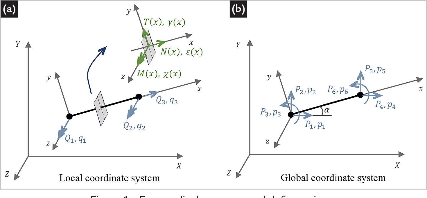
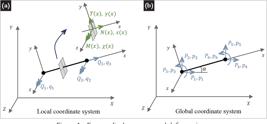
The two-node 2-D beam element can be described in both local and global coordinate systems, as shown in Figure 1. In the local coordinate system, the element is characterized by three displacement degrees of freedom qi, comprising two rotational components and one axial component, along with their corresponding nodal forces Qi. In the global coordinate system, the element is defined by six generalized displacement degrees of freedom pi, with the associated nodal forces Pi. These nodal quantities can be conveniently assembled into vector form as
The nodal displacement and force vectors can be transformed between the local and global coordinate systems according to
where R denotes the rotation matrix and B represents the kinematic transformation matrix, given as
2.2 Section deformations and forces
At a given cross-section along the reference local axis x, deformation and force resultants are assembled into vectors as
where ε0 is the axial strain due to the axial force N, γ is the shear distortion due to the shear force T, and χ is the curvature due to the bending moment M. Force resultants can be interpolated from nodal force values as
in which b(x) corresponds to the interpolation functions for a linear variation of the bending moment along the element and a constant axial force. The explicit definition of the interpolation functions for displacements is not required, as they vanish from the governing equations (Spacone et al., 1996a).
The force-deformation relationship at a cross-section can be expressed as
in which f(x) denotes the cross-section flexibility matrix, defined as the inverse of the corresponding stiffness matrix k(x). Under linear elastic behavior and assuming a constant cross-section along the element length, the flexibility matrix remains constant. For non-linear constitutive behavior, f(x) becomes a function of the deformations d(x). In the force-based finite element formulation, this constitutive relationship is enforced, within a prescribed tolerance, at a set of control cross-sections. Along the element, this relationship is satisfied in a weighted integral form.
2.3 Governing equations
The governing equations of the problem in the local coordinate system are obtained by taking the weighted integral form of Eq. (6) along the element and by applying the principle of virtual displacements to derive a beam equilibrium relation, leading to
where F is the flexibility matrix of the element given by
The element flexibility matrix F is evaluated through numerical integration, in which f(x) is evaluated at the cross-sections located at the integration points, corresponding to control sections where the force-deformation relationship is satisfied.
The governing equation can be rewritten in terms of quantities in the global coordinate system by applying the transformation relations in Eq. 2, leading to
where K is the element stiffness matrix.
With the definition of the stiffness matrix K, the force-based element can be implemented in displacement-based finite element codes. The global numerical solution of the structure is performed using the conventional Newton-Raphson method, in which the applied loads are divided into load steps, each consisting of iterations i. For each iteration i of the Newton-Raphson solution scheme, an iterative resolution procedure is applied to determine the element state (updating F) and the control cross-sections (updating f) located at the integration points. Spacone et al. (1996a) proposed an algorithm for this non-linear solution procedure, which is described in detail in Taucer et al. (1991).
3. Macro-element for masonry shear walls
The force-based beam element formulation was specialized for the analysis of unreinforced masonry shear panels by Addessi et al. (2014), who adopted a non-linear uniaxial constitutive model with no tensile strength for the masonry and incorporated a non-linear shear hinge to simulate failure due to bed joint sliding and diagonal cracking. The stiffness matrix is evaluated at the cross-sections by exact analytical integration, achieved by subdividing the cross-sections into parts. In what follows, the formulation is extended to account for the tensile strength of masonry and steel reinforcement. In addition, modifications were introduced in the matrix representation of the cross-section force-deformation relationship, resulting in a more robust numerical scheme with improved convergence.
3.1 Constitutive models for masonry, reinforcement and the shear hinge
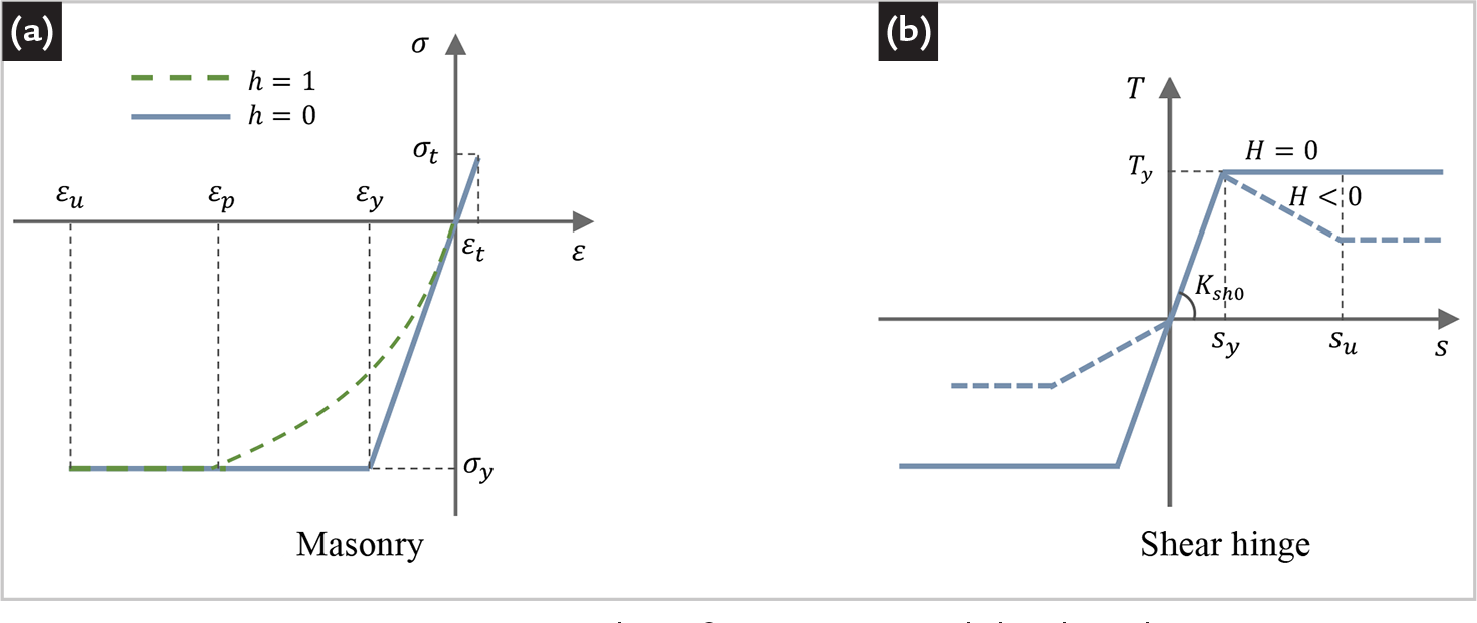
For masonry, the constitutive relationship adopted for a compressive normal stress acting on the panel cross-section follows the expressions introduced by Grande et al. (2011). In the present study, an additional linear elastic branch is incorporated to represent normal stress in the tensile regime, leading to
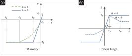
being σ the normal stress, τ the shear stress, E the Young’s modulus, and G the shear modulus. In tension, the limiting strain εt corresponds to the tensile strength σt. Shear stress vanishes under traction. In compression, the normal stress distribution depends on the value adopted for the parameter h, which may vary between 0 and 1. The strain parameter εp must be determined to ensure continuity between the stress-strain curves. For h = 0, it follows that εp = εy, and the constitutive relationship reduces to a perfect elastoplastic model. For h = 1, it follows that εp = 2εy, and the stress-strain curve is non-linear from the onset of compression. The stress σy represents the compressive strength of masonry, and εy is the corresponding normal strain in the linear regime, defined as εy = σy /E. Consequently, for h ≠ 1, the point (σy, εy) does not lie on the stress-strain curve. Figure 2-a shows the normal stress-strain curve adopted for masonry. It is worth noting that this relationship can be adapted, through homogenization techniques and an appropriate definition of the material parameters, to reproduce the behavior of more complex materials such as fiber reinforced composites.
For steel, perfect elastoplastic behavior is assumed for the normal stress acting on the cross-section of the bars, both in tension and in compression, i.e.,
where Eb is the Young’s modulus, σyb is the yield stress, and εyb is the corresponding normal strain.
Shear failure due to slipping of horizontal bed joints or diagonal cracking is modeled using a non-linear shear hinge in the context of lumped plasticity, which enriches the displacement field once the shear stress exceeds the shear strength. The constitutive law of the shear hinge relates the shear force T to the lateral displacement s, as illustrated in Figure 2-b, in which Fsh0 = 1/Ksh0 is the initial shear flexibility of the hinge, and H is a softening parameter. The shear hinge exhibits softening behavior for H < 0 and perfect elastoplastic behavior for H = 0. The implementation is carried out in terms of the hinge secant flexibility Fsh.
For application to masonry shear walls, Ty is determined by evaluating which failure mode is more critical: bed joint shear (Ty1) or diagonal cracking (Ty2). For failure due to bed joint shear, only the portion of the cross-section that is under compression is considered to resist the shear stresses; thus, Ty1 can be evaluated as follows:
where t is the cross-section thickness, and B’ is the width of the portion of the cross-section under compression. The shear strength fv can be estimated using the Mohr-Coulomb criterion (Magenes and Calvi, 1997), where σn is pre-compression normal stress, c is the bed joint cohesion, μ is the bed joint friction coefficient, and fvLIM is the limiting shear strength.
The Turnšek and Cacović criterion (Turnšek and Cacović, 1970) is, in turn, adopted to evaluate the shear strength under diagonal cracking,
where B is the cross-section width, and ftd is the masonry tensile strength for diagonal cracking. Alternatively, the criteria proposed by Mann and Müller (1982) may be adopted in the case of diagonal cracking through joint failure mode.
The contribution of the shear hinge is incorporated into the element flexibility matrix F, in the local coordinate system. For a constant shear force T in the element (Eq. 5) and a hinge rotation qsh = s/L, assuming small displacements, the resulting contribution is given as
It should be noted that the typical response of shear panels in a pushover analysis may exhibit a hardening behavior prior to reaching the maximum load capacity, followed by a softening response (Calderini et al., 2009). In this context, a more realistic shear hinge law comprises both hardening and softening branches, defined according to strength estimates associated with bed joint shear failure and diagonal cracking. Moreover, a damage criterion that accounts for stiffness degradation upon cracking should be considered if the panel undergoes unloading. The force-drift relationship can be established based on analytical approximations, experimental evidence, or requirements from technical standards. The reader is referred to the articles by Rinaldin et al. (2016), Quagliarini et al. (2017), Peruch et al. (2019b), and Camata et al. (2022) for more advanced non-linear shear hinge formulations.
The contributions of the masonry and the steel reinforcement are incorporated through the section stiffness matrix k, as described below.
3.2 Section stiffness matrix
The coefficients of the section stiffness matrix k can be derived by integrating the stress components along the cross-section to obtain a force-deformation relationship,
where the stress-strain relation is given by Eqs. 10 and 11, and the normal strain varies linearly along the cross-section,
For the rectangular masonry cross-section, the area Ael(x) is conveniently decomposed into regions defined by the distribution of normal strain along the y-axis. Since the normal stress vanishes for ε > εt and ε < εu, the integrals in Eq. 13 are evaluated over Ael = At ∪ Ae ∪ Ai, in which At(x), Ae(x), and Ai(x) correspond to the regions where 0 < ε ≤ εt, εp < ε ≤ 0, and εu < ε ≤ εp, respectively.
By evaluating the integrals in Eq. 12 and rearranging the terms, the contribution of the masonry to the section stiffness matrix is obtained as
in which Sk(x), Ik(x), and Jk(x) refer to the first, second and third moments of the area Ak, respectively, and κ is the shear correction factor. It is important to note that, depending on the deformation values d, some geometric properties may vanish, leading to a nonzero singular stiffness matrix k. Furthermore, it is assumed that, for nonzero values of Ai and Si, the strain values of ε0 and χ are also nonzero.
The contribution of the steel reinforcement to the section stiffness matrix is evaluated using a fiber-based approach, in which the normal strain εb, measured at the centroid of each reinforcing bar, is assumed to be constant, resulting in
where Aes, Ses and Ies refer to the summation of the geometric properties of all bars in the linear elastic regime, while Ais and Sis refer to the summation of the geometric properties of all bars in the plastic regime. The shear stiffness of the reinforcement bars is neglected.
Although the examples presented in the following section consider rectangular cross-sections, the formulation can be applied to arbitrary cross-section shapes under the assumption of a plane problem, provided that the geometric properties Ak(x), Sk(x), Ik(x), and Jk(x) are supplied.
In the original formulation by Addessi et al. (2014), the force-deformation relation expressed in Eq. 12 was rewritten as
This modification ensured a nonsingular section stiffness matrix k(x) for a k ≠ 0, thereby allowing the evaluation of the section flexibility matrix f(x) through direct matrix inversion. In that formulation, the force vector Sl(x) was transformed into an equivalent nodal displacement vector, which introduced an additional term dependent on the solution d into the load vector P in Eq. 9. As a consequence, in the Newton-Raphson iterative scheme, the Jacobian matrix of the residual force did not coincide with the element stiffness matrix K. Nevertheless, the solution procedure adopted in Addessi et al. (2014) employs the matrix K as the Jacobian matrix in the iterative scheme, thereby losing quadratic convergence. Despite this limitation, the method is still able to obtain solutions for non-linear problems due to the tensile failure of the panel.
With the extension of the formulation to reinforced masonry panels, it was observed that, in several cases involving reinforcement yielding or compressive plasticity of the masonry, the convergence of the numerical solution deteriorates significantly and, in many instances, cannot be achieved, even when a large number of iterations is employed. Therefore, in order to preserve a formulation that can be readily implemented within an existing finite element code, while ensuring that the Jacobian matrix remains coincident with the matrix , the present study adopts the force-deformation relationship (Eq. 12) as originally proposed by Spacone et al. (1996a). As a consequence, it was necessary to identify and classify the different cases of singularity of the section stiffness matrix k(x) in order to obtain the section flexibility matrix f(x), as discussed in the following section.
3.3 Section flexibility matrix
In the numerical integration of the element flexibility matrix F (Eq. 8), the section flexibility matrix f must be evaluated at the integration points, based on the section stiffness matrix k, which may be singular depending on the values of the geometric properties of the cross-section. This issue has been reported in the force-based formulation and may lead to convergence failure during the iterative solution process (Feng et al., 2023). Nevertheless, for cases in which k ≠ 0, the singularity of the stiffness matrix k does not imply the nonexistence of the flexibility matrix f; rather, it only makes its direct evaluation by simple matrix inversion impossible.
As the section stiffness matrix k is defined in the local coordinate system and does not account for rigid body motions, its singularity can be associated with inadmissible deformations, which are represented by the basis of inadmissible strain modes W. The orthogonal projectors onto the spaces of inadmissible and admissible deformations, PW and PW⊥, respectively, can then be defined as
Thus, the flexibility matrix f can be obtained using the generalized Bott-Duffin inverse (Ben-Israel and Greville, 2003) of the stiffness matrix k, constrained to the space of admissible deformations, as
Table 1 presents the cases in which the stiffness matrix k is singular and indicates the basis of inadmissible deformations W to be employed in Eq. 18.
3.4 Numerical integration and solution scheme
The integrals evaluated along the element length, such as the integral used to obtain the element flexibility matrix F, given by Eq. (8), are computed numerically using integration quadrature schemes. Although Gauss-Legendre quadrature requires fewer integration points to evaluate a given polynomial, the internal location of its integration points is, in most cases, distant from the critical sections of the panel, where masonry tensile cracks or steel reinforcement yielding occur, that is, regions associated with significant variations in the section flexibility matrix f. Consequently, for this type of application, Gauss-Lobatto quadrature is commonly adopted, as it includes the element nodes among the integration points. For an element with linear elastic material, two integration points are sufficient when using Gauss-Legendre quadrature, whereas four integration points are required when using Gauss-Lobatto quadrature to integrate the flexibility matrix accurately. For the non-linear constitutive model adopted in the present study, a larger number of integration points is required.
The iterative scheme for the numerical solution of a structure within the context of a displacement formulation using the Newton-Raphson method is described in detail by Taucer et al. (1991). For each load step, iterations i are carried out until the residual force is reduced to zero, that is, until equilibrium between the external and internal forces is attained. For each iteration i, the structural stiffness matrix , the internal force vector and the associated correction to the displacement increment are computed.
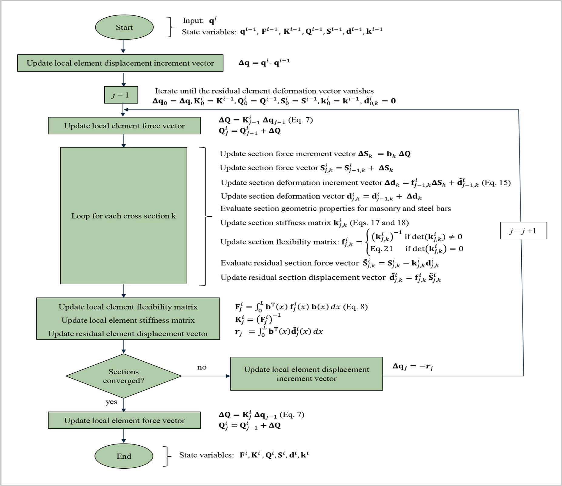
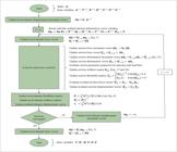
For each iteration i, based on the computed displacement increment Δq, the element state (Q, q) and the control section states (S, d) are determined through an independent iterative scheme with iterations j, in order to evaluate the updated structural stiffness matrix and the internal force vector. For each iteration j, the matrices f(x) and F are updated, and convergence is achieved when the element force-displacement relation (Eq. 7) and the section force-deformation relation (Eq. 6) are satisfied within a predefined tolerance.
Addessi et al. (2014) employed only one iteration in the j-loop, achieving convergence in the determination of the element state (Q, q) and the control sections states (S, d) through convergence of the Newton-Raphson i-loop. This solution scheme may be advantageous, since it leads to a smaller total number of iterations in problems exhibiting mild nonlinearity. However, for several cases involving reinforcement yielding or compressive plasticity of the masonry, convergence of the numerical solution cannot be achieved, even when a large number of iterations is employed. In this sense, the present work adopts the iterative procedure described by Taucer et al. (1991), thereby satisfying Eqs. (6) and (7) at each Newton-Raphson iteration.
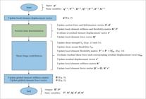
The state of the shear hinge is determined at the end of the j-loop, corresponding to a converged element state and converged control section states. The residual displacement of the hinge is transferred to the internal force vector of the Newton-Raphson iteration and tends to zero as convergence is achieved. Figures 3 and 4 show the flowcharts for the determination of the element state and the section state, respectively.
4. Numerical applications
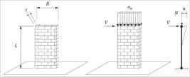
The computational implementation of the formulation was carried out using the mathematical computing software GNU Octave (2025). In the following applications, clamped-free masonry panels were simulated using a single force-based macro-element, and the results were compared with experimental data and those obtained from more refined numerical models.
As discussed in Cattari et al. (2022), a calibration process is generally required to achieve a consistent cross-comparison between refined models and unidimensional beam-like models. Therefore, results should be interpreted with caution, taking into account not only the limitations inherent to the respective formulations but also the availability and quality of the input data.
It should be noted that, in the force-based simulations, the material parameters obtained from experimental programs on prisms, masonry wallets, and panels were adopted as input data whenever available. These parameters include masonry stiffness (Young’s modulus and Poisson’s ratio), as well as the compressive and tensile strengths of the masonry, and the cohesion and friction coefficients of the bed joints. For both applications in this section, the masonry tensile strength associated with diagonal cracking was not determined in the experimental characterization program and was therefore calibrated against the experimental panel results. Similarly, the ultimate masonry strain, as well as the drift capacity and the softening parameter of the shear hinge, were also calibrated in order to achieve a more accurate reproduction of the panel response.
Refined models, such as those based on continuum 2D and 3D micro-modeling approaches within a finite element framework, require deformation and strength parameters for both units and mortar joints. The stiffness parameters of the interface joints, particularly the normal stiffness in tension, may vary significantly in experimental characterization tests. Therefore, it is common practice to calibrate the stiffness parameters of the interface joints against experimental panel results in order to match the initial stiffness of the load-displacement curve. To describe the degradation of stiffness and strength, damage parameters, such as fracture energies must be considered. These parameters are typically estimated from experimental tests and subsequently calibrated against panel test results.
On the other hand, simulations in engineering practice typically adopt models based on a beam-like approach, in which the shear hinge parameters (shear strength, ultimate drift, and softening parameter), and, when applicable, the moment hinge parameters, are derived from standard design codes. These codes provide estimates of maximum strength (in terms of bending, shear, and axial forces) and limiting drift values based on both analytical and experimental evidence (Cattari et al., 2022).
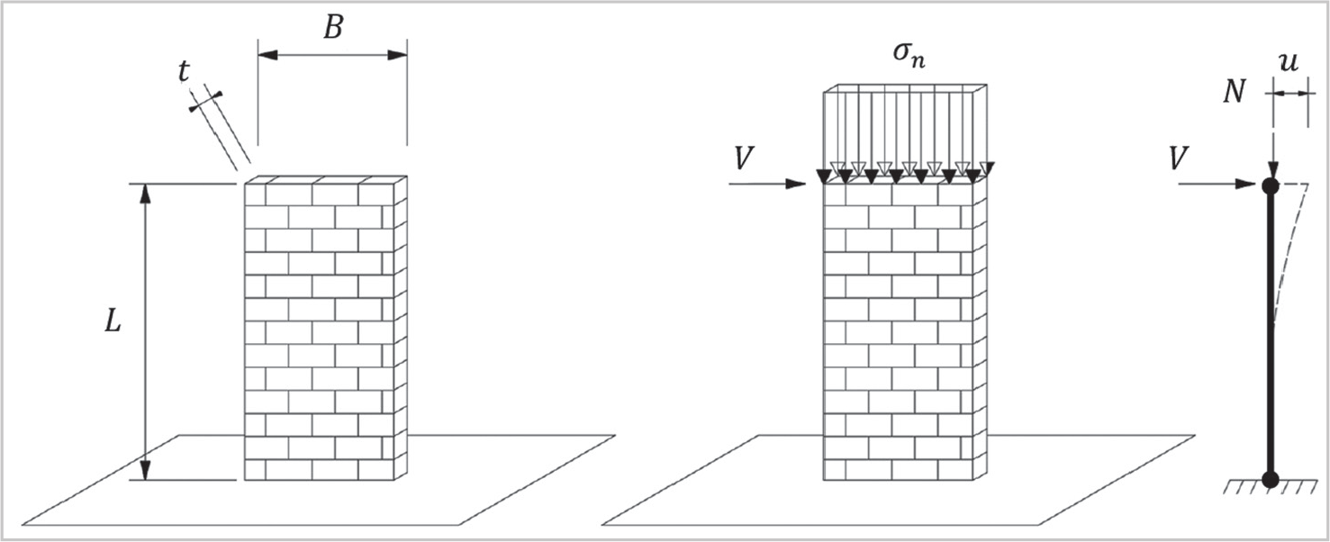
In the following applications, each clamped-free shear masonry panel was discretized using a single macro-element, as depicted in Figure 5, with 5 integration points. The pre-compression load σn was applied in 10 load steps, followed by a prescribed displacement incrementally applied in 50 load steps at the top of the panel, from which a lateral force V was computed as a reaction force. In the Newton-Raphson iterative scheme and in the iterative procedure for determining the element and section states, a force error tolerance of 0.01% was adopted, with a maximum of 50 iterations.
4.1 Example 1
An unreinforced shear masonry panel with dry vertical joints, a height of 0.8 m, and a width of 1.206 m, subjected to a pre-compression stress of 0.56 MPa, was experimentally tested under cyclic lateral loading by Haach et al. (2010) and Haach et al. (2011). The panel exhibited failure due to diagonal cracking and was numerically simulated by Haach et al. (2011) using a two-dimensional non-linear solid finite element model based on the simplified micro-modeling approach under monotonic loading.
Haach et al. (2011) employed a two-dimensional non-linear solid finite element model using the software DIANA® to simulate the panel through a simplified micro-modeling approach, in which masonry units and joints were represented separately. Concrete masonry units were modeled using solid elements under a Total Strain Crack Model, with the Young’s modulus, Poisson’s ratio, tensile and compressive strengths, and fracture energies adopted as input parameters. Mortar joints were modeled using interface elements governed by a plastic cap model with frictional and damage behavior, capable of simulating failure mechanisms due to tension, frictional slip, and crushing. This model requires the specification of normal and tangential stiffness parameters, cohesion and friction angle, tensile and compressive strengths, and fracture energies. For the mortar interface, the tensile fracture energy and the shear contribution to failure were defined by fitting the numerical results to the experimental data (Haach et al., 2011).
The present study, on the other hand, employs a single macro-element to simulate the entire shear panel. The total length of the element was extended to the centroid of the top and bottom beams, resulting in a final length of 1.08 m. Table 2 presents the geometric and material properties used as input data in the simulation. For the masonry, h = 1 was adopted in the material constitutive law. It should be noted that both numerical analyses-Haach et al. (2011) and the present study-aim to reproduce the backbone curve of a cyclic experiment through a monotonic pushover analysis, which requires parameter calibration. In the present analysis, the softening parameter H = 0 of the shear hinge was calibrated based on the post-diagonal cracking response of the experimental curve.
Moreover, the panel behavior deviates significantly from isotropic behavior due to the presence of dry vertical joints. Haach (2009) observed that the Young’s modulus E obtained from the panel test did not correspond to the value obtained from the axial compression test of the masonry wallets, and therefore adopted, in the numerical modeling, the Young’s modulus derived from the panel test. For this reason, as a modeling attempt in the present study, the shear modulus G was also calibrated against the experimental load capacity curve of the panel, replacing the value obtained from the diagonal compression test of the masonry wallet. It is observed that the calibrated value corresponds to a Poisson’s ratio outside the theoretical bounds for a linear elastic material.
The diagonal tensile strength was not estimated in the experimental material characterization and was therefore calibrated in this study in order to reproduce shear failure due to diagonal tension at a lateral load of 32.76 kN, as observed in the experimental test. The obtained value of ftd = 0.11 MPa is consistent, since for any inclined direction, there are portions of dry vertical joints that do not contribute to the tensile strength, resulting in values lower than the tensile strength perpendicular to the bed joints.
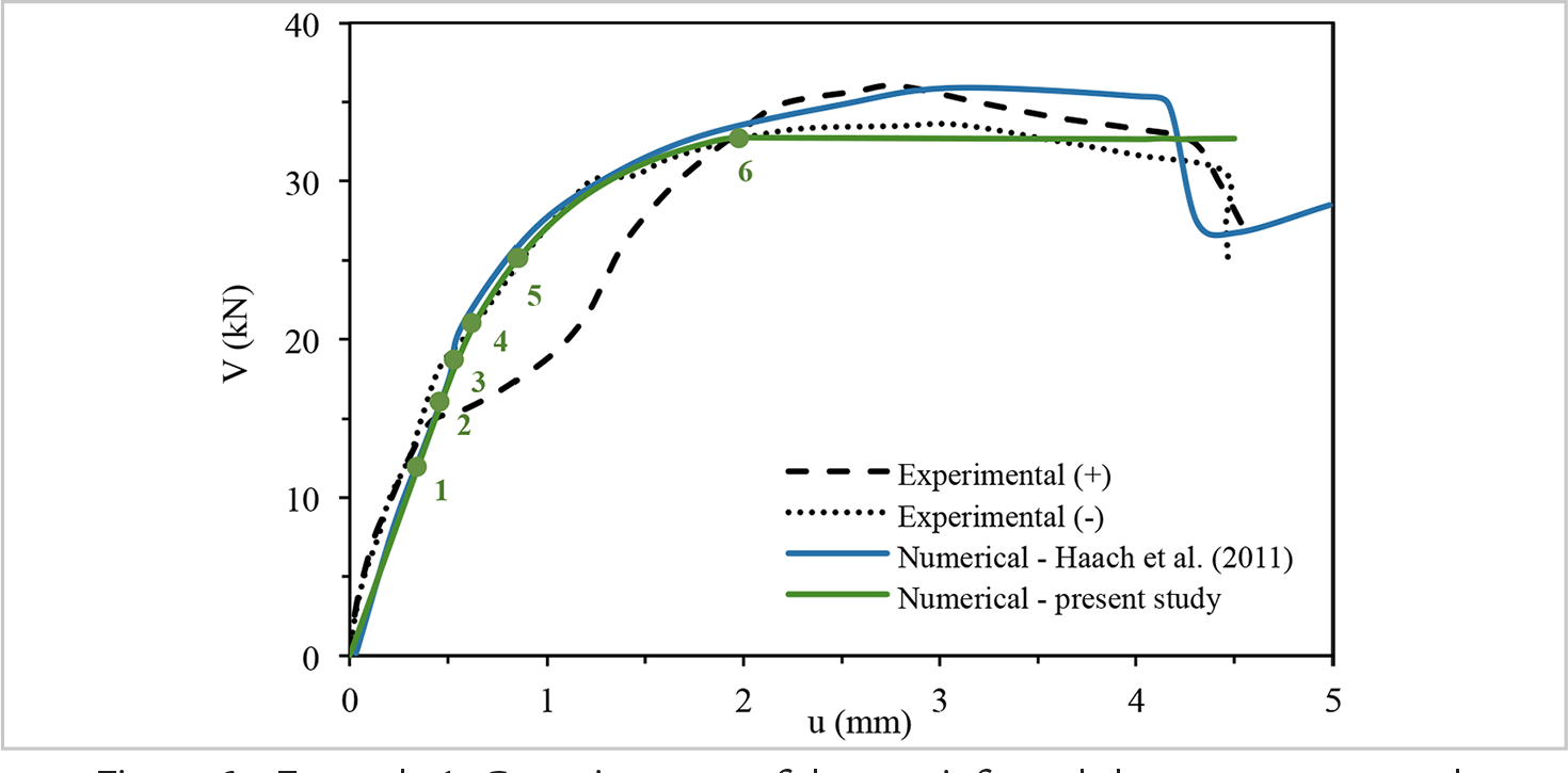
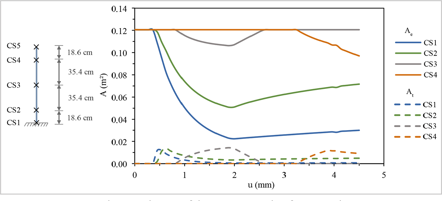
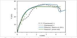
Figure 6 presents the experimental and numerical results for the capacity curve. The experimental results (+) and (-) correspond to the backbone curves of the lateral force-displacement response obtained from the applied positive and negative displacements at the top of each side of the panel, according to the imposed displacement-time history. Both the numerical results from Haach et al. (2011) and those from the present study were obtained under monotonic loading. Figure 7 shows the evolution of the areas At and Ae for control sections 1 to 4 in the element.
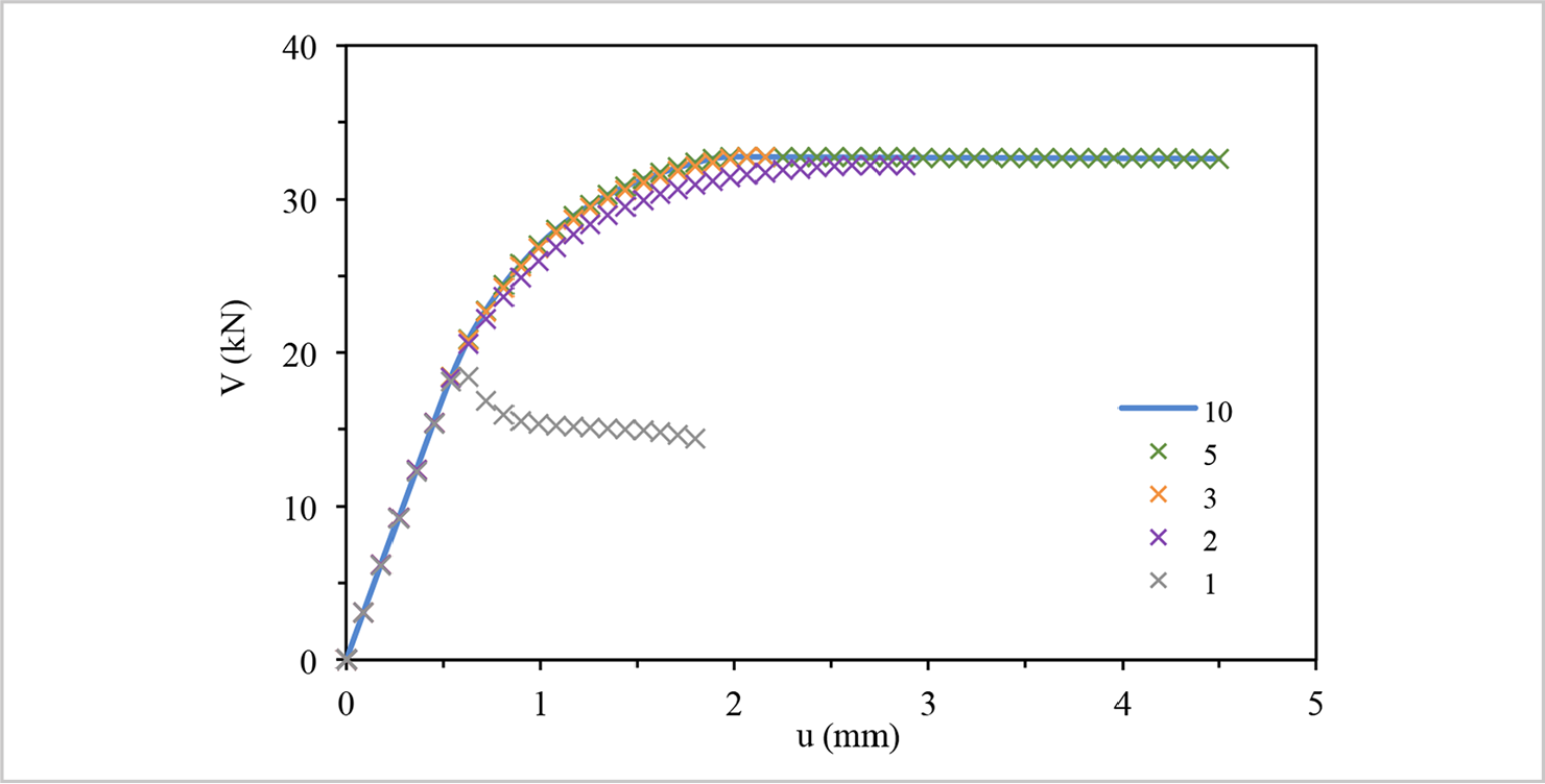
Example 1: Capacity curve for different iteration limits of j in the determination of the element and section states.
All control sections are initially within the linear compressive regime due to the applied pre-compression load. At points 1, 2, and 5, tensile stresses develop at control sections 1, 2, and 3, respectively. It is observed that the limit of the linear branch in the numerical analysis occurs at point 3 (0.54 mm, 18.40 kN), which is in good agreement with the experimental value (0.48 mm, 15.33 kN). From this point onward, the total effective area Ae + At + Ai begins to decrease due to tensile cracking at control section 1, which is the most critical section in the analysis. Control section 4 starts to experience a reduction in total effective area at point 4. Control section 5 is the only one that remains under compression and within the linear elastic regime throughout the analysis. The area Ai remains zero over the entire analysis, indicating that the stresses do not reach the compressive strength of the masonry.
Experimental and numerical results have shown a good agreement up to the onset of diagonal cracking, which was observed in the experimental test at the point (1.97 mm, 32.76 kN). In the numerical result, after activation of the shear hinge at point 6 (1.98 mm, 32.72 kN), a simplified approximation of the curve is observed. The shear hinge law is unable to represent the maximum lateral load of 35.95 kN obtained in the experimental test. According to the experimental results, after the panel experiences failure due to diagonal cracking, the lateral force-displacement curve exhibits a hardening behavior prior to reaching the maximum load capacity, followed by a softening response. This behavior is consistent with the typical behavior of shear panels in a pushover analysis. Therefore, it may be concluded that the shear hinge law adopted in the present study is overly simplified and, consequently, unable to capture the maximum lateral load accurately. Nevertheless, the element exhibits a reasonable overall response, considering that a single element is employed. Moreover, the response shows excellent agreement with the numerical results of Haach et al. (2011) up to the onset of diagonal cracking.
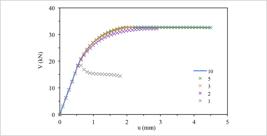
Figure 8 presents the capacity curves obtained for different imposed limits on the number of iterations j used in the determination of the element and section states at each Newton-Raphson iteration i. It can be observed that, for a limit value of j = 3, the analysis is interrupted at 2.16 mm because the number of Newton-Raphson iterations reaches the maximum limit (i = 50). For a limit value of j = 2, the stiffness of the panel is underestimated, and the analysis is interrupted due to rocking failure. Similarly, for a limit value of j = 1, the results deviate from the converged solution at the onset of strength degradation due to tensile stresses at the base of the panel, and the analysis is also interrupted due to rocking failure.
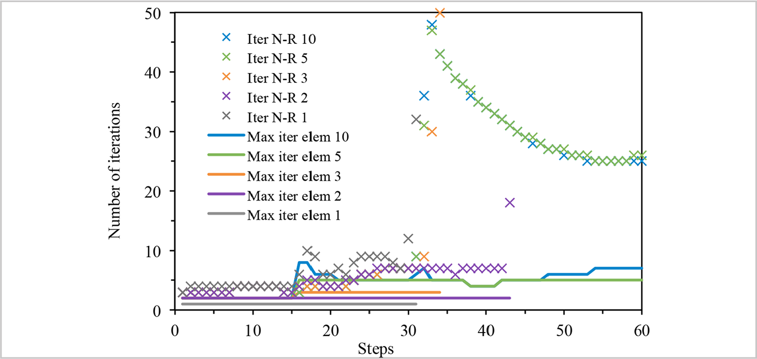
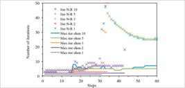
Figure 9 presents the evolution of the number of Newton-Raphson iterations i (represented by lines) and the maximum number of iterations j (represented by cross symbols) for different imposed limits on j in the determination of the element and section states. By monitoring the solution in this example, it is found that 8 iterations are required to evaluate the element and section states within a force error tolerance of 0.01%. For a limit value of j = 3, for instance, a larger number of Newton-Raphson iterations is required, reaching the maximum iteration limit (i = 50) at step 34, at which point the analysis is interrupted. It can also be observed that a limit value of j = 5 leads to satisfactory results.
Example 1: Evolution of the number of Newton-Raphson iterations i and the maximum number of iterations j for different iteration limits in the determination of the element and section states.
4.2 Example 2
An unreinforced shear masonry panel with a height of 88.53 cm and a width of 40.24 cm, subjected to a pre-compression stress of 1.72 MPa, was experimentally tested under monotonic lateral loading by Nascimento Neto (2003). The panel exhibited failure due to flexure and rocking, and was numerically simulated by Nascimento Neto (2003) using a three-dimensional non-linear solid finite element model based on a micro-modeling approach under monotonic loading.
Nascimento Neto (2003) employed a three-dimensional non-linear solid finite element model using the software Abaqus® to simulate the panel through a micro-modeling approach. The interface between the mortar and the units of the first course was represented using contact surface elements. Concrete masonry units were modeled with solid elements based on a concrete constitutive model, requiring as input data the Young’s modulus, Poisson’s ratio, compressive strength, and parameters defining the biaxial behavior. Mortar joints were modeled using solid elements governed by the Mohr-Coulomb plasticity model, requiring the specification of Young’s modulus, Poisson’s ratio, cohesion, and friction angle.
Table 3 presents the geometric and material properties used as input data in the simulation of the present study. The Young’s modulus E, the Poisson’s ratio ν, and the masonry compressive strength σy adopted for the analysis were obtained from the average values of axial compression tests on three masonry wallets. In the numerical analyses, the Poisson’s ratio measured experimentally was used to calculate the shear modulus, resulting in G = 2802 MPa. However, this parameter was also obtained as an average value of G = 1883 MPa from diagonal compression tests on three masonry wallets. The numerical analysis showed little influence on the results.
By calibration, a value of h = 0.4 was adopted for the masonry constitutive model. For h = 0, the panel exhibits rocking failure before reaching the final lateral displacement measured in the experimental result. For h = 1, the capacity curve lies below that obtained for h = 0.4, deviating from the experimental result. The ultimate compressive strain of the masonry was calibrated to match the endpoint of the experimental curve.
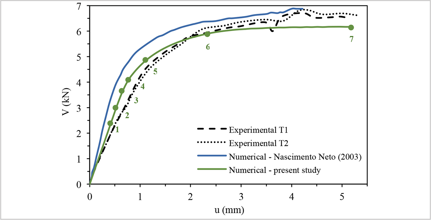
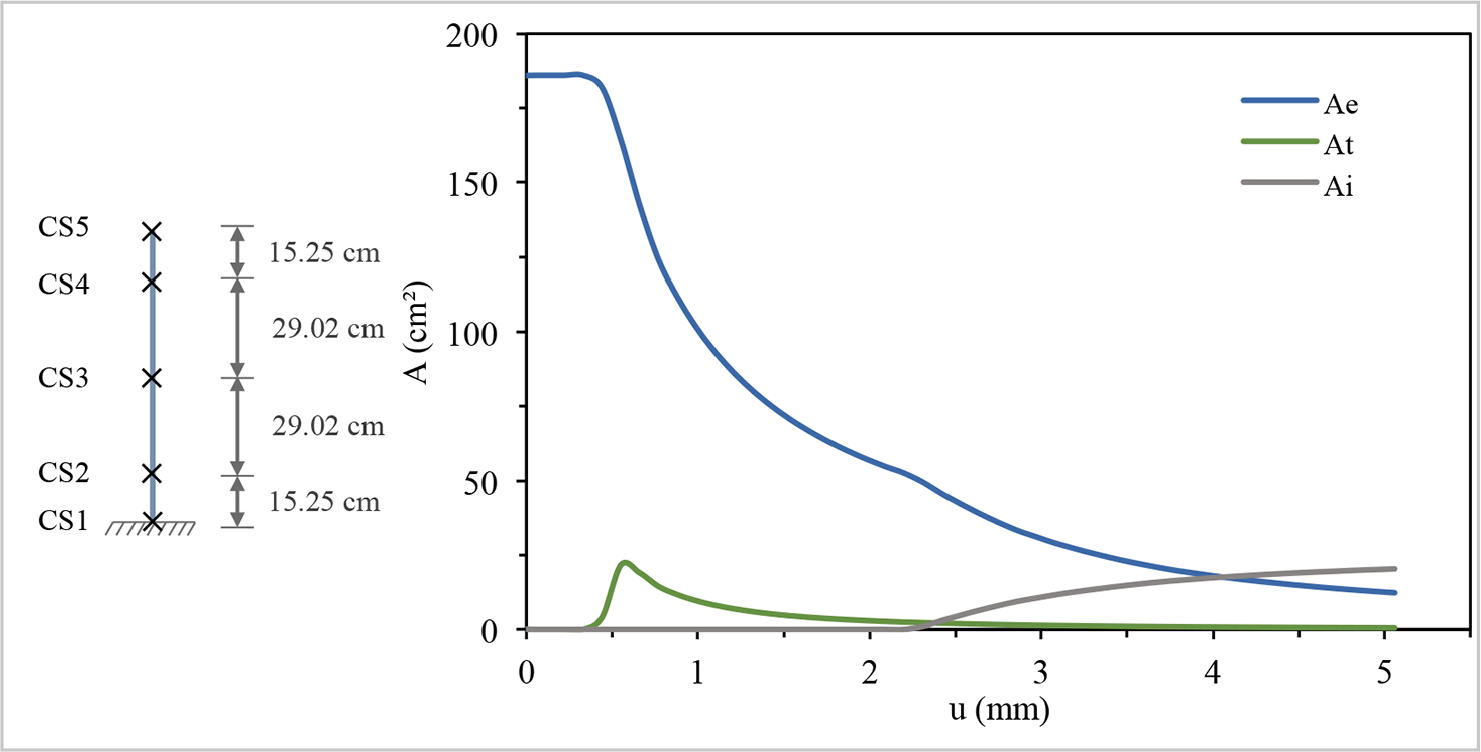
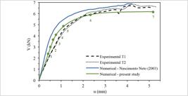
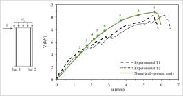
Figure 10 shows the experimental and numerical results for the capacity curves of the unreinforced shear masonry panel. The experimental results were measured at two locations during the test: at the middle of the topmost course of the panel (T1) and at the centroid of the cross-section of the beam, 1.97 cm above the panel (T2). The numerical results are in good agreement with the experimental curves. Figure 11 presents the evolution of the areas Ae, At and Ai for the control section at the base of the panel.
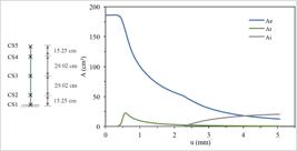
Example 2: Evolution of the areas Ae, At and Ai in the control section at the base of the panel.
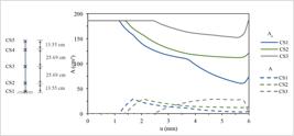
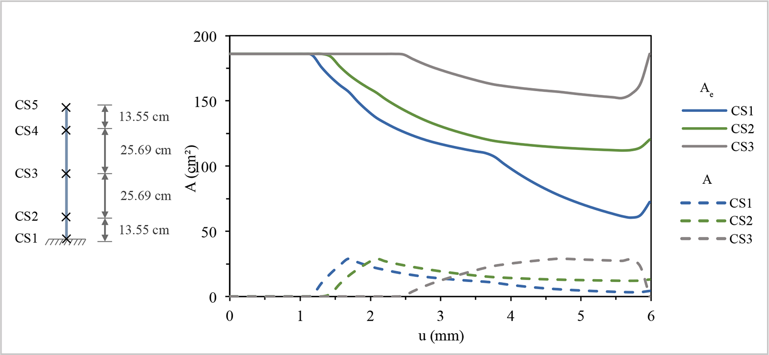
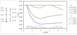
Example 2: Evolution of the areas Ae and At at the control sections 1, 2 and 3 of the reinforced panel.
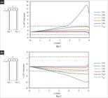
Example 2: Evolution of the normal strain of the reinforcement bars at the control sections.
All control sections are initially within the linear compressive regime due to the applied pre-compression load. At points 1, 2, and 5, tensile stresses develop at control sections 1, 2, and 3, respectively. In the experimental test, Nascimento Neto (2003) noted that between the points (0.70 mm, 3.09 kN) and (1.74 mm, 5.39 kN), despite the absence of visible cracks, audible cracking sounds were heard. In the numerical simulation, the cross-sections at the base begin to lose the total effective area at point 3 (0.66 mm, 3.70 kN), consistent with the observations from the experimental test. Point 4 indicates the onset of tensile stresses at control section 2. The first visible crack in the experimental test occurred at point (1.74 mm, 5.39 kN), close to point 6 (2.31 mm, 5.89 kN) obtained in the numerical result, which marks the beginning of the compressive yielding plateau. Beyond this point, the panel’s load-bearing capacity changes little in the numerical analysis due to the progressive increase of area Ai at control section 1, which indicates the compressive strength of the masonry has been reached. At point 7, the panel fails due to rocking.
In Figure 10, it can be observed that the numerical results reported by Nascimento Neto (2003) exhibit a higher initial stiffness. This behavior can be attributed to the fact that the shear deformability of the mortar joint interfaces was not considered in the model, since the joints were represented by solid elements characterized by the Young’s modulus obtained from mortar compression tests. In the present study, the use of parameters from wallet tests allowed for a more accurate representation of the deformability of the panel. Although the present study provides a better approximation of the initial stiffness, the adopted value of the Young’s modulus from the wallet tests still deviates significantly from the corresponding Young’s modulus of the tested panel, which is 4076 MPa. Even though the maximum load capacity obtained in the present study is lower than the experimental value, the element exhibits a reasonable overall response, considering that a single element is employed.
Nascimento Neto (2003) also tested a reinforced panel with the same characteristics as the unreinforced one, by adding a 5 mm diameter flexure steel bar at each end of the cross-section, positioned 2.44 cm from the edges. In the experimental test, a pre-compression stress of 1.75 MPa was applied, and during the application of the lateral load, the reinforcement cover was observed to detach. The test continued until the panel failed by rocking. It was observed that the panel’s behavior closely resembled that of the unreinforced panel, leading to the conclusion that the reinforcement had not been mobilized during the test. Consequently, the panel was structurally reinforced by grouting from the bottom up to half of the second course, resulting in a height of 78.47 cm. It was assumed that, as most visible cracks occurred at the bottom due to tension and crushing, the panel remained largely intact along its height and could thus be retested. Nevertheless, the reinforced panel exhibited a tensile crack near the base of the fourth course of the initially tested panel. The reinforced panel with grout was tested until failure by diagonal cracking, with no toe crushing observed.
In the numerical simulation of the unreinforced panel, monitoring the effective areas of each control section revealed that the normal stress reached the tensile strength in control sections 1 and 2, located at the base of the panel and at the fifth course, respectively, for a lateral displacement below 1 mm. The control section at the mid-height of the panel exhibited tensile normal stresses below the tensile strength, while the other control sections remained in compression. Despite the grout reinforcement up to half of the second course, the numerical results reveal that the panel underwent a reduction in stiffness due to tensile failure during the initial test. From the analysis of the total effective area, it is estimated that the base of the grout-reinforced panel retained a total effective area equal to 25.4% of the cross-sectional area. Since this section is the most critical, the Young’s modulus of the reinforced panel was set to 25.4% of the original value in the numerical simulation conducted in the present study.
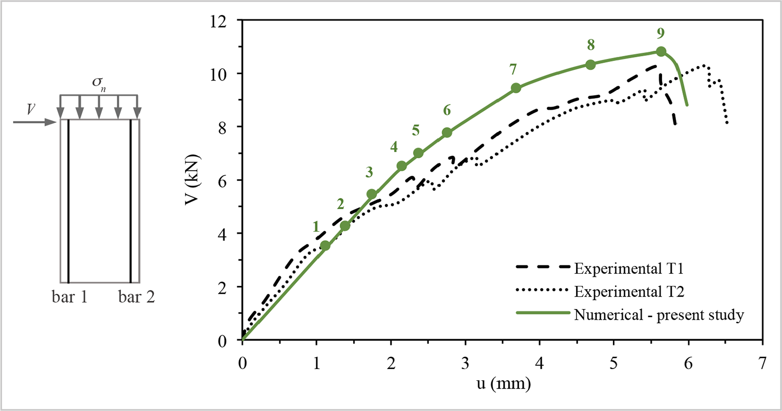
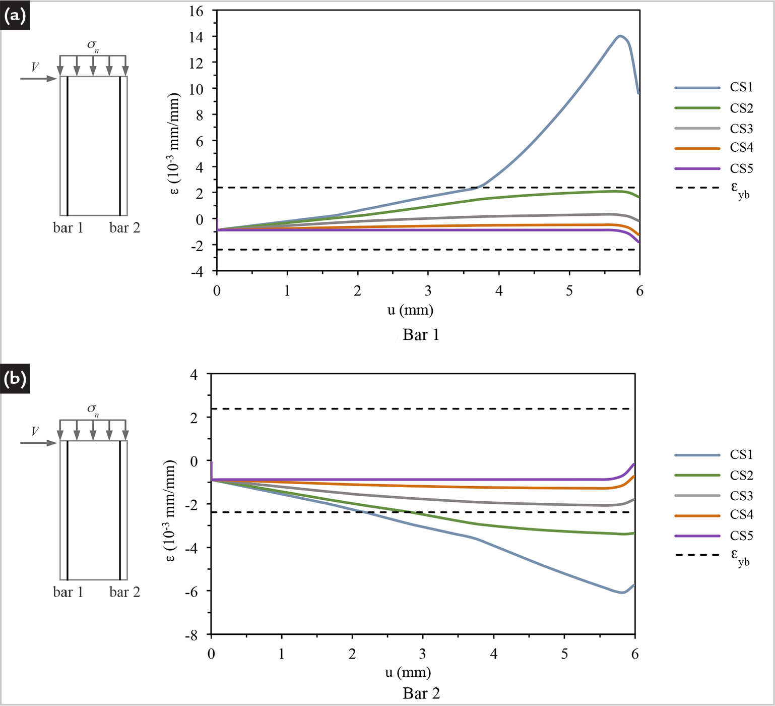
Figure 12 presents the results for the capacity curve of the reinforced shear panel. Figure 13 shows the evolution of the effective areas At and Ae for control sections 1, 2, and 3, and Figure 14 shows the normal strain values for the reinforcement bars 1 and 2.
The diagonal tensile strength of the masonry was calibrated to ftd = 0.36 MPa, with a softening parameter H = 0.15 Fsh0, in order to approximate, on average, point 9 to the endpoints of the two experimental curves corresponding to shear failure due to diagonal cracking. The value of ftd is consistent, since it is close to the value of 0.42 MPa obtained from the average of the diametral compression tests on masonry wallets.
Although the panel ends were grouted due to the flexural reinforcement, for the sake of simplification, the compressive strength of the masonry σy was adopted as the same as the unreinforced panel. In the present study, it can be observed that the initial stiffness of the panel is lower than that obtained from the experimental curve. Even though the contribution of the grout was neglected and the Young’s modulus of the entire panel was adjusted based on the stiffness degradation of the critical sections of an unreinforced panel, the initial stiffness proved to be a reasonable estimate.
It is possible to observe that tensile stresses are developed at control sections 1, 2 and 3 at points 1, 2 and 5, respectively. Control sections 1, 2, and 3 begin to lose total effective area at point 3 (1.82 mm; 5.57 kN), point 4 (2.21 mm; 6.59 kN), and point 8 (4.81 mm; 10.42 kN), respectively, corresponding to stiffness degradation points on the lateral capacity curve. Control sections 4 and 5, located in the upper portion of the panel, did not experience any loss of total effective area and remained in the compression regime until the end of the analysis. No section reached the limiting masonry stress σy; therefore, the area Ai remained null throughout the entire simulation. This behavior is consistent with the findings reported by Nascimento Neto (2003), who emphasized that the presence of reinforcement leads to a more uniform stress distribution in the masonry.
The reinforcement bar 1 yields under tension at control section 1 at point 7 (3.77 mm; 9.53 kN), as shown in Figure 14-a. The reinforcement bar 2 yields under compression at control sections 1 and 2 at points 4 (2.21 mm; 6.59 kN) and 6 (2.86 mm; 7.95 kN), respectively, as shown in Figure 14-b. At those points, it is possible to observe the stiffness degradation in the lateral capacity curve. The numerical results exhibit a satisfactory overall response, which could be further improved by incorporating a bond-slip law for the reinforcement, as proposed in Limkatanyiu and Spacone (2002).
5. Concluding remarks
This study investigated a force-based beam element formulation for the non-linear analysis of structural masonry panels using the equivalent frame method. The study was based on the formulation proposed by Addessi et al. (2014), which focuses on the modeling of unreinforced masonry panels through a macro-element based on Timoshenko beam theory. Within this formulation, the distribution of stresses and strains across the element cross-section is treated in a continuous manner, with an analytical determination of the stiffness matrix of the control sections. The present study contributed to the development of the element by introducing adjustments and extensions to the formulation, as well as modifications to the non-linear solution procedure to improve the robustness of the numerical process.
For masonry, a linear elastic branch limited by a tensile strength was incorporated into the constitutive law. The tensile strength influences the lateral capacity curve of slender unreinforced panels, whose failure is predominantly governed by flexural-compressive mechanisms and rocking. Reinforcement was incorporated through a fiber-based approach. For simplicity, a perfect bond between the reinforcement bars, grout, and masonry units was assumed. The formulation is able to reproduce the stiffness degradation observed in the lateral capacity curve due to reinforcement yielding and cracking of the cross-section in reinforced panels.
Overall, the proposed element reproduces the lateral capacity curves of the analyzed panels with good agreement, and the failure mechanisms associated with flexural-compression and rocking are satisfactorily captured. However, it is believed that a more accurate response could be achieved by adopting an orthotropic constitutive model. Failure modes associated with bed-joint shear and diagonal tension shear, simulated by the non-linear shear hinge, are reproduced approximately, particularly in the softening branch. Alternative shear hinge formulations available in literature, incorporating hardening and softening branches defined from both failure modes, may prove to be more suitable.
Finally, it was verified that an adequate representation of the structural behavior of a shear panel is dependent on the accurate estimation of material properties, encompassing both deformability and strength parameters. In this context, a consistent characterization of material strengths is essential, including not only the uniaxial normal strength at the cross-section level, but also the shear strength along the bed joints and the diagonal tensile strength.
Acknowledgments
The authors gratefully acknowledge the financial support of FAPERJ (Fundação Carlos Chagas Filho de Amparo à Pesquisa do Estado do Rio de Janeiro) - Proc. n. E-26/010.002547/2019 and E-26/010.002150/2019, and CNPq (Conselho Nacional de Desenvolvimento Científico e Tecnológico) - Proc. n. 406617/2023-6 and 402607/2023-6.
-
Funding information
Carlos Chagas Filho Foundation for Research Support of the State of Rio de Janeiro - FAPERJ (Proc. n. E-26/010.002547/2019 and E-26/010.002150/2019) and National Council for Scientific and Technological Development - CNPq (Proc. n. 406617/2023-6 and 402607/2023-6).
Data availability
The authors state that this manuscript is based on the Master's Dissertation of Igor dos Santos Bruno, entitled "Force-based macroelement formulation for the analysis of structural masonry shear walls", presented in 2026 at the State University of Rio de Janeiro (UERJ), in the Postgraduate Program in Civil Engineering (PGECIV), with all data available at the following link: https://www.pgeciv.uerj.br/dissertacoes.
References
- ADDESSI, D.; MASTRANDREA, A.; SACCO, E. An equilibrated macro-element for non-linear analysis of masonry structures. Engineering Structures, v. 70, p. 645-655, 2014.
- ALEMDAR, B. N.; WHITE, D. W. Displacement, flexibility, and mixed beam-column finite element formulations for distributed plasticity analysis. Journal of Structural Engineering, v. 131, p. 1811-1819, 2005.
- AŞIKOĞLUA, A.; VACONCELOS, G.; LOURENÇO, P.; PANTÒ, B. Pushover analysis of unreinforced irregular masonry buildings: lessons from different modeling approaches. Engineering Structures, v. 2018, 110830, 2020.
- AYOUB, A.; FILIPPOU, F. C. Mixed formulation of bond-slip problems under cyclic loads. Journal of Structural Engineering, v. 125, p. 661-671, 1999.
- BARBATO, M.; CONTE, J. P. Finite element response sensitivity analysis: a comparison between force-based and displacement-based frame element models. Computational Methods in Applied Mechanics and Engineering, v. 194, p. 1479-1512, 2005.
- BEN-ISRAEL, A.; GREVILLE, T. N. E. Generalized inverses: theory and applications. 2. ed. New York: Springer, 2003.
- BRACCHI, S.; ROTA, M.; PENNA, A. Comparison of refined and code-compliant modelling strategies for the seismic analysis of unreinforced masonry buildings. Procedia Structural Integrity, v. 44, p. 442-449, 2023.
- CALDERINI, C.; CATTARI, S.; LAGOMARSINO, S. In-plane strength of unreinforced masonry piers. Earthquake Engineering and Structural Dynamics, v. 38, p. 243-267, 2009.
- CAMATA, G.; MARANO, C.; SEPE, V.; SPACONE, E.; SIANO, R.; PETRACCA, M.; ROCA, P.; PELÀ, L. Validation of non-linear equivalent-frame models for irregular masonry walls, Engineering Structures, v. 253, 113755, 2022.
- CATTARI, S.; CALDERONI, B.; CALIÒ, I.; CAMATA, G.; MIRANDA, S.; MAGENES, G.; MILAINI, G.; SAETTA, A. Non-linear modeling of the seismic response of masonry structures: critical review and open issues towards engineering practice. Bulletin of Earthquake Engineering, v. 20, p. 1939-1997, 2022.
- CATTARI, S.; CAMILLETTI, D.; D’ALTRI, A. M.; LAGOMARSINO, S. On the use of continuum Finite Element and Equivalent Frame models for the seismic assessment of masonry walls. Journal of Building Engineering, v. 43, 102519, 2021.
- CATTARI, S.; D’ALTRI, A. M.; CAMILLETTI, D.; LAGOMARSINO, S. Equivalent frame idealization of walls with irregular openings in masonry buildings. Engineering Structures, v. 256, 114055, 2022.
- COLEMAN, J.; SPACONE, E. Localization issues in force-based frame elements. Journal of Structural Engineering, v. 127, p. 1257-1265, 2001.
- D’ALTRI, A. M.; SARHOSIS, V.; MILANI, G., ROTS, J.; CATTARI, S.; LAGOMARSINO, S.; SACCO, E.; TRALLI, A.; CASTELLAZZI, G.; MIRANDA, S. Modeling strategies for the computational analysis of unreinforced masonry structures: review and classification. Archives of Computational Methods in Engineering, v. 27, p. 1153-1185, 2020.
- FENG, D.-C.; CHEN, X.; MCKENNA, F.; TACIROGLU, E. Consistent nonlocal integral and gradient formulations for force-based Timoshenko elements with material and geometric nonlinearities. Journal of Structural Engineering, v. 149, 04023018, 2023.
- GRANDE, E.; IMBIMBO, M.; SACCO, E. A beam finite element for non-linear analysis of masonry elements with or without fiber-reinforced plastic (FRP) reinforcements. International Journal of Architectural Heritage, v. 5, p. 693-716, 2011.
- HAACH, V. G. Development of a design method for reinforced masonry subjected to in-plane loading based on experimental and numerical analysis. Tese - Universidade do Minho, 2009.
- HAACH, V. G.; VASCONCELOS, G.; LOURENÇO, P. B. Experimental analysis of reinforced concrete block masonry walls subjected to in-plane cyclic loading. Journal of Structural Engineering, v. 136, p. 452-462, 2010.
- HAACH, V. G.; VASCONCELOS, G.; LOURENÇO, P. B. Parametrical study of masonry walls subjected to in-plane loading through numerical modeling. Engineering Structures, v. 33, p. 1377-1389, 2011.
- LAGOMARSINO, S.; PENNA, A.; GALASCO, A.; CATTARI, S. TREMURI program: an equivalent frame model for the non-linear seismic. Engineering Structures, v. 56, p. 1787-1799, 2022.
- LAGOMARSINO, S.; CATTARI, S.; ANGIOLILLI, M.; BRACCHI, S.; ROTA, M.; PENNA, A. Modelling and seismic response analysis of existing URM structures. part 2: archetypes of Italian historical buildings. Journal of Earthquake Engineering, v. 27, p. 1849-1874, 2023.
- LIBERATORE, D.; ADDESSI, D. Strength domains and return algorithm for the lumped plasticity equivalent frame model of masonry structures. Engineering Structures, v. 91, p. 167-181, 2015.
- LIMKATANYU, S.; SPACONE, E. Reinforced concrete frame element with bond interfaces. I: displacement-based, force-based, and mixed formulations. Journal of Structural Engineering, v. 128, p. 346-355, 2002.
- LIMKATANYU, S.; SPACONE, E. Reinforced concrete frame element with bond interfaces. II: state determinations and numerical validation. Journal of Structural Engineering, v. 128, p. 356-364, 2002.
- LI, S.; ZHAI, C.-H.; XIE, L.-L. Evaluation of displacement-based, force-based and plastic hinge elements for structural non-linear static analysis. Advances in Structural Engineering, v. 15, p. 477-488, 2012.
- LUCA, B.; GIOVANNI, R.; MARCO, F.; CLAUDIO, A. Survey on non-linear cyclic responses of unreinforced masonry buildings by means of commercial finite-element codes. Procedia Structural Integrity, v. 44, p. 434-441, 2023.
- MAGENES, G.; CALVI, G. M. In-Plane seismic response of brick masonry walls. Earthquake Engineering and Structural Dynamics, v. 26, p. 1091-1112, 1997.
- MANN, W.; MÜLLER, H. Failure shear-stressed masonry - an enlarged theory, tests and application to shear walls. Proceeding of British Ceramic Society, v. 30, p. 223-235, 1982.
- MANZINI, C. F.; MORANDI, P.; MAGENES, G. SAM II: development and validation of an EF based program for seismic pushover analysis of masonry buildings. Bulletin of Earthquake Engineering, v. 21, p. 6317-6365, 2023.
- MORAN, J. G. P.; OLIVEIRA, I. X.; SHAUER, N.; OLIVEIRA, H. L.; SIQUEIRA, G. H. Comparison of displacement-based and force-based formulations for modeling collapse of infill and bare frames. Journal of Building Engineering, v. 113, 113923, 2025.
- MORANDINI, C.; MALOMO, D.; PENNA, A. Equivalent frame discretisation for URM façades with irregular opening layouts. Bulletin of Earthquake Engineering, v. 20, p. 2589-2618, 2022.
- NASCIMENTO NETO, J. A. Estudo de painéis com abertura constituídos por alvenaria estrutural de blocos. Tese (Doutorado em Estruturas) - Universidade de São Paulo - Escola de Engenharia de São Carlos, 2003.
- PENNA, A.; BRACHI, S.; SALVATORI, C.; MORANDINI, C.; ROTA, M. Extending analysis capabilities of equivalent frame models for masonry structures. In: VACAREANU, R., IONESCU, C. (ed.) Progress in European earthquake engineering and seismology. In: ECEES - EARTH AND ENVIRONMENTAL SCIENCES. Springer, 2022, Proceedings [...]. p. 473-485.
- PENNA, A.; ROTA, M.; BRACCHI, S.; ANGIOLILLI, M.; CATTARI, S.; LAGOMARSINO, S. Modelling and seismic response analysis of existing URM structures. part 1: archetypes of Italian Modern Buildings. Journal of Earthquake Engineering, v. 28, p. 1130-1156, 2024.
- PERUCH, M.; SPACONE, E.; CAMATA, G. Non-linear analysis of masonry structures using fiber section line elements. Earthquake Engineering and Structural Dynamics, v. 48, p. 1345-1364, 2019.
- PERUCH, M.; SPACONE, E.; SHING, P. B. Cyclic analyses of reinforced concrete masonry panels using a force-based frame element. Journal of Structural Engineering, v. 145, 04019063, 2019.
- QUAGLIARINI, E., MARACCHINI, G., CLEMENTI, F. Uses and limits of the Equivalent Frame Model on existing unreinforced masonry buildings for assessing their seismic risk: a review. Journal of Building Engineering, v. 10, p. 166-182, 2017.
- RAKA, E.; SPACONE, E.; SEPE, V.; CAMATA, G. Advanced frame element for seismic analysis of masonry structures: Model formulation and validation. Earthquake Engineering and Structural Dynamics, v. 44, p. 2489-2506, 2015.
- REQUENA-GARCIA-CRUZ, M. V.; CATTARI, S.; BENTO, R.; MORALES-ESTEBAN, A. Comparative study of alternative equivalent frame approaches for the seismic assessment of masonry buildings in OpenSees. Journal of Building Engineering, v. 66, 105877, 2023.
- RINALDIN, G.; AMADIO, C.; MACORINI, L. A macro-model with non-linear springs for seismic analysis of URM buildings. Earthquake Engineering and Structural Dynamics, v. 45, p. 2261-2281, 2016.
- ROCA, P.; MOLINS, C.; MARÍ, A. ASCE. Strength capacity of masonry wall structures by the equivalent frame method. Journal of Structural Engineering, v. 131, p. 1601-1610, 2005.
- SPACONE, E.; CIAMPI, V.;FILIPPOU, F. Mixed formulation of non-linear beam finite element. Computers and Structures, v. 58, p. 71-83, 1996.
- SPACONE, E.; FILIPPOU, F. C.; TAUCER, F. F. Fibre beam-column model for non-linear analysis of R/C frames: Part 1. Formulation. Earthquake Engineering and Structural Dynamics, v. 25, p. 711-725, 1996.
- TAUCER, F.; SPACONE, E.; FILIPPOU, F. A fiber beam-column element for seismic response analysis of reinforced concrete structures. Report, College of Engineering, University of California, 1991.
-
THE OCTAVE PROJECT DEVELOPERS. GNU Octave: manual do usuário. Versão 10.1.0: The Octave Project, 2025. Disponível em: <https://docs.octave.org/interpreter/index.html>. Acesso em: 21 set. 2024.
» https://docs.octave.org/interpreter/index.html - TURNSEK, V.; CACOVIC, F. Some experimental results on the strength of brick masonry walls. In: INTERNATIONAL BRICK MASONRY CONFERENCE, 2, 1970, Stoke on Trent, UK. Proceedings [...].1970. p. 149-156.
Edited by
-
Associate Editor
Diogo Rodrigo Ferreira Ribeiro