
Abstract
The Expander Body pile (EB) is a combination of a cast-in-situ pile method with an inflated, pump-grouted tip. The EB system's pioneering conjunction with the conventional drilling pile technique has improved work load, foundation security, cost reductions and abrupt displacements in lateritic, porous, unsaturated soils. The aim of this article is to analyze settlement estimates of bored piles equipped with the Expander Body System on tropical lateritic soil, using a deformability modulus obtained from laboratory and field tests. The piles were subjected to compression and uplift load tests. In addition, the estimates of the pile settlement are compared with the measured values, and the findings are discussed. The results strongly support that PMT and SPT tests present the optimal ratios between the measured and estimated settlements for both bored piles and bored piles with the Expander Body System. It can also be observed that CPT tests presented reasonable estimates for tensioned piles. Ultimately, it is verified that straightforward elastic models for the settlement assessment of bored piles can be used reliably in practice for piles equipped with the Expander Body System on tropical unsaturated soils.
Key words:
settlement; expander body; bored piles; lateritic soils; load test; displacement
1. Introduction
The pre-planned city of Brasilia, Brazil's capital, was built to support the national government and employees. The Federal District area has also increased in residents and established properties. The campus of the University of Brasília (UnB) is situated within the city of Brasília, in an area, most known as "north wing", due to Brasilia’s airplane shape. This research has been conducted at the UnB foundation and in-situ testing research site. Cunha (2011)CUNHA, R. P. Acquired knowledge on the behavior of deep foundations vertically and horizontally loaded in the soil of Brasília. Soils and Rocks, v. 34, n. 3, p. 177-194, 2011. describes that given the city of Brasilia’s distance from major Brazilian cities with already established foundation practice, design solutions for the region, together with the unique conditions of the local tropical subsoil, must be used solely based on local expertise. Therefore, the collapsible conditions of Brasilia’s "porous clay" has motivated researchers and engineering firms to assess the mechanical behavior of many foundation types subjected to vertical and horizontal loads in the past several decades. Continuous flight auger and bored cast-in-situ concrete piles have been widely adopted in pile foundation engineering design in the city of Brasília by local engineering firms, due to the local tropical subsoil's peculiar conditions (collapsible and lateritic). Most recently, new technologies and procedures have been designed and tested. In this regard, the use of bored cast-in-situ piles equipped with Expander Body Systems in the city of Brasília is a pioneering research theme in Brazil.
The Expander Body System (EB) is a bent steel tube 1.2 m wide and 1 to 2 m long, which is inflated (expanded) by an initial pressure-grouting stage, discharged over a grouting tube located in the rebar as shown in Figure 1. Distinct models enable expansion to a diameter of 400 to 800 mm. Grout pressure and volume are continuously registered during EB expansion. The lateral expansion of the EB induces an EB tube length shortening by almost 0.1 m, displayed as a rising of the EB bottom-tip. This expansion causes a soil decompression beneath the EB, which is compensated by a second grouting stage of the soil at the pile tip (Figure 2). The second grouting stage is discharged to the pile tip over a distinct grout tube inside the grout tube employed for the initial grouting stage (passing the EB inner section). Usually, the maximum grouting pressure beneath the EB is of the same magnitude as the EB expansion during the first grouting phase (Fellenius et al. 2018FELLENIUS, B. H.; MASSARSCH K. R.; TERCEROS M. H.; TERCEROS, M. A. A study of the augmenting effect of equipping piles with an Expander Body. In: INTERNATIONAL CONFERENCE ON DEEP FOUNDATIONS AND GROUND IMPROVEMENT, 1st., 2018, Rome. Proceedings [...]. Rome: DFI-EFFC, 2018. v.1, p. 114-123.; Hussain, et al. 2019HUSSAIN, Y.; HUSSAIN, S. M.; MARTINO, S.; CARDENAS-SOTO, M.; HAMZA., O.; REBOLLEDO, J. F. R.; UAGODA, R.; CARVAJAL, H. M. Typological analysis of slide quakes emitted from landslides: experiments on an expander body pile and Sobradinho landslide (Brasilia, Brazil). REM – International Engineering Journal, v. 72, n. 3, p. 453-460, 2019.).

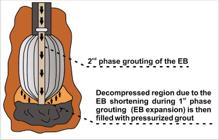
The incipient use of this new technology occurred in activities related to foundation strengthening according to Broms and Nord (1985)BROMS, B. B.; NORD, B. Axial bearing capacity of the expander body pile. Soils and Foundations, v.25, n.2, p. 35-44, 1985., as the building infrastructure in Sweden consisted mostly of wooden piles, which deteriorated over the years due to water table drawdown in the city of Stockholm. The authors also mention that another common application of the Expander Body technology was related to its use in soil retaining structures. The Expander Body developed in Sweden consisted of a bent steel balloon with a square cross-section before its injection and expansion. This square section develops high-stress concentrations at the EB bottom end. In order to mitigate the excessive stress concentration due to the EB geometry developed in Sweden, several versions of the EB have been developed. After multiple prototypes and tests, the model shown in Figure 1 was designed. A post-grouting feature was also added to fill the decompressed region and enhance bonding between the expansive body and the surrounding soil.
Pile settlement is one of the most critical requirements on foundation analysis and design. Pile settlement estimates are usually performed by using elastic models associated with deformability modulus obtained from laboratory and in-situ tests during the design stage. The Expander Body System has been extensively studied with different pile types in Bolivia, which present a predominant sandy subsoil. Terceros and Massarsch (2014)TERCEROS, H. M.; MASSARSCH, K. M. The use of the expander body with cast in-situ piles in sandy soils. In: INTERNATIONAL CONFERENCE ON PILING AND DEEP FOUNDATIONS, 2014, Stockholm. Proceedings [...]. Stockholm: DFI-EFFC, 2014. p. 347-358. evidence that more than 3000 pile foundation elements equipped with Expander Body technology have already been installed in 35 different engineering projects such as bulk silos, industrial facilities, residential buildings and bridges in Bolivia. Many other countries, such as Sweden, Norway, Germany, Japan, Paraguay, Peru, United States of America, South Korea and now Brazil, have implemented this building technology as a viable pile foundation solution. Pile settlement improvement due to the installation of this system in predominantly granular soils has been verified by many researchers (Broms and Nord, 1985BROMS, B. B.; NORD, B. Axial bearing capacity of the expander body pile. Soils and Foundations, v.25, n.2, p. 35-44, 1985.; Fellenius and Terceros, 2014FELLENIUS, B. H.; TERCEROS, M. H. Response to load for four different bored piles. In: INTERNATIONAL CONFERENCE ON PILING AND DEEP FOUNDATIONS, 2014, Stockholm. Proceedings [...]. Stockholm: DFI-EFFC, 2014. p. 99-120.; Terceros and Massarsch, 2014TERCEROS, H. M.; MASSARSCH, K. M. The use of the expander body with cast in-situ piles in sandy soils. In: INTERNATIONAL CONFERENCE ON PILING AND DEEP FOUNDATIONS, 2014, Stockholm. Proceedings [...]. Stockholm: DFI-EFFC, 2014. p. 347-358.; Fellenius et al. 2018FELLENIUS, B. H.; MASSARSCH K. R.; TERCEROS M. H.; TERCEROS, M. A. A study of the augmenting effect of equipping piles with an Expander Body. In: INTERNATIONAL CONFERENCE ON DEEP FOUNDATIONS AND GROUND IMPROVEMENT, 1st., 2018, Rome. Proceedings [...]. Rome: DFI-EFFC, 2018. v.1, p. 114-123.). On the other hand, previous research has failed to address pile settlement improvement (significant abrupt displacements decrease) regarding the installation of Expander Body Systems on bored piles in lateritic and tropical soils, which are the most common soil types in Brazil. This article seeks to evaluate settlement estimates of bored piles equipped with the Expander Body System on tropical lateritic soil, using a deformability modulus obtained from laboratory and field tests.
2. Bored cast-in-situ piles equipped with EB technology installation technique
Diverse methods can be employed to build bored cast-in-situ piles. The principle is essentially the same; there is, however, a slight variation between these approaches. Pile drilling excavation is usually performed utilizing a percussive or rotary method with the use of permanent or temporary casing or drilling mud. Once design depth is reached, the drilling process is ceased. The reinforcement cage is placed, and the borehole is then filled with concrete. The installation procedure of bored cast-in-situ piles equipped with Expander Body technology follows a similar approach. Figure 3 depicts the installation procedure of bored cast-in-situ pile equipped with the Expander Body System. The Expander Body's pre-loading effect decreases specifically required deformations to mobilize toe resistance when compared to traditional bored piles. Load tests indicate that bored piles equipped with EB technology behave similarly to driven piles (Terceros and Massarsch, 2014TERCEROS, H. M.; MASSARSCH, K. M. The use of the expander body with cast in-situ piles in sandy soils. In: INTERNATIONAL CONFERENCE ON PILING AND DEEP FOUNDATIONS, 2014, Stockholm. Proceedings [...]. Stockholm: DFI-EFFC, 2014. p. 347-358.).
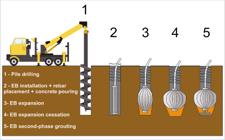
The installation procedure of bored piles equipped with EB technology can be divided into five steps (Figure 3). Initially, pile drilling is carried out. Secondly, the EB is placed at design depth along with the reinforcement bar, and then, concrete is poured into the borehole. The next step consists of an initial grout phase, delivered through a hollow schedule tube (EB expansion). After EB expansion ceases, the second-phase grout step is carried out, so that the decompressed region (pile tip) is filled with pressurized grout. Both injection pressure and volume are continuously monitored using mortar pump and pressure gauge. This equipment not only provides adequate monitoring of the EB expansion but also provides pressure x volume charts. The Expander Body effective diameter (ϕEB) is determined from calibrations curves for each EB model.
3. Materials and methods
The Federal District is limited in the south by the 16°03' parallel and in the north by the 15°30' parallel, presenting a 5814 km2 total area. The UnB geotechnical group's research site has already been thoroughly researched and presented in literature (Cunha et al. 1999CUNHA, R. P.; JARDIM, N. A.; PEREIRA, J. H. F. In situ characterization of a tropical porous clay via dilatometer tests. In: GEO-CONGRESS ON BEHAVIORAL CHARACTERISTICS OF RESIDUAL SOILS, 1st., 1999, Charlotte. Proceedings [...]. Charlotte: ASCE, 1999. v. 1, p. 113-122.; Cunha, 2011CUNHA, R. P. Acquired knowledge on the behavior of deep foundations vertically and horizontally loaded in the soil of Brasília. Soils and Rocks, v. 34, n. 3, p. 177-194, 2011.). Different piling techniques were performed in this research site; besides that, those piles were horizontally and vertically loaded. Moreover, many laboratory and in-situ tests have been carried out on this site. Block samples were collected, transported to the laboratory in order to conduct triaxial, direct shear, oedometer and regular characterization tests. The soil stratigraphy varies between clay, silt, and silty sand in the upper portion of this region. The occurrence of large areas (more than 80% of the Federal District area) covered by a tertiary-quaternary age weathered laterite is typical. This lateritic soil has undergone extensive leaching and presents a variable thickness ranging from a few centimeters to about 40 meters.
An in-situ and laboratory research campaign was conducted at the site to assist the foundation testing program. Standard penetration tests were performed according to ABNT (2001)ASSOCIAÇÃO BRASILEIRA DE NORMAS TÉCNICAS. ABNT NBR 6484: Solo - Sondagens de simples reconhecimentos com SPT - Método de ensaio. Rio de Janeiro: ABNT, 2001. 17 p., using a manual hammer. Cone penetration tests (CPT) were carried out according to ASTM (2007a)AMERICAN SOCIETY FOR TESTING AND MATERIALS. ASTM D4719: Standard test method for pressuremeter testing in soils. West Conshohocken, USA: ASTM, 2007a. 13 p. and Menard pressuremeter tests were conducted according to ASTM (2007b)AMERICAN SOCIETY FOR TESTING AND MATERIALS. ASTM D5778: Standard test method for performing electronic friction cone and piezocone penetration tests of soil. West Conshohocken, USA: ASTM, 2007b. 17 p.. Figure 5 displays a typical stress-strain curve, as well as the fitting approach technique proposed by Fontaine et al. (2005)FONTAINE, E.; CUNHA, R. P.; DAVID, C. A simplified analytical manner to obtain soil parameters from Ménard pressuremeter tests on unsaturated soils. In: PRESSUREMETERS INTERNATIONAL SYMPOSIUM, 5th., 2005, Paris. Proceedings [...]. Paris: LCPC, 2005. v. 1, p. 289-295. for PMT test interpretation. The soil stratigraphy, average SPT blow counts, CPT tip resistance and lateral sleeve friction for each soil layer are depicted in Figure 4. SPT efficiency was not measured during its performance. The simplified soil stratigraphy is characterized by a superficial lateritic layer overtopping a transition zone, and a saprolite originated of the region's native rock.


Previous triaxial tests on block samples were performed at depths of 3 m, 6 m, and 9 m. Initial modulus (Ei) and tangent modulus at 50% of the failure stress (E50) were acquired performing CD tests at cell pressures of 50, 100, and 200 kPa on each depth. A weighted average of these values was adopted according to the stress conditions, obtaining the following values Ei = 7.3 MPa, and E50 = 4.1 MPa. Bored cast-in-situ piles were installed with concrete of a uniaxial strength of about 20 GPa. The test setup adopted for conducting the pile load tests was in accordance with the Brazilian Standard ABNT NBR 12131 (2006)ASSOCIAÇÃO BRASILEIRA DE NORMAS TÉCNICAS. ABNT NBR 12131: Estacas - Prova de carga estática - Método de ensaio. Rio de Janeiro: ABNT, 2006. 8 p.. Static load tests were carried out in ten load stages corresponding to approximately 20% of the pile work load, as shown in Table 1. The load must be maintained at each load stage until the displacement stabilization has occurred and at least for 30 min. Displacement stabilization is attended when the difference between two consecutive readings corresponds to a maximum of 5% at each load stage (ABNT, 2006ASSOCIAÇÃO BRASILEIRA DE NORMAS TÉCNICAS. ABNT NBR 12131: Estacas - Prova de carga estática - Método de ensaio. Rio de Janeiro: ABNT, 2006. 8 p.). The loading stages increased until a distinct plugging failure load was obtained. Seven bored cast-in-situ piles were excavated with a rotating auger at the University of Brasilia experimental site displayed in Figure 4, in which four consist of bored cast-in-situ piles equipped with EB technology and the other three being conventional bored cast-in-situ piles. More details regarding the pile's geometric characteristics are shown in Table 1.
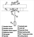
A system comprising reaction beam, reaction piles, hydraulic jack, loading platform and calibrated load cell was adopted in order to apply load. The distance between reaction piles was at least that of three pile diameters. Mechanically bored, cast-in-place piles with and without the Expander Body System were subjected to both compression (Figure 6) and uplift load tests (Figure 7). The Brazilian Standard ABNT NBR 12131 (2006)ASSOCIAÇÃO BRASILEIRA DE NORMAS TÉCNICAS. ABNT NBR 12131: Estacas - Prova de carga estática - Método de ensaio. Rio de Janeiro: ABNT, 2006. 8 p. states that pile load tests can be performed in four different conditions: slow maintained load, quick maintained load, combined load and cyclic load test. In this research, all piles were subjected to slow maintained load tests as shown in Table 1.

Stewart et al. (2011)STEWART, W. P.; CUNHA, R. P.; MOTA, N. M. B. Settlement of floating bored piles in Brasilia porous clay. Soils and Rocks, v. 34, n. 2, p. 153-159, 2011. infer that the sand correlations vary greatly, depending on the sand deposit's stress history and age. The soil dates back to the Tertiary-Quaternary period and is aged. The water table is located beneath the pile embedment depth, and due to differences in the soil suction, the soil is overconsolidated to some extent. Techniques and correlations to obtain E values using in-situ data for each depth are presented in Table 2. The deformability modulus values obtained for each in-situ test were then employed in the Poulos and Davis (1980)POULOS, H. G.; DAVIS, E. H. Pile foundations analysis and design. New York: John Wiley and Sons, 1980. 410p. solution to estimate settlement. It is essential to note the EB expansion gives a pressure-volume curve, similar to the one obtained in a PMT test. The pressure-volume curve represents the soil behavior at the pile toe, in which, a deformability modulus can be obtained from the Expander Body expansion curve (pressure-volume). Poulos (1998)POULOS, H. G. The pile-enhanced raft: an economical foundation system. In: CONGRESSO BRASILEIRO DE MECÂNICA DOS SOLOS E ENGENHARIA GEOTÉCNICA, 11., 1998, Brasília. Proceeding [...]. Brasília: COBRAMSEG, 1998. v. 5, p. 27-43. proposed a correlation between the deformability modulus and NSPT blow counts along and beneath pile toe as 3 NSPT (MPa), where NSPT is the number of blows in an SPT for a 0.3 m displacement. Estimates based on qc values to obtain the deformability modulus vary between 6 to 10 qc, however, Robertson and Campanella (1988)ROBERTSON, P. K.; CAMPANELLA, R. G. Guidelines for using the CPT, CPTU, and Marchetti DMT for geotechnical design. Washington, DC: Federal Highway Administration, 1988. v. 2. (Report No. FHWA PA-87-023+84+24). indicate 8qc as the correlation value, where qc is the cone tip resistance. After standard adjustments, the PMT data was plotted and the curve adjusted using Cunha's (1996)CUNHA, R. P. A new cavity expansion model to simulate selfboring pressuremeter tests in sand. Soils and Rocks, v. 19, n. 1, p. 15-27, 1996. proposed methodology and cavity expansion model. Fontaine et al. (2005)FONTAINE, E.; CUNHA, R. P.; DAVID, C. A simplified analytical manner to obtain soil parameters from Ménard pressuremeter tests on unsaturated soils. In: PRESSUREMETERS INTERNATIONAL SYMPOSIUM, 5th., 2005, Paris. Proceedings [...]. Paris: LCPC, 2005. v. 1, p. 289-295. later modified this original model for cohesive-frictional materials, and this revised version is the model used here. Many soil parameters were thus incorporated into their model and adjusted to match the PMT field curve, obtaining deformability modulus values for each test.
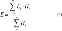
The in-situ tests measurement values (NSPT, qc, Plim) varied with depth, but a weighted average was adopted (the extreme values were neglected). Moreover, a deformability modulus was obtained for each test using the correlations presented in Table 2, as well as using the following equation:
Where: Hi is the ith soil layer thickness; Ei is the ith soil layer deformability modulus.
4. Results and discussions
Seven load tests were carried out in February 2018 (wet season). Table 3 presents the maximum load and displacements recorded during the load tests. The piles were loaded until a plugging failure load was verified. It is worth to mention that the final diameter of the EB model employed in this research is of 0.6 m. The loadsettlement plots are presented in Figure 8. Figure 9 presents the recorded grout volume and pressure during EB expansion and also the second-phase grouting at the pile toe.
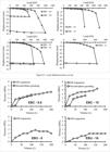
In addition, the deformability modulus values obtained for each in-situ test were then used in the Poulos and Davis (1980)POULOS, H. G.; DAVIS, E. H. Pile foundations analysis and design. New York: John Wiley and Sons, 1980. 410p. solution to predict pile settlement. Pile displacements obtained in load tests were then compared to estimated values. The Poulos and Davis (1980)POULOS, H. G.; DAVIS, E. H. Pile foundations analysis and design. New York: John Wiley and Sons, 1980. 410p. influence factor (I0) is directly affected by the Bb/B ratio, which is the ratio between the pile base diameter (Bb) and the pile shaft diameter (B). In this research, the Bb/B ratio displays a value of about 2 for bored piles equipped with the EB technology, since the expanded EB diameter is around 0,6 m, while pile shaft diameter for compression and uplift piles are 0.3 and 0.25 m, respectively. Therefore, higher Bb/B ratios lead to slightly smaller settlement predictions for any given L/B ratio compared to smaller Bb/B ratios, which is the case of conventional bored cast-in-situ piles (Bb/B ratio = 1). The rigidity factor (K) is also influenced by the pile tip area, which directly impacts soil Poisson's ratio (Rv), pile compressibility (Rk) and tip correction (Rb) coefficients. Higher rigidity factor (K) values result in smaller settlement predictions. Therefore, pile settlement estimates for piles equipped with the EB technology will be lesser than conventional bored cast-in-situ piles. The Poulos and Davis (1980)POULOS, H. G.; DAVIS, E. H. Pile foundations analysis and design. New York: John Wiley and Sons, 1980. 410p. method accounts for the pile stiffness in its rigidity factor (K), as this factor is directly proportional to the pile stiffness (elasticity modulus), therefore, the higher the pile stiffness, the higher is the rigidity factor. A 20 MPa pile stiffness value was obtained in concrete uniaxial compression tests. This pile stiffness value was adopted for all test piles in this research.
Table 4 shows the predicted values to the reference values ratio, as well as the work loads and respective settlements for this load. Settlement ratios for distinct field and laboratory tests are displayed in Figure 10. The employed elastic model allowed a straightforward settlement estimate comparison. PMT and SPT deformability modulus values provide the most suitable pile settlement estimate when analyzing the piles subjected to a compression load. However, for the tensioned piles, the CPT and PMT modulus values present the most exceptional estimates of pile displacements, despite underestimating the displacements of piles EBU – 8 and EBU – 10. The deformability modulus obtained using laboratory (Ei and E50) and EB (using pressure-volume chart) values considerably overestimate pile displacements. In addition, it can be observed that laboratory (Ei and E50) and EB (using pressure-volume chart) pile displacement ratio values significantly diverge from a reasonable settlement estimation zone comprehended by the ±20% margin range. On the other hand, only SPT, CPT, and PMT modulus values result in reasonable pile displacement estimates that fit the ±20% margin range. It is essential to highlight the fact that only settlement ratio values below to five were presented in Figure 10.

The loose debris effect beneath pile base plays a vital role in bored cast-in-situ pile settlement. However, Poulos and Davis (1980)POULOS, H. G.; DAVIS, E. H. Pile foundations analysis and design. New York: John Wiley and Sons, 1980. 410p. do not account for that effect. Nevertheless, this can be one reason that elucidates lower measured displacements in bored cast-in-situ piles equipped with the Expander Body Technology compared to conventional bored cast-in-situ piles in compression load tests, as shown in Figure 8.
Poulos and Davis (1980)POULOS, H. G.; DAVIS, E. H. Pile foundations analysis and design. New York: John Wiley and Sons, 1980. 410p. describe that the base diameter increase leads to greater loads carried by the pile tip and for piles with low L/D values (L/D < 15), base enlargement results in settlement decrease, i.e., is most useful for short piles. The slender the pile (increasing L/D), the greater the load transferred by the pile shaft to the soil, resulting in the pile top settlement decrease i n comparison with the pile movement acting as a single column. Therefore, the Expander Body System installation at low L/D ratios may adversely affect the shaft resistance mobilization in the lower pile segment just above the enlarged base. However, for slender piles (L/D > 20) this effect might become negligible. Since the piles in this research present L/D ratios between 30 and 40, load-settlement behavior and soil deformability modulus values reliability might be hardly affected.
Pile settlement estimates using the deformability modulus obtained from PMT presented the best displacement prediction performance overall when evaluating both compressed and tensioned piles. The PMT and the Expander Body presents significant similarity in their in-situ installation and execution procedure, providing a pressure-volume curve after expansion. This fact might explain the reason that the PMT deformability modulus displayed the best displacement estimates, besides the least soil disturbance when compared to other in-situ tests. The EB expansion monitoring is, in reality, an in-situ soil test, since the EB behaves similar to a pressuremeter (PMT). Therefore, soil conditions (compactness in coarsegrained soils and consistency in fine soils) before EB expansion at the pile toe can be analyzed from the initial portion of the pressure-volume curve. The shape of the curve depends upon the soil's geotechnical conditions (stiffness, strength, and in situ stress).
The SPT is designed to measure soil resistance regarding a standard penetration sampler blow; therefore, it can be speculated that this in-situ test presents limitations in correlations with other properties, such as the soil deformability module. In particular, it is acknowledged that NSPT values are insensitive to soil stress history, while the deformability modulus presents a reasonable sensitivity to a deformation modulus, which can consequently lead to an appreciable dispersion in the relationship between NSPT and deformability modulus (E). Despite this, the SPT correlation with deformability modulus (E) presented acceptable suitability when estimating bored cast-in-situ piles equipped with the Expander Body System displacement in lateritic, porous, unsaturated soils. However, in saturated conditions, especially in saturated clays (low hydraulic conductivity), the neutral pressures generated by the SPT sample insertion in the soil can lead to higher pore-pressure dissipation periods, which can result not only in lower deformability modulus (E) estimates but also in overestimated displacement ratio values for bored cast-in-situ piles equipped with the EB System.
As for the CPT test, a similar trend regarding the neutral pressures generated by the cone penetration velocity rate can be assumed. In contrast, soil disturbance during the CPT test penetration is significantly smaller, when compared to the SPT test, which could lead to more reasonable displacement ratio values.
The load versus displacement curves in Figure 8 points out that conventional bored cast-in-situ piles and bored cast-in-situ piles equipped with EB technology expose similar behavior up to 300 kN (approximately half of conventional bored cast-in-situ piles ultimate load). Subsequently, load versus displacement curves of conventional bored cast-in-situ piles presented abrupt pile-soil displacements (typical of lateritic, porous, unsaturated soils). In contrast, bored cast-in-situ piles equipped with EB system demonstrated larger pile bearing capacity and smaller displacements. For a given displacement magnitude outside the elastic range regarding the load versus displacement curve, bored cast-in-situ piles equipped with EB system yields nearly twice conventional bored cast-in-situ piles bearing capacity when analyzing the same displacement magnitude.
The EB system yields a larger pile load capacity and settlement decrease. It can also be noted that while conventional bored piles were fully mobilized (i.e., continuous displacement increase without load change), conventional bored piles equipped with EB system remained in the elastic range regarding load versus displacement curve, whether considering piles under compression or tension. Therefore, it can be verified that pre-loading influence due to EB expansion reduces necessary deformations to mobilize tip resistance when compared with conventional bored piles. Load tests indicate that bored piles equipped with EB technology behave correspondingly to driven piles.
5. Conclusions
This article emphasized the use of the Expander Body System to improve abrupt displacements observed in lateritic, porous, unsaturated soils, as well as settlement estimate evaluation using field and laboratory tests parameters.
The use of the Expander Body System in conventional bored cast-in-place has presented not only larger bearing pile capacity, but also smaller pile displacements for both compression and uplift loads, demonstrating the potential that this innovative system has for practical use. In fact, this also provides an innovative solution that can be used for foundation design on lateritic and collapsible soils of frequent occurrence in the city of Brasília.
It is also possible to conclude that in the light of all the previous discussion:
1. Despite the limited data, the results strongly illustrate that SPT and PMT tests yield optimal ratios between estimated and measured settlements for piles subjected to compression and uplift loads. It is also worth to note that CPT tests presented a reasonable estimate when analyzing displacements of tensioned piles.
2. In practice, simple elastic models can be used accurately to predict the settlement of bored piles equipped with the Expander Body System on tropical unsaturated soils. In addition, more research prominence must be given on this subject, so that this resourceful technique can turn into a more promptly employed one in practical use.
Acknowledgements
This research was conducted under the tutelage of the Foundation and Field Test Group (GPFees) of the University of Brasilia Geotechnical Post Graduate Program. The first author would like to show his appreciation for the field assistance to the engineering contractor EMBRE and the scholarship granted (GM/GD-140423/2017-6) by the governmental sponsorship organization CNPq (National Council for Scientifc and Technological Development).
References
- AMERICAN SOCIETY FOR TESTING AND MATERIALS. ASTM D4719: Standard test method for pressuremeter testing in soils. West Conshohocken, USA: ASTM, 2007a. 13 p.
- AMERICAN SOCIETY FOR TESTING AND MATERIALS. ASTM D5778: Standard test method for performing electronic friction cone and piezocone penetration tests of soil. West Conshohocken, USA: ASTM, 2007b. 17 p.
- ASSOCIAÇÃO BRASILEIRA DE NORMAS TÉCNICAS. ABNT NBR 6484: Solo - Sondagens de simples reconhecimentos com SPT - Método de ensaio. Rio de Janeiro: ABNT, 2001. 17 p.
- ASSOCIAÇÃO BRASILEIRA DE NORMAS TÉCNICAS. ABNT NBR 12131: Estacas - Prova de carga estática - Método de ensaio. Rio de Janeiro: ABNT, 2006. 8 p.
- BROMS, B. B.; NORD, B. Axial bearing capacity of the expander body pile. Soils and Foundations, v.25, n.2, p. 35-44, 1985.
- CUNHA, R. P. A new cavity expansion model to simulate selfboring pressuremeter tests in sand. Soils and Rocks, v. 19, n. 1, p. 15-27, 1996.
- CUNHA, R. P.; JARDIM, N. A.; PEREIRA, J. H. F. In situ characterization of a tropical porous clay via dilatometer tests. In: GEO-CONGRESS ON BEHAVIORAL CHARACTERISTICS OF RESIDUAL SOILS, 1st., 1999, Charlotte. Proceedings [...]. Charlotte: ASCE, 1999. v. 1, p. 113-122.
- CUNHA, R. P. Acquired knowledge on the behavior of deep foundations vertically and horizontally loaded in the soil of Brasília. Soils and Rocks, v. 34, n. 3, p. 177-194, 2011.
- FELLENIUS, B. H.; TERCEROS, M. H. Response to load for four different bored piles. In: INTERNATIONAL CONFERENCE ON PILING AND DEEP FOUNDATIONS, 2014, Stockholm. Proceedings [...]. Stockholm: DFI-EFFC, 2014. p. 99-120.
- FELLENIUS, B. H.; MASSARSCH K. R.; TERCEROS M. H.; TERCEROS, M. A. A study of the augmenting effect of equipping piles with an Expander Body. In: INTERNATIONAL CONFERENCE ON DEEP FOUNDATIONS AND GROUND IMPROVEMENT, 1st., 2018, Rome. Proceedings [...]. Rome: DFI-EFFC, 2018. v.1, p. 114-123.
- FONTAINE, E.; CUNHA, R. P.; DAVID, C. A simplified analytical manner to obtain soil parameters from Ménard pressuremeter tests on unsaturated soils. In: PRESSUREMETERS INTERNATIONAL SYMPOSIUM, 5th., 2005, Paris. Proceedings [...]. Paris: LCPC, 2005. v. 1, p. 289-295.
- HUSSAIN, Y.; HUSSAIN, S. M.; MARTINO, S.; CARDENAS-SOTO, M.; HAMZA., O.; REBOLLEDO, J. F. R.; UAGODA, R.; CARVAJAL, H. M. Typological analysis of slide quakes emitted from landslides: experiments on an expander body pile and Sobradinho landslide (Brasilia, Brazil). REM – International Engineering Journal, v. 72, n. 3, p. 453-460, 2019.
- POULOS, H. G.; DAVIS, E. H. Pile foundations analysis and design New York: John Wiley and Sons, 1980. 410p.
- POULOS, H. G. The pile-enhanced raft: an economical foundation system. In: CONGRESSO BRASILEIRO DE MECÂNICA DOS SOLOS E ENGENHARIA GEOTÉCNICA, 11., 1998, Brasília. Proceeding [...]. Brasília: COBRAMSEG, 1998. v. 5, p. 27-43.
- ROBERTSON, P. K.; CAMPANELLA, R. G. Guidelines for using the CPT, CPTU, and Marchetti DMT for geotechnical design Washington, DC: Federal Highway Administration, 1988. v. 2. (Report No. FHWA PA-87-023+84+24).
- SADUD, O. A. R.; PINTO, F.; TERCEROS, M. A. H. Efecto de sistemas de desplazamiento en el comportamiento de pilotes perforados en arenas. In: PANAMERICAN CONFERENCE ON SOIL MECHANICS AND GEOTECHNICAL ENGINEERING, 15., 2015, Buenos Aires. Proceedings [...]. Buenos Aires: ISSMGE: ISRM, 2015. v. 2, p. 1544- 1551.
- STEWART, W. P.; CUNHA, R. P.; MOTA, N. M. B. Settlement of floating bored piles in Brasilia porous clay. Soils and Rocks, v. 34, n. 2, p. 153-159, 2011.
- TERCEROS, H. M.; MASSARSCH, K. M. The use of the expander body with cast in-situ piles in sandy soils. In: INTERNATIONAL CONFERENCE ON PILING AND DEEP FOUNDATIONS, 2014, Stockholm. Proceedings [...]. Stockholm: DFI-EFFC, 2014. p. 347-358.
Publication Dates
-
Publication in this collection
21 July 2021 -
Date of issue
Jul-Sep 2021
History
-
Received
14 May 2020 -
Accepted
17 Feb 2021


