Abstract
Steel and concrete floor systems are widely applied for buildings and provide excellent structural response, optimized material consumption, reduced beam height, and improved bending strength and stiffness capacity. In recent years, many experimental investigations concerned with new alternatives addressed to efficient interaction between steel and concrete structures have been reported. In this context, the present study aims at investigating the behavior of a structural composite floor system composed of light cold-formed steel trusses and a partially pre-cast concrete slab, as well as developing an innovative solution for shear connectors. The referred to shear connector consists of Thin-Walled Perfobond (TWP) ribs, composed of 1.25mm thick cold-formed plates crossed by 4.2 mm reinforcing steel bars and connected to the truss chord by self-drilling screws. Preliminary results, based on experimental full-scale testing, indicate that the performance of the composite truss is adequate in terms of ultimate load and deformation capacity. Additionally, the investigation showed that traditional analytical solution is in good agreement with experimental results.
Keywords:
steel and concrete composite floor system; perfobond shear connector; composite trusses; experimental structural analysis
Keywords:
steel and concrete composite floor system; perfobond shear connector; composite trusses; experimental structural analysis
1. Introduction
Steel and concrete composite floor systems are usually applied in several applications in order to guarantee improved structural response, especially in terms of flexural resistance capacity and stiffness. Additionally, many other benefits can be reached, such as: (a) optimization of material consumption, (b) construction cost reduction, and (c) enhanced deformation capacity of the structure.
Composite floor structures are mainly designated for conventional multi-floor building construction, with hot rolled and/or welded sections. However, development of the steel frame building system allowed development of many innovative solutions addressed to thin-walled cold-formed member applications, revealing advantages in comparison with traditional constructional systems: (a) easy manufacturing, (b) low cost transportation, and (c) easy and fast erection.
Steel frame floor systems are usually applied with wood and cement combined insulated panels (e.g. OSB and cement) which give additional advantages to the construction system in terms of dry construction erection and comfort. However, in many cases, concrete slabs are included in the design, obliging the application of pre-cast slab systems in order to keep the intrinsic advantages of the steel frame system. The composite behavior of this type of floor system is the main goal of the present research, by assembling a pre-cast concrete slab to cold-formed trussed steel beams with the help of efficient shear connectors.
Although the benefits of composite floors, composed of thin-walled steel sections and concrete slabs are known, there is a lack of information in terms of ultimate capacity and ductility, as well as about the behavior of shear connectors connected to thin-walled members. In addition, another aspect that needs to be investigated refers to the performance of the composite system, especially because of the "cold-forming effect", which reduces the deformation capacity (ductility) of the steel beam.
The experimental investigation related to the behavior of a composite floor system composed of CFS (cold-formed steel section) trusses and concrete pre-cast slabs is presented herein. The tests were performed in the Structures Laboratory of the Federal University of Rio de Janeiro and the adopted instrumentation provided reliable information on: (a) the strain distribution in the mid cross section at ultimate load; (b) the relative displacements between the concrete slab and steel trusses; (c) flexural displacements; and (c) ductility of the system.
Additionally, a comparative study between experimental data and usual design procedures for the estimation of the ultimate capacity of the beam is presented and important preliminary conclusions are assessed. An important lack of information was observed regarding realistic analytical models for CFS steel and concrete composite trusses in literature, including recognized codes and standards Eurocode 4 (2004), ANSI/SJI (2015) and ABNT NBR 8800 (2008).
In the last decades, several experimental researches on the structural behavior of composite trusses, composed of hot-rolled sections (double angles, for example), have been published (Wang & Kaley, 1967WANG, P.C; KALEY, D.J. Composite action of concrete slab and open-web joist (without the use of shear connectors). AISC Engineering Journal, v.4, p. 10-16, 1967.; Tide & Galambos, 1970TIDE, R.H.R; GALAMBOS, T.V. Composite open-web steel joists. AISC Engineering Journal. Vol.7, p. 27-36, 1970.; Azmi, 1972AZMI, M. H. Composite Open-Web Trusses with Metal Cellular Floor. 1972. M.S. Thesis (Master of Engineering) - McMaster University, Hamilton, Ontario, Canada. 1972.; Muhammad, 2015MUHAMMAD, A. Behaviour of open-web steel joist in composite deck floor system. 2010. M.S. Thesis (Master of Applied Science) - University of Windsor, Ontario, Canada, 2015.; Yanez & Santhanam, 2017YANEZ, S.J; DINEHART, D.W.; SANTHANAM, S. Composite steel joist analysis using experimental stiffness factor from push-out tests. Journal of Constructional Steel Research, 137, p. 1-7, 2017.). Usually, the shear connection is provided by traditional stud bolts, welded to the top chord of the steel trussed beams.
In the present study, the interaction between steel and concrete materials is provided by an innovative shear connector, named "Thin-Walled Perfobond (TWP)" and presented by Leal & Batista (2017)LEAL, L.A.A.S.; BATISTA, E.M. Experimental investigation of new thin-walled perfobond shear connectors. In: IBERIAN LATIN-AMERICAN CONGRESS ON COMPUTATIONAL METHODS IN ENGINEERING (CILAMCE), 38., 2017, Florianópolis, Brazil. Proceedings [...]. Florianópolis: ABMEC, 2017., which is attached to the top chord of the truss by self-drilling screws. In order to ensure high flexural strength, reinforcements composed of 1.25 mm thick plates were placed between the truss and TWP connectors as shown below.
The adopted solution for the attachment of the shear connector to steel truss through self-drilling screws, presents a good alternative because of its easy and fast installation process, as well as adequate resistant capacity. Traditional welded connections, on the other hand, are not feasible in the present case, especially due to the thickness of the top chord members. Finally, self-drilling screws follow the traditional technology of a thin-walled steel frame constructional system.
2. Full-scale experiment
2.1 Characteristics of the composite floor system
The full-scale prototype is composed of two thin-walled CFS trusses, a partially pre-cast concrete slab, innovative TWP shear connectors and gusset plates connecting the diagonal and chord members. The referred to cold-formed members were manufactured with 1.25 mm thick steel sheet and all the connections were performed with 4.8 mm diameter self-drilling screws. TWP shear ribs were also connected to the chords with the help of 4.8 mm self-drilling screws.
Diagonals and the chords are both composed of CFS lipped channel member C89x40x12x1.25 mm, fabricated by an automated manufacturing process. The manufacturing and assembling of the steel trusses were performed in the facilities of the steel structure manufacturer. Table 1 includes the geometry and mechanical steel properties of the referred to members.
The full-scale experimental tests were planned to reveal the actual flexural behavior of the composite floor system, shown in Figure 1, in terms of its (i) flexural resistance, (ii) collapse mode (mechanism), (iii) flexural stiffness, and (iv) slab-trussed beam relative slip. Furthermore, the referred to investigation is important to confirm preliminary conclusions of a series of push-out tests, as mentioned by Leal & Batista (2017)LEAL, L.A.A.S.; BATISTA, E.M. Experimental investigation of new thin-walled perfobond shear connectors. In: IBERIAN LATIN-AMERICAN CONGRESS ON COMPUTATIONAL METHODS IN ENGINEERING (CILAMCE), 38., 2017, Florianópolis, Brazil. Proceedings [...]. Florianópolis: ABMEC, 2017., which showed that the TWP shear connectors are suitable to guarantee the full composite behavior of the system.
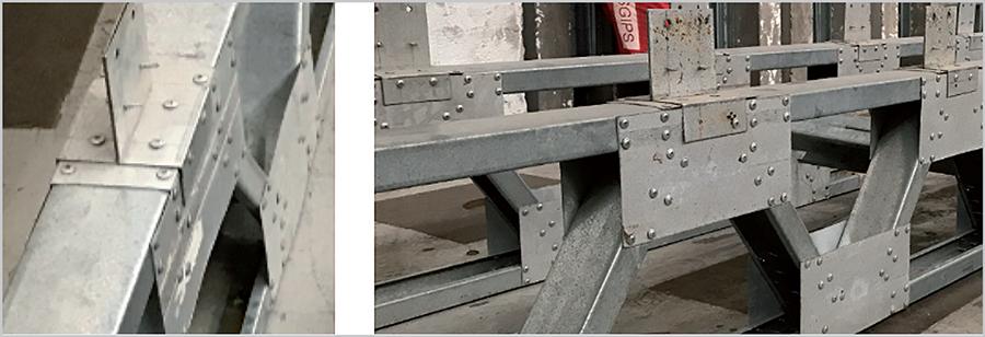
Figure 2 presents the TWP shear connector and the diagonal-chord connection reinforced by gusset plates. The TWP shear connectors are attached to the top chord by self-drilling screws: four directly connected to the web and four fixed to both flanges of the lipped channel section of the chord. In addition, it is possible to observe the reinforcement placed between the TWP and the chord of the truss, composed of a 1.25 mm thick steel plate, in order to avoid loss of effectiveness of the composite beam (Figure 2).
The TWP rib shear connector and the gusset plate reinforced connections between diagonals and chords (before pouring concrete stage of the slab).
Figure 3 shows 1.25 mm thick gusset plate reinforcement at the ends of the trussed beam, designed with sixteen screws (eight at each side of the diagonal member) in order to avoid premature collapse due to higher shear forces close to the supports. In the same figure, it is possible to see the boundary conditions (simply supported) at the end of the prototype.
In Figure 4, a lateral view of the composite steel and concrete beam can be observed. The structural member is composed of a twin "Warren" type truss configuration, 600 mm transversally spaced, similar to the typical floor design of a steel framed building. In addition, two vertical posts were included at both ends of the structure to ensure adequate load transmission to the supports.
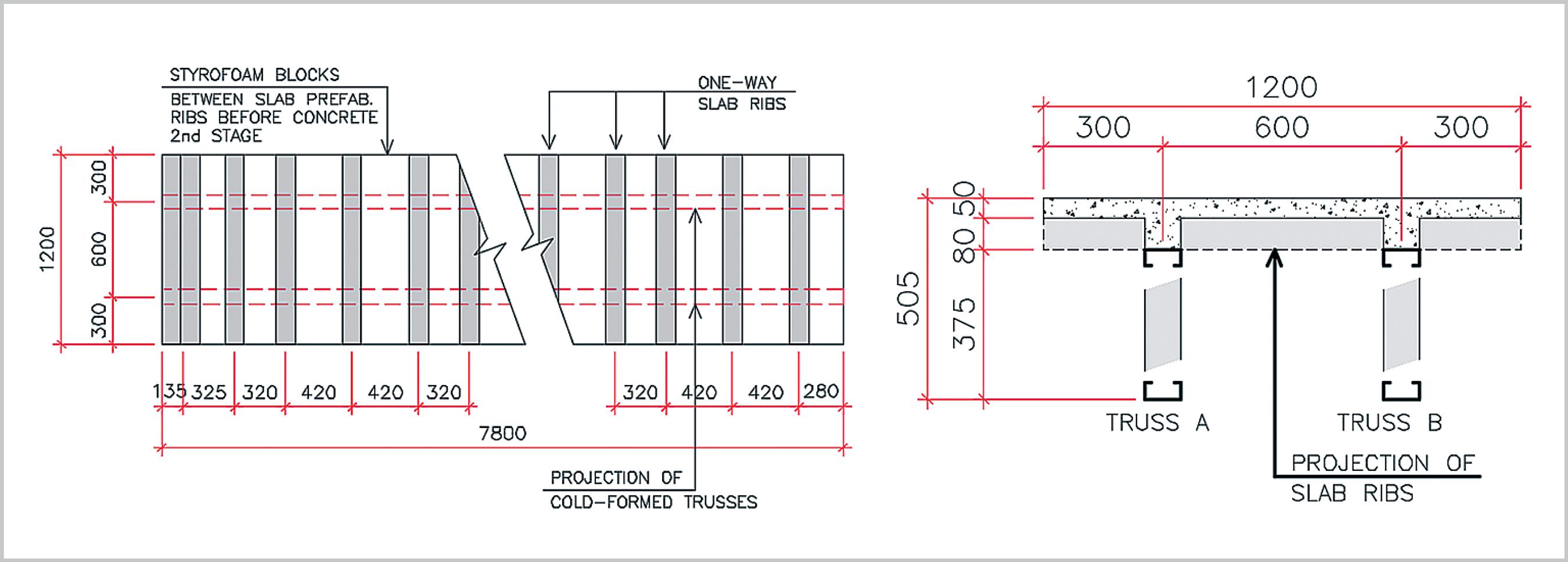
Figure 5 illustrates the top view, as well as a typical cross-section of the prototype, composed of (i) pre-cast concrete ribs and (ii) Styrofoam blocks. This solution was adopted in order to reduce formwork activities in the construction site and because it is a low-cost alternative and easily available in the civil construction market.
Another fundamental aspect regarding the concrete slab refers to the presence of a welded mesh rebar (4.2 mm diameter, 150x150 mm mesh), placed 25 mm below the top surface of the slab, which provides better stress distribution over the floor system. Furthermore, the welded mesh provides a transverse reinforcement, essential to guarantee adequate shear transfer between the steel CFS truss and the concrete slab, avoiding the collapse mode associated with premature longitudinal shear failure, as recommended by Eurocode 4 (2004).
2.2 Formwork, assembling and concrete stage
The preparation of the structural members for the second stage of concrete pouring (Figure 6) included the execution of lateral bracing of the CFS trusses, formwork assembling in the perimeter of the prototype, positioning the welded mesh rebar and steel transversal reinforcements crossing the TWP shear connectors.
During the concrete pouring, two important aspects were observed. In the first place, the bond interaction between CFS top chord of the truss and concrete slab was not avoided, producing a different shear transfer mechanism compared to the push-out tests. Although this contribution was not studied in this research, it probably generates benefits, such as higher shear transfer capacity and reduction of the forces in the TWP connectors.
The concrete was designed for 20MPa compressive strength. Standard cylindrical specimens (100 x 200mm) were prepared and tested, indicating an average compressive strength of 16.5MPa.
2.3 Instrumentation and test setup
The full-scale specimen was subjected to a four-point bending test, with available instrumentation providing reliable information on: (a) the effective contribution of CFS top chord in terms of flexural strength and stiffness of the prototype, (b) the stress distribution at the mid-section and (c) the experimental flexural stiffness of the composite beam.
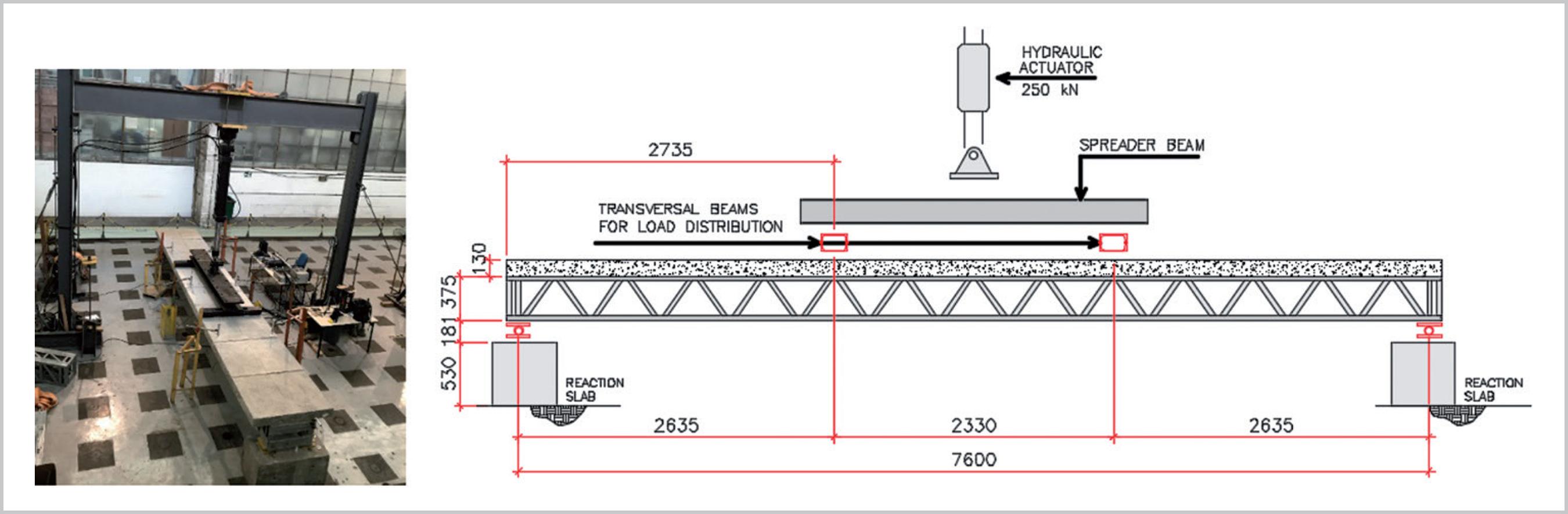
The arrangement of the four-point test is shown in Figure 7, including details related to the clear span of the composite floor (7600mm) and the extension of the pure bending zone (2330mm). To guarantee an adequate loading condition, two transverse and one longitudinal spreader steel rigid beams were positioned over the concrete slab. The total weight of the referred to members is 9.0 kN, measured before the experimental investigation.
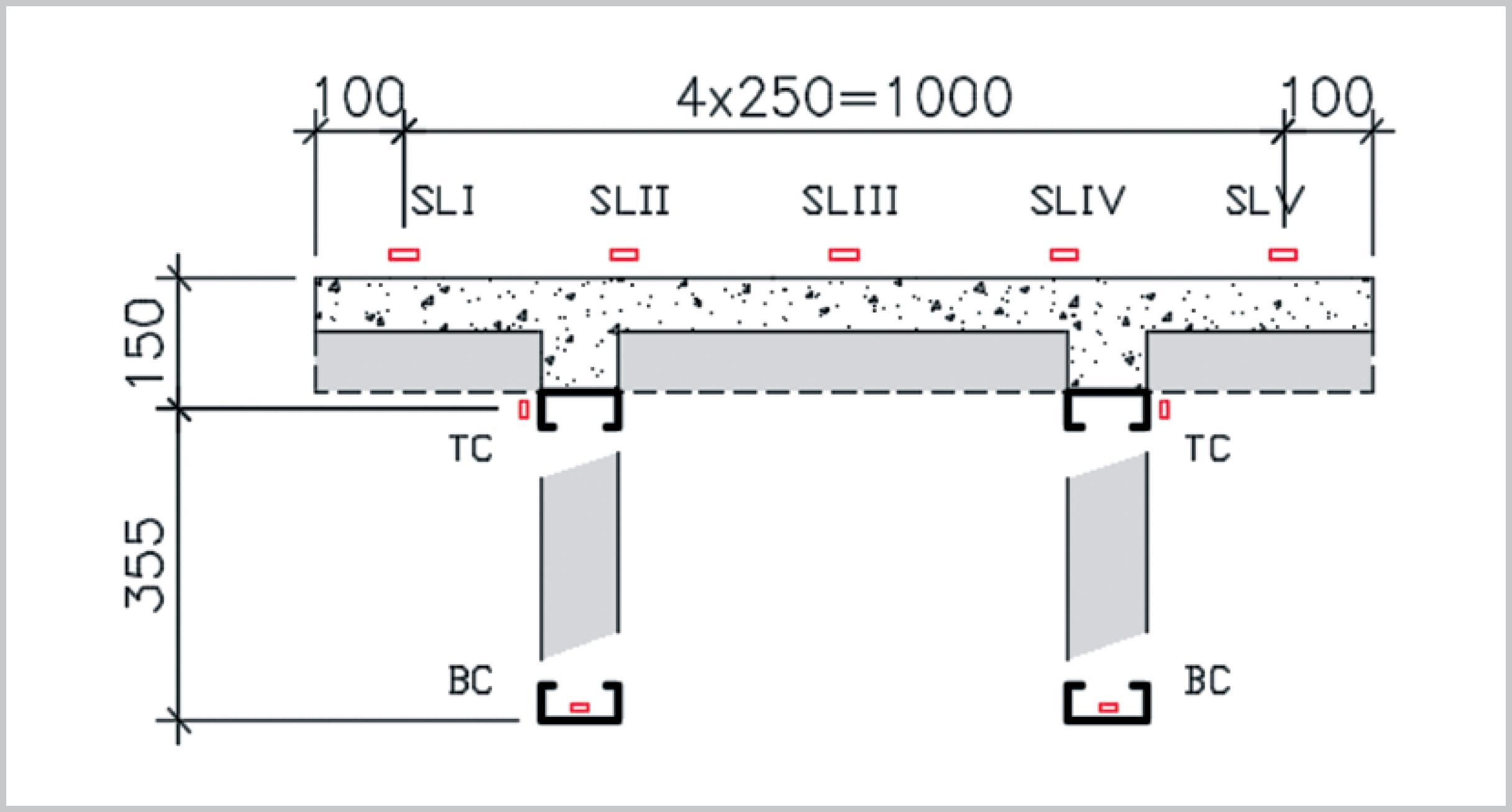
Figures 8 and 9 show the arrangement of the instrumentation positioned at the top and bottom chords of the steel trusses. Twenty strain gauges were positioned on the steel members: eight on the web of the bottom chord, eight on the flange of the top chord and four on the flange of diagonals. These strain gages are fundamental to provide information regarding the collapse mode of the composite floor system, since there are few results related to the contribution of the top chord. The sensors, located at the top and bottom chord, were denominated "Top Chord (TC)" and "Bottom Chord (BC)", respectively.
2.4 Analytical models and prediction of the ultimate load
Four analytical models for the prediction of the ultimate load are considered: (i) two of them based on linear elastic stress distribution (models 1 and 2), and (ii) the other two based on plastic stress distribution (models 3 and 4), as can be seen in Figure 10 and Table 2. It is important to mention that for all the models, the resistance of the composite cross-section is governed by the compressive stress at the upper layer of the concrete (above Styrofoam blocks), combined with tension stress at the steel truss. In addition, the effective width of the concrete slab was computed with the help of traditional code recommendations (Eurocode 4, 2004; ABNT NBR 8800, 2008; ANSI/AISC 360, 2016), which resulted in 1200mm width (full slab width).
Predicted bending moment resistance and estimated transversal forces of the experimental set up (see Fig. 10) for each analytical model.
An additional important aspect refers to the contribution of the CFS top chord. According to the recommendations established by international codes (ABNT NBR 8800, 2008; ANSI/SJI 200, 2015), the bending capacity of composite steel-concrete trusses is a function of the internal forces acting on the concrete slab and the bottom chord, neglecting the influence of the top chord. In this context, analytical models 1 and 3 do not consider the contribution of the top chord. On the other hand, models 2 and 4 take into account the referred to member for the prediction of the ultimate load of the composite floor system.
In Table 2, the predicted strength bending moment and the estimated transversal forces are indicated for each analytical model. In addition, information related to the bending moment produced by the self-weight of the prototype, as well as the additional bending moment to be generated by the hydraulic actuators are shown.
In Table 3, the material and geometrical properties are presented, associated with the composite CFS truss and adopted for estimation of the loading capacity. It is important to mention that this information is based on standard experimental tests, performed to evaluate steel and concrete mechanical properties.
Mechanical properties of the materials (average values from standard tests) and geometrical properties of the cross-section of the composite beam (effective width of the slab is 1200 mm).
For the determination of the moment of inertia, the contribution of both chords, as well as the concrete (in compression) above the neutral axis were taken into account, according to Model 2. As mentioned before, the effective width of the slab was assumed to be equal to 1200 mm, in accordance with traditional rules established by international codes (Eurocode 4, 2004; ABNT NBR 8800, 2008; ANSI/AISC 360, 2016) for composite beams.
Another important aspect refers to the internal forces acting on the composite trussed beam before the beginning of the full-scale test, produced by self-weight of the prototype and the weight of the transference steel beams. In this context, Table 4 shows an estimation of the axial deformation acting on the steel members, based on the results obtained from the load/unload stage of the experimental test.
Estimation of previous deformation (concrete and distribution steel beams self-weight) at the bottom chord and definition of the load step in which strain gages BC-03 and BC-06 reaches the yield deformation.
It is possible to observe the approximated additional axial deformation, produced by the actuator, for which the steel members reach the yield stress. Based on the information provided by Table 4, the bottom chord of the truss, next to the midsection, required an elongation of 1265 µe, produced by the hydraulic actuator at a load step of 23.1 kN. During the experimental investigation, the top chord of the composite trussed beam did not achieve the yield stress. These results are confirmed by experimental results described in the following.
2.5 Applied force vs. deformation at mid-section
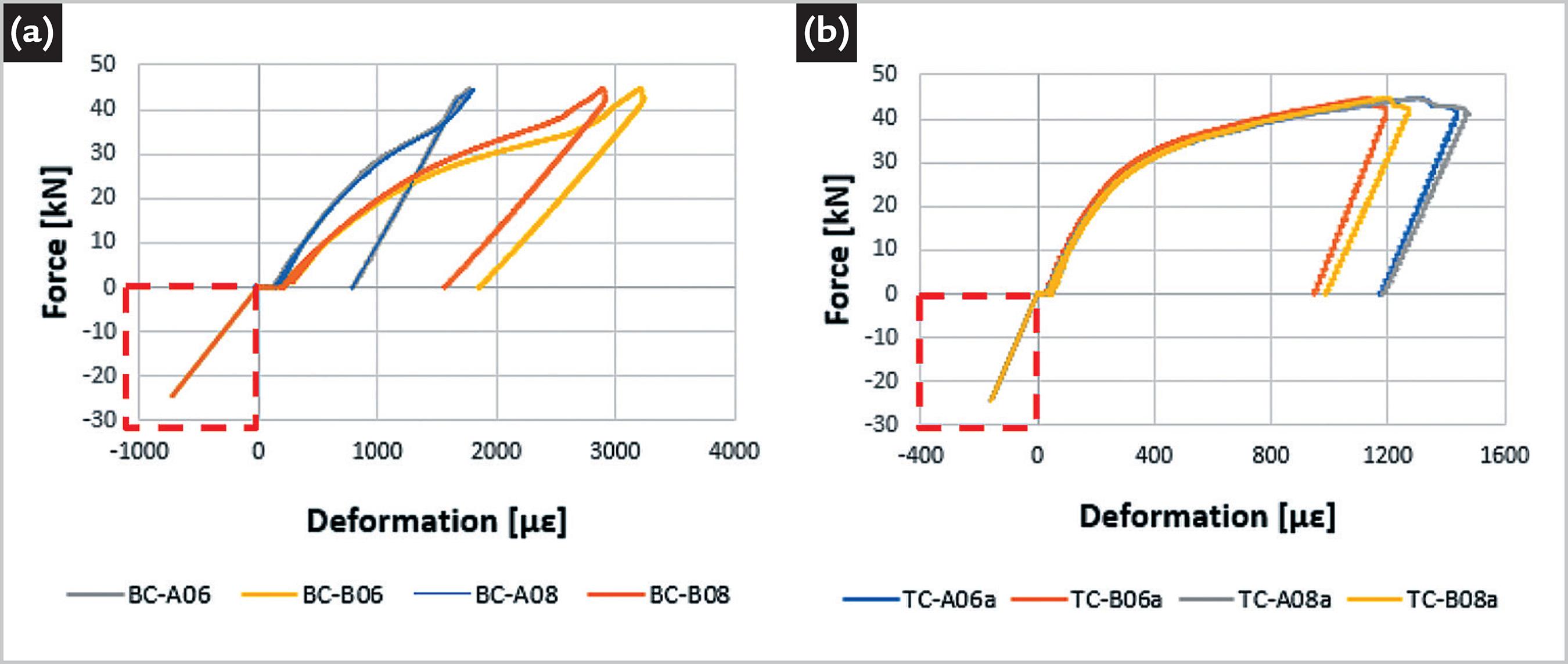
Experimental results of applied force vs. deformation (strain gages) of the chords of the steel trusses, at mid-section of the beam, are shown in Figure 11. The negative values (indicated by red rectangle) of force, as well as deformation, refers to the effects produced by the self-weight of the structure and the set-up spreader beam (see Figure 7).
Based on the experimental results, the ultimate actuator applied force is 44.7 kN, associated with the net rupture of the bottom chord of the truss. Considering the forces acting on the prototype before the beginning of the bending test, the ultimate load is 69.2 kN (24.5 kN associated with an equivalent force related to the self-weight and 44.7 kN produced by the actuator).
Observing the bottom and the top chord response, as indicated in Figure 11, notice that the prototype displayed linear behavior below the loading step of 10 kN. The non-linear behavior above the load step of 10 kN became more significant at the load step of 23.1 kN up to the collapse of the composite floor system. At this stage (23.1 kN or 33% of the ultimate load), the bottom chord of the truss reached the yield stress (additional deformation of 1265 µe, according to the estimation presented in Table 4) and, therefore, the structure was continuously affected by material nonlinearity and loss of stiffness. It is important to emphasize that the constitutive behavior of compressive concrete, as well as cracking of the slab below the neutral axis (tension zone), also contributes for the reduction of the prototype's stiffness.
Another aspect that can be observed in Figure 11, refers to the behavior of the prototype after the collapse of the structure (during the unloading stage). Note that the composite truss exhibits a linear behavior and its slope is approximately equal to the initial flexural stiffness, exhibiting recovery of the elastic deformation.
In terms of contribution of the top chord, which is usually neglected by traditional analytical procedures (ABNT NBR 8800, 2008; ANSI/SJI 200, 2015) , the estimated deformation of the referred to member, including the effect of its self-weight, was 1392 µe (axial normal stress of 262.5 MPa, approximately). In this context, based on the experimental results, the top chord of the composite trusses is able to provide increased bending capacity, as well as flexural stiffness.
2.6 Measured cross-section strain distribution
In this present study, important conclusions regarding ultimate capacity of the composite steel truss, as well as force equilibrium information, can be assessed by the evaluation of the strain distribution along the cross sections. In this context, it is possible to calculate the depth of the neutral axis, the actual contribution of top and bottom chord, as well as to establish a comparative analysis between experimental results and traditional design procedures.
Figures 12 and 13 show the measured deformations at the mid cross section, and two main aspects deserve special attention: (a) the depth of the neutral axis and (b) the eccentricity of loads and/or imperfections.
Deformation of the cross section of Truss A: strain gages in the steel BC-A06 and TC-A06a, in the concrete (average value) SL-07 (see Figures 8 and 9).
Deformation of the cross section of Truss B: strain gages in the steel BC-B06 and C-B06a, in the concrete (average value) SL-07 (see Figures 8 and 9).
Observing the strain diagrams presented in Figures 12 and 13, note that the depth of the neutral axis crossed the concrete slab and remained almost in the same position, regardless of the loading step. The referred to neutral axis position is located at 61 mm and 64 mm below the top face of the concrete slab, respectively for trusses A and B. In all cases, the adopted strain at the top of the concrete is equal to the mean value of the five adopted sensors shown in Figure 9, hereafter named "SL-07".
In terms of the eccentricity of the load, it was observed that during the bending test, the spreader beams produced an unbalanced distribution of forces on the prototype (in both transversal and longitudinal directions). At the collapse loading step, for example, the measured strains associated to trusses "A" and "B" are considerably different, indicating the presence of unevenly balanced loading in the transverse direction. One may note in Figures 12 and 13 that the deformation associated to the bottom chord of the trusses "A" and "B" are 1807 µe and 3203 µe, respectively.
2.7 Comparison between experimental results and analytical prediction
The obtained results from the four-point bending test indicate important aspects regarding (a) the ultimate capacity of the composite floor system and (b) the depth of the neutral axis. In this context, the experimental ultimate load of 69.2 kN (self-weight equivalent to a load of 24.5 kN plus 44.7 kN from the applied load) was almost 12%, 4% and 6% higher than the expected failure loads of 61.6, 66.5 and 65.3 kN, predicted by Models 1, 2 and 3, respectively. In addition, the predicted failure load, based on the full plastic stress distribution of the cross-section and computed with Model 4, is 82.1 kN, which is around 19% higher than the experimental results. All these expected loads were obtained by the sum of the equivalent force of 24.5 kN, produced by self-weight loads, and the estimated transversal forces P (see the last column in Table 2).
Although the results suggested a huge difference between the experimental bending capacity of the prototype and the computed value from Model 4, the authors believe the obtained data was substantially affected by the eccentricity of the actuator force.
Based on results presented by other researches (Mujagic et al, 2010MUJAGIC, J.R.U; EASTERLING, W.S; MURRAY, T.M. Design and behavior of light composite steel-concrete trusses with drilled standoff screw shear connections. Journal of Constructional Steel Research, vol. 66., p. 1483-1491, 2010.), the collapse mechanisms of the composite trusses are well related to the full plastic bending moment, taking into account the contribution of the top chord of the truss. In addition, recent full-scale tests conducted in the Structures Laboratory of COPPE confirmed this fact and will be reported in the near future.
In terms of the depth of the neutral axis, the bending test showed good agreement between experimental data and prediction associated to Model 2. Note from Table 2 that the value of 63.8 mm, based on Model 2, is close to the experimentally measured neutral axis depths, 61 and 64 mm associated with the Trusses A and B, respectively (Figures 12 and 13).
3. Conclusions
In this study, a composite floor system, composed of steel trusses, a one-way concrete slab and innovative shear connectors, were investigated in terms of flexural strength and distribution of cross-section strains. Based on experimental full-scale tests, important features related to the behavior of the composite CFS truss can be stated, such as: (a) considerable contribution of the top chord, (b) verification of analytical procedures for the computation of the ultimate load prediction, and (c) performance of the floor system including TWP connectors and self-drilling screws.
In terms of contribution of the top chord, the obtained results showed that a positive effect for the ultimate capacity of the prototype was observed. The recorded experimental results confirm the actual contribution of the referred to CFS chord members all along the loading process, including the failure configuration.
Note that the strain associated to Truss B, in an intermediate cross-section (considering the effect of its self-weight), is equal to 1468 µe, and therefore, the related stress is approximately equal to 262.5 MPa, which represents 70% of the yield stress of the steel.
Another important aspect that can be highlighted, refers to the good relationship between the experimental data and the expected analytical results. As presented, four analytical models for the prediction of the load capacity can be adopted, with two of them based on elastic distribution of strains, namely Models 1 and 2. Models 3 and 4 on the other hand take into account the plasticity effect of the materials for the computation of the internal forces for bending equilibrium.
Observing the comparison between the results included in Table 2 and the experimental data, note that the collapse of the composite CFS truss occurred at a load level of 69.2 kN, which is 12%, 6% and 4% higher than the estimated ultimate force predicted by models 1, 2 and 3, respectively.
Model 4, which considers the full plasticity of the cross-section, overestimated the strength capacity by 19%. It is important to emphasize that the authors believe that the eccentricity of the distribution of the hydraulic actuator forces was responsible for the relatively premature collapse of the composite floor system. Based on full-scale tests conducted by other researches (Mujagic et al, 2010MUJAGIC, J.R.U; EASTERLING, W.S; MURRAY, T.M. Design and behavior of light composite steel-concrete trusses with drilled standoff screw shear connections. Journal of Constructional Steel Research, vol. 66., p. 1483-1491, 2010.), the strength of the composite trussed beams is related to the full-plasticity stress distribution at the concrete slab, combined with elasto-plastic stress distribution in the chords of the steel trussed beam.
Another important aspect refers to the behavior of the TWP connected to the top chord by self-drilling screws and originally presented by Leal & Batista (2017)LEAL, L.A.A.S.; BATISTA, E.M. Experimental investigation of new thin-walled perfobond shear connectors. In: IBERIAN LATIN-AMERICAN CONGRESS ON COMPUTATIONAL METHODS IN ENGINEERING (CILAMCE), 38., 2017, Florianópolis, Brazil. Proceedings [...]. Florianópolis: ABMEC, 2017.. The shear connectors were able to provide full interaction between the steel trusses and the concrete slab, since negligible relative displacements (in longitudinal direction) between materials were recorded by displacement transducers. Additionally, at the collapse step, the top face of the concrete slab around the TWP connectors did not present any cracks or evidence that could suggest failure of the connector.
Acknowledgements
This study was financed in part by the Coordenação de Aperfeiçoamento de Pessoal de Nível Superior- Brasil (CAPES) - Finance Code 001. Moreover, the authors would like to acknowledge GypSteel Group for the delivery of the steel CFS members.
References
- AMERICAN NATIONAL STANDARD. ANSI/AISC 360-16: specification for structural steel buildings, Chicago: AISC, 2016.
- AMERICAN NATIONAL STANDARD. ANSI SJI 200: standard specification for CJ-Series composite steel joists. ANSI, Steel Joist Institute, 2015.
- ASSOCIAÇÃO BRASILEIRA DE NORMAS TÉCNICAS. ABNT NBR 8800: Design of steel and composite structures for buildings. Rio de Janeiro: ABNT, 2008.
- AZMI, M. H. Composite Open-Web Trusses with Metal Cellular Floor 1972. M.S. Thesis (Master of Engineering) - McMaster University, Hamilton, Ontario, Canada. 1972.
- EUROPEAN STANDARD. EN 1994-1-1: Eurocode 4: design of composite steel and concrete structures, part 1-1: general rules and rules for buildings. Brussels: CEN, 2004.
- LEAL, L.A.A.S.; BATISTA, E.M. Experimental investigation of new thin-walled perfobond shear connectors. In: IBERIAN LATIN-AMERICAN CONGRESS ON COMPUTATIONAL METHODS IN ENGINEERING (CILAMCE), 38., 2017, Florianópolis, Brazil. Proceedings [...] Florianópolis: ABMEC, 2017.
- MUHAMMAD, A. Behaviour of open-web steel joist in composite deck floor system 2010. M.S. Thesis (Master of Applied Science) - University of Windsor, Ontario, Canada, 2015.
- MUJAGIC, J.R.U; EASTERLING, W.S; MURRAY, T.M. Design and behavior of light composite steel-concrete trusses with drilled standoff screw shear connections. Journal of Constructional Steel Research, vol. 66., p. 1483-1491, 2010.
- TIDE, R.H.R; GALAMBOS, T.V. Composite open-web steel joists. AISC Engineering Journal Vol.7, p. 27-36, 1970.
- YANEZ, S.J; DINEHART, D.W.; SANTHANAM, S. Composite steel joist analysis using experimental stiffness factor from push-out tests. Journal of Constructional Steel Research, 137, p. 1-7, 2017.
- WANG, P.C; KALEY, D.J. Composite action of concrete slab and open-web joist (without the use of shear connectors). AISC Engineering Journal, v.4, p. 10-16, 1967.
Publication Dates
-
Publication in this collection
20 Dec 2019 -
Date of issue
Jan-Mar 2020
History
-
Received
14 Apr 2019 -
Accepted
12 Aug 2019