
Abstract
The chord length is an essential geometric property that must be defined in the analysis of isolated joints composed of hollow steel sections, as well as the boundary conditions of the test. The analysis of these parameters’ effect on the behavior of joints has been addressed by other studies, mostly with joints between circular hollow sections with compact or semi-compact cross-sections. Recent research about tubular joints has addressed cases with slender sections, where the design of joints containing these sections is still in development. In this context, this study aimed to evaluate the effect of the chord length in the behavior of T-joints between circular hollow section braces and slender rectangular hollow section chords through experimental tests and a numerical study considering the application of axial compression at the braces. The joint behavior was examined through the load-strain and load-deformation curves and the von Mises stress distribution, which allowed the failure mode's determination and the joint resistance value. Chord face failure was observed in the prototypes. It was concluded that a minimum chord length of 0.6m would be the adequate value for the study of the T-joints containing the geometric properties used in this study, which would be equivalent to a chord length five times higher than the width of the cross-section (5b0).
Keywords:
tubular joints; steel structures; slender sections; chord length
Introduction
The design of joints between tubular sections is currently contemplated in several design guides and normative prescriptions, such as ISO 14346 (ISO, 2013INTERNATIONAL ORGANIZATION FOR STANDARDIZATION. ISO 14346: Static design procedure for welded hollow-section joints - Recommendations. Geneva: ISO, 2013.), EN 1993-1-8 (CEN, 2005)EUROPEAN COMMITEE FOR STANDARDIZATION. EN 1993-1-8: Eurocode 3: design of steel structures. Part 1-8: design of joints. Brussels: CEN, 2005., NBR 16239 (ABNT, 2013ASSOCIAÇÃO BRASILEIRA DE NORMAS TÉCNICAS. ABNT NBR 16239: Projeto de estruturas de aço e de estruturas mistas de aço e concreto de edificações com perfis tubulares. Rio de Janeiro: ABNT, 2013.), and CIDECT Design Guide (Packer et al., 2009PACKER, J. A.; WARDENIER, J.; ZHAO, X. L.; VEGTE, G. J. VAN DER; KUROBANE, Y. Design guide for rectangular hollow section (RHS) joints under predominantly static loading. 2nd. ed. Koln, Germany: LSS Verlag, 2009.). The design equations do not contemplate joints containing chords with slender cross-sections and were mainly originated from studies of isolated joints, in which the proper boundary conditions must be considered to accurately analyze the joint behavior (Vegte; Makino, 2010VEGTE, G. J. van der.; WARDENIER, J.; PUTHLI, R. S. FE analysis for welded hollow-section joints and bolted joints. Proceedings of the Institution of Civil Engineers - Structures and Buildings, v. 163, n. 6, p. 427–437, 2010.). The boundary conditions must be properly chosen in the analysis, which can exclude the influence of bending moments in the joint region.
Therefore, in the analysis of isolated joints, a minimum chord length must be considered to avoid its influence on the joint ultimate bearing capacity, as well as the proper boundary conditions. Vegte (1995)VEGTE, G. J. van der. The static strength of uniplanar and multiplanar tubular T- and X-joints. 1995. Thesis (Doctoral) - Faculty of Civil Engineering and Geosciences, Delft University of Technology, Netherlands, 1995., in the analysis of X-joints with circular hollow sections (CHS), concluded that, for chord sections with slenderness values equal to 25.4, a minimum chord length of 6 times its diameter (d0) should be used.
In CHS T-joints under axial brace loading, Vegte and Makino (2006)VEGTE, G. J. van der.; MAKINO, Y. Ultimate strength formulation for axially loaded CHS uniplanar T-joints. International Journal of Offshore and Polar Engineering, v. 16, n. 4, p. 305–312, 2006. developed finite element (FE) models varying the chord length (from 48cm to 114cm), the slenderness of the chord section (from 25.4 to 63.5), and the brace-to-chord ratio (from 0.25 to 0.98); the same parameters were varied in CHS X-joints in the study of Vegte and Makino (2010)VEGTE, G. J. van der.; MAKINO, Y. Further research on chord length and boundary conditions of chs T- and X-joints. Advanced Steel Construction, v. 6, n. 3, p. 879–890, 2010..
From these two studies, it was concluded that the slenderness was the parameter that most affected the ultimate bearing capacity of joints due to the more severe ovalization along chords with more slender sections. For X-joints and T-joints with compensating ending moments, it was recommended the use of chord lengths of at least 10d0, and 6d0 for X-joints with sections with slenderness values lower than 25. These conclusions were similar to the ones found by Voth and Packer (2012aVOTH, A. P.; PACKER, J. A. Numerical study and design of T-type branch plate-to-circular hollow section connections. Engineering Structures, v. 41, p. 477–489, 2012a., 2012bVOTH, A. P.; PACKER, J. A. Numerical study and design of skewed X-type branch plate-to-circular hollow section connections. Journal of Constructional Steel Research, v. 68, n. 1, p. 1–10, 2012b., 2012cVOTH, A. P.; PACKER, J. A. Branch plate-to-circular hollow structural section connections. I: Experimental investigation and finite-element modeling. Journal of Structural Engineering, v. 138, n. 8, p. 995–1006, Aug. 2012c.) when studying plate-to-CHS connections, whereas several researchers adopted the 6d0 minimum chord length criteria (Chen; Wang, 2015aCHEN, Y.; WANG, J. Axial compression physical testing of traditional and bird beak SHS T-joints. Journal of Central South University, v. 22, n. 6, p. 2328–2338, 12 Jun. 2015a., 2015bCHEN, Y.; WANG, J. Numerical study and design equations of square and diamond bird-beak SHS T-joints under axial compression. Thin-Walled Structures, v. 97, p. 215–224, 1 Dec. 2015b.; Garifullin et al., 2018GARIFULLIN, M.; PAJUNEN, S.; MELA, K.; HEINISUO, M. Finite element model for rectangular hollow section T joints. Rakenteiden Mekaniikka, v. 51, n. 3, p. 15–40, 24 Dec. 2018.).
Another factor analyzed by Vegte and Makino (2010)VEGTE, G. J. van der.; MAKINO, Y. Further research on chord length and boundary conditions of chs T- and X-joints. Advanced Steel Construction, v. 6, n. 3, p. 879–890, 2010. was the influence of boundary conditions in X-joints, either with or without chord endplates. It was observed that in joints with chord lengths lower than 10d0 and with rigid ends (with endplates), the ultimate bearing capacity was higher than in joints with free ends, a fact also observed by Fan and Packer (2017FAN, Y.; PACKER, J. A. RHS-to-RHS axially loaded X-connections near an open chord end. Canadian Journal of Civil Engineering, v. 44, n. 11, p. 881–892, Nov. 2017., 2018FAN, Y.; PACKER, J. A. RHS X-connections near an open chord end. In: HEIDARPOUR, A.; ZHAO, X-L. (ed.). Tubular structures XVI: Proceedings of the 16th International Symposium for Tubular Structures. London: Taylor & Francis Group, 2018. cap.21.) in connections near an open chord end.
In this context, the study of the chord length influence in T-joints containing chords with slender (the ratio of brace’s width divided by its thickness higher than 40) rectangular hollow sections (RHS) has not been approached by other studies and is essential to the development of research involving joints with high slender chord sections. Thus, this research studied the chord length effect on CHS-RHS T-joints with slender chords through experimental and numerical analyses.
2Experimental program
2.1Prototype properties
The experimental tests consisted of two prototypes with the same geometric – Figure 1 – and material properties, except for the different chord lengths (L0) of 0.65m and 1.00m, as shown in Table 1; since the main goal was to evaluate the effect of the chord length, these two sizes were chosen to be compared in the experimental analysis, and posteriorly were used to validate the numerical model. The thickness of the brace (t1) was constant in both prototypes. Non-dimensional parameters involving the brace’s diameter (d1), the chord thickness (t0), width (b0), and height (h0) were determined to evaluate the influence of the brace-to-chord ratio (parameter β), the chord length (parameter α) and slenderness (parameter 2γ).

The length of the braces was 0.5m. Chord ends were capped with 30cmx25cmx2cm plates. The gas-metal arc-welding process (MIG) was used in fillet-welding the CHS braces with the RHS chords; the electrode MIG ER70S-6 was used, with a specified minimum yield strength of 485MPa. The minimum indented leg sizes (tw) of the welds were 1.5 times the lower value between the chord or brace thicknesses, in accordance with the recommendations from AWS D.1.1/1.1M (2010)AMERICAN WELDING SOCIETY. AWS D1.1/D1.1M: Structural welding code - steel. Miami: AWS, 2010.; the measured values of leg sizes are shown in Table 1. The difference between the leg sizes occurred due to manufacturing conditions that are inherent to the welding process and was taken under consideration in the numerical analysis.
The prototypes contained braces centered along the chord length and were fabricated from cold-formed steel, using ASTM A500 – Grade B (ASTM, 2018AMERICAN SOCIETY FOR TESTING AND MATERIALS. ASTM A500: Standard specification for cold-formed welded and seamless carbon steel structural tubing in rounds and shapes. West Conshohoken, PA, USA: ASTM International, 2018.) RHS chords and CHS braces. For each RHS tube, the respective yield strength (fy0), ultimate strength (fu0), Young’s modulus (E), tangent modulus (Et), and percentage elongation (∆L) were measured through tensile coupon tests in the Structural Laboratory for Testing of Materials of IFMG-Congonhas Campus and were shown in Table 2. More details of the coupon tests can be found in the work of Guerra (2020)GUERRA, M. J. L. Estudo de ligações T compostas de seções tubulares de paredes esbeltas. 2020. 229 f. Tese (Doutorado em Engenharia Civil) – Escola de Minas, Universidade Federal de Ouro Preto, Ouro Preto, 2020..
2.2Instrumentation and methodology
The static tests were performed in a rigid beam, fixed in a reaction slab to provide support for the experiment components. The boundary conditions consisted of one fixed end and one fixed end with sliding. The prototype endplates were connected through bolts with the rigid beam or simply supported by rollers within a support plate with translation in the longitudinal axis enabled. In the center of the prototype, a sliding support was positioned to avoid the influence of bending moments in the joint region, which consisted of a rigid plate of 0.3m along the chord length. The general experimental setup was shown in Figure 2, with highlights of the boundary conditions.
A hydraulic actuator system, fixed in a reaction frame, was used to apply compressive loads to the braces with 500N increments. A load cell was positioned, with a pin in its end to guarantee axial loads, as shown in Figure 2. The loads and linear displacements recorded were monitored through an automatic acquisition system and a software to control the tests.

The details for the instrumentation setup of the experiments were shown in Figure 3. Six linear variable displacement transducers (LVDT) were used to record displacements with a data acquisition system. One LVDT was arranged to obtain the upper chord face vertical deformation (LVDT 1) and two to capture the maximum deformation of the sidewalls at a point 30mm below the chord upper face (LVDTs 2 and 3). LVDTs 4, 5, and 6 were positioned to monitor the entire prototype possible displacements and verify its alignment during the test. In the recordings of these LVDTs, no rigid body or relevant unequal measurements were observed.
Electrical resistance extensometers (ERE) were used to record the longitudinal strains at different parts of the chord, as shown in Figure 3. Since this research aimed to study the influence of the chord length in the joint behavior, EREs were positioned near the prototypes' ends. Furthermore, in P02, at a region closer to the joint.
3
Experimental results
3.1Deformation limit
The joint resistance can be determined by the deformation limit criterion, proposed by Lu et al. (1994)LU, L. H.; DE WINKEL, G. D.; YU, Y.; WARDENIER, J. Deformation limit for the strength of hollow section joints. In: GRUNDY, P.; HOLGATE, A.; WONG, B. (ed.). Tubular structures VI: Proceedings of the 16th International Symposium for Tubular Structures. Rotterdam: A. A. Balkema, 1994. p. 341–347., verified for cold-formed steel sections by Zhao (2000)ZHAO, X.-L. Deformation limit and ultimate strength of welded T-joints in cold-formed RHS sections. Journal of Constructional Steel Research, v. 53, n. 2, p. 149–165, 2000., and used in recent research regarding tubular T-joints (Gomes et al., 2019GOMES, N. V.; LIMA, L. R. O.; VELLASCO, P. C. G. S.; SILVA, A. T.; RODRIGUES, M. C.; COSTA-NEVES, L. F. Experimental and numerical investigation of SHS truss T-joints reinforced with sidewall plates. Thin-Walled Structures, v. 145, p. 106404, Dec. 2019.; Lima et al., 2018LIMA, L. R. O.; GUERRIEIRO, L. C. B.; VELLASCO, P. C. G. S.; COSTA-NEVES, L. F.; SILVA, A. T.; RODRIGUES, M. C. Experimental and numerical assessment of flange plate reinforcements on square hollow section T joints. Thin-Walled Structures, v. 131, p. 595–605, Oct. 2018.; Pereira et al., 2019PEREIRA, D. J. R.; SARMANHO, A. M. C.; NUNES, G. V.; GUERRA, M. J. L.; ALVES, V. N. Effect of fillet welds on T-joints with thin-walled chords. Proceedings of the Institution of Civil Engineers - Structures and Buildings, v. 172, n. 4, p. 301–312, 11 Apr. 2019.). It consists of determining the joint resistance according to the load equivalent to a 3% chord face deformation (N3%). Furthermore, a serviceability criterion of 1% deformation can also be applied, especially in joints with slender sections. Thus, if the ratio between the loads at 3%b0 (N3%) and at 1%b0 (N1%) is higher than 1.5, the serviceability criterion becomes dominant, and the joint resistance is equivalent to 1.5 N1% (Zhao, 2000ZHAO, X.-L. Deformation limit and ultimate strength of welded T-joints in cold-formed RHS sections. Journal of Constructional Steel Research, v. 53, n. 2, p. 149–165, 2000.). In the analysis of sidewall deformations, the 1%h0 and 3%h0 loads must be evaluated.
3.2Joint resistance
The load-deformation behaviors of the prototypes were shown in Figure 4 (a) and (b), according to the connection and sidewall deformations, respectively. The experimental joint resistances (Nexp) obtained using the deformation limit criterion, and the maximum numerical displacements of the upper face of the chord (∆max) and the chord sidewall (δmax) were shown in Table 3.
3.3
Load-strain
Figure 5 shows the load-strain behavior of the two tests for each ERE and prototype. Firstly, it was observed that none of the EREs recorded plastification of the chord (1874 μm/m), with a maximum recorded level lower than 400μm/m.

In analyzing the strains for stages of loads lower than the joint resistances (11.13kN for P01 and 10.17kN for P02), values of strains did not surpass 110 μm/m, which are values considerably lower than the elastic yielding strain (1874 μm/m). All EREs showed a change of curve inclinations post-yielding, especially for loads higher than 15kN, when the membrane effect could already be observed.
When analyzing the EREs in the same prototype, the EREs near the fixed ends (ERE1) presented higher deformation values than the ones near the sliding ends. When comparing the two prototypes, the differences between EREs’ results near the ends (ERE1 in P01 compared with ERE1 in P02 and ERE2 in P01 compared with ERE4 in P02) could be explained by geometric imperfections and a variation of conditions intrinsic to experimental techniques, since no significant differences were observed. Thus, the chord length variation did not preset a clear trend of influence in the prototype behavior during the experiments.
4FE modeling and results
4.1Numerical model
The FE model (Figure 6) was developed through a commercially available software – ANSYS 12.1 (ANSYS Inc., 2011ANSYS. ANSYS 12.1. Houston, PA: ANSYS Inc., 2011.) –, reproducing the experimental conditions to provide a proper comparison. This comparison is enabled by the possibility to simulate and predict the static behavior of the tubular joints that fail by plastification (Vegte; Wardenier; Puthli, 2010VEGTE, G. J. van der.; WARDENIER, J.; PUTHLI, R. S. FE analysis for welded hollow-section joints and bolted joints. Proceedings of the Institution of Civil Engineers - Structures and Buildings, v. 163, n. 6, p. 427–437, 2010.).

The material properties found on the coupon test were used for the chords, while the nominal data from ASTM A500 (ASTM, 2018AMERICAN SOCIETY FOR TESTING AND MATERIALS. ASTM A500: Standard specification for cold-formed welded and seamless carbon steel structural tubing in rounds and shapes. West Conshohoken, PA, USA: ASTM International, 2018.) was assumed for the braces. A bilinear diagram was adopted to consider the steel stress-strain behavior, considering the yield stress, Young's modulus, and the tangent modulus shown in Table 2. The tangent modulus was found based on the post-yield inclination considering strain-hardening, as described in a modeling material behavior in EN 1993-1-5 Section C.6 (CEN, 2006aEUROPEAN COMMITEE FOR STANDARDIZATION. EN 1993-1-5: Eurocode 3: design of steel structures. Part 1-5: plated structural elements. Brussels: CEN, 2006a.). The multilinear curve obtained from the coupon test was also tested in the software. The results, compared to the analysis using the bilinear diagram, were equal. Since the parametric study was performed using the bilinear diagram with the EN 1993-1-5(CEN, 2006aEUROPEAN COMMITEE FOR STANDARDIZATION. EN 1993-1-5: Eurocode 3: design of steel structures. Part 1-5: plated structural elements. Brussels: CEN, 2006a.) recommendations, it was adopted in all analyses.
The chord corners' inner and outer radii adopted in the modeling were 2.0 and 1.0 times the chord's thickness (t0), respectively, according to the recommendation for cold-formed hollow steel sections (CEN, 2006bEUROPEAN COMMITEE FOR STANDARDIZATION. EN 10219-2: Cold formed welded structural hollow sections of non-alloy and fine grain steels - Part 2: tolerances, dimensions and sectional properties. Brussels: CEN, 2006b.). A 3-D modeling element used to simulate solid structures – SOLID185 – was the finite element chosen, being defined by eight nodes having translations on three of the nodal directions at each node (ANSYS Inc., 2011ANSYS. ANSYS 12.1. Houston, PA: ANSYS Inc., 2011.).
Using the mechanical and geometric properties of the experimental prototypes P01 and P02, different finite element mesh configurations were tested in the numerical model. The results of load-deformation behaviors were shown in Figure 7 for the medium mesh sizes of 2, 5, and 8mm. As anticipated, higher dispersion levels were found in the coarse mesh (8mm medium-size elements) compared to the experimental results. A medium (5mm) and a fine mesh (2mm) were also tested, being the medium the one adopted, since it presented adequate correlation values (Figure 7).

Displacements were applied to the brace, and boundary conditions were imposed to replicate the experiments, with node coupling in the ends. Translations were restricted to simulate the fixed end. Translation in the longitudinal axis was enabled to simulate the sliding end, and in the transversal axis to simulate the central support. Geometric and material non-linearity were considered, and a solution convergence through the iterative method of Newton-Raphson.
4.2Results comparison
The load-connection deformation FE results were shown in Figure 8 alongside the experimental curves. The joint resistances – Table 4 – obtained from the numerical models (Nnum) were 1% and 18% higher than the P01 and P02 experimental resistances, respectively. A linear trend until the 1%b0 deformation and a post-buckling membrane effect were observed in the numerical and experimental curves. Therefore, the numerical model was considered adequate to simulate the joint behavior of the prototypes analyzed.
5
Numerical analysis of chord length and boundary conditions variations
Using the validated numerical model, the influence of the chord length size and the boundary conditions in the joint behavior were evaluated. The joints contained the properties described in the experimental study, with seven models of different lengths – Table 5 – and two different boundary conditions: the exact experimental conditions described and shown in Figure 2 (with central support) and a condition similar to the experiments, but without the central support. This condition without central support is similar to the condition shown in Figure 2, with the difference of translations free along the Y-axis near the joint region, allowing the occurrence of bending moments.
In Figure 9, it is shown that all models have different joint resistances for the case without central support.

Therefore, the chord length directly influenced the results, which could be explained by bending moments in the joint region. Thus, the condition with central support enabled the analysis of the chord length influence in the joint resistance, since bending moments were not acting in the joint region.
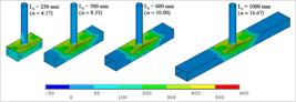
For the cases with central supports, the chord length did not influence the joint resistance for models with lengths higher or equal to 600mm, which was also observed in the von Mises stress distribution in Figure 10.
The results from the load-displacement curves of the parametric study are shown in Figure 11. It was observed that the initial linear trend inclination until the 1%b0 displacement became different between models with different boundary conditions, which influenced the joint resistance shown in Table 5. The behavior of T-joints containing chord with slender sections with chord face plastification was also discussed by Guerra et al. (2021)GUERRA, M.; PEREIRA, D.; SILVA NETO, J. B.; NUNES, G.; SARMANHO, A.; LIMA, L. Structural behaviour of thin-walled CHS-RHS T-joints: Experimental and numerical assessment. Structures, v. 32, p. 548–561, Aug. 2021. and Neto et al. (2021)SILVA NETO, J. B.; NUNES, G. V.; SARMANHO, A. M. C.; PEREIRA, D. J. R.; GUERRA, M. J. L.; ALVES, V. N. Experimental and numerical assessment of CHS-RHS T-joints with chords subjected to axial tensile forces. Advances in Structural Engineering, p. 136943322110032, 8 Apr. 2021., who observed that the serviceability limit was dominant in these cases. This was also observed in this parametric study, as shown by the N3%/N1% results in Table 5.
6.
Conclusions
In the experimental tests with two different chord lengths – 0.65m and 1.00m –, both prototypes presented chord face failure after applying axial forces of compression at the braces.
The joint resistance, obtained from the deformation limit criterion, in the prototype with a 0.65m chord length was 9.4% higher than in the prototype with a 1.00m chord length. These joint resistances were calculated based on the loads at a 1% chord face deformation. Considering the loads at a 3% face deformation, the difference between prototypes became lower, equal to 3.8%.
However, the load-deformation curve showed that the joint behavior had similar trends, when a linear trend until the 1%b0 deformation was achieved and a post-buckling membrane effect. Geometric imperfections could explain the difference between experimental results since the load-strain results did not indicate an evident influence of the chord length in the joint region.
The numerical FE model developed was able to properly simulate the joint behavior when compared to the experimental results, which enabled the parametric study. According to the parametric study, a minimum chord length of 0.6m would be adequate in the study of CHS-RHS isolated T-joints containing the geometric properties used in this study. Thus, a minimum chord length five times higher than the cross-section width (5b0) would be necessary.
Therefore, in accordance with the recommendations of Vegte and Makino (2006VEGTE, G. J. van der.; MAKINO, Y. Ultimate strength formulation for axially loaded CHS uniplanar T-joints. International Journal of Offshore and Polar Engineering, v. 16, n. 4, p. 305–312, 2006., 2010) for CHS-CHS T-joints with compact and semi-compact sections, a minimum chord length of 6b0 would be adequate in the analysis of isolated CHS-RHS T-joints with slenderness values lower than 59, brace-to-chord ratios of 0.42 and that fail by chord face plastification.
Acknowledgment
The authors are grateful for the support from Coordenação de Aperfeiçoamento de Pessoal de Nível Superior (CAPES), Universidade Federal de Ouro Preto (UFOP), Conselho Nacional de Desenvolvimento Científico e Tecnológico (CNPq) – Finance code 307455/2019-0, and IFMG.
References
- AMERICAN SOCIETY FOR TESTING AND MATERIALS. ASTM A500: Standard specification for cold-formed welded and seamless carbon steel structural tubing in rounds and shapes. West Conshohoken, PA, USA: ASTM International, 2018.
- AMERICAN WELDING SOCIETY. AWS D1.1/D1.1M: Structural welding code - steel. Miami: AWS, 2010.
- ANSYS. ANSYS 12.1 Houston, PA: ANSYS Inc., 2011.
- ASSOCIAÇÃO BRASILEIRA DE NORMAS TÉCNICAS. ABNT NBR 16239: Projeto de estruturas de aço e de estruturas mistas de aço e concreto de edificações com perfis tubulares. Rio de Janeiro: ABNT, 2013.
- CHEN, Y.; WANG, J. Axial compression physical testing of traditional and bird beak SHS T-joints. Journal of Central South University, v. 22, n. 6, p. 2328–2338, 12 Jun. 2015a.
- CHEN, Y.; WANG, J. Numerical study and design equations of square and diamond bird-beak SHS T-joints under axial compression. Thin-Walled Structures, v. 97, p. 215–224, 1 Dec. 2015b.
- EUROPEAN COMMITEE FOR STANDARDIZATION. EN 1993-1-8: Eurocode 3: design of steel structures. Part 1-8: design of joints. Brussels: CEN, 2005.
- EUROPEAN COMMITEE FOR STANDARDIZATION. EN 1993-1-5: Eurocode 3: design of steel structures. Part 1-5: plated structural elements. Brussels: CEN, 2006a.
- EUROPEAN COMMITEE FOR STANDARDIZATION. EN 10219-2: Cold formed welded structural hollow sections of non-alloy and fine grain steels - Part 2: tolerances, dimensions and sectional properties. Brussels: CEN, 2006b.
- FAN, Y.; PACKER, J. A. RHS-to-RHS axially loaded X-connections near an open chord end. Canadian Journal of Civil Engineering, v. 44, n. 11, p. 881–892, Nov. 2017.
- FAN, Y.; PACKER, J. A. RHS X-connections near an open chord end. In: HEIDARPOUR, A.; ZHAO, X-L. (ed.). Tubular structures XVI: Proceedings of the 16th International Symposium for Tubular Structures. London: Taylor & Francis Group, 2018. cap.21.
- GARIFULLIN, M.; PAJUNEN, S.; MELA, K.; HEINISUO, M. Finite element model for rectangular hollow section T joints. Rakenteiden Mekaniikka, v. 51, n. 3, p. 15–40, 24 Dec. 2018.
- GUERRA, M.; PEREIRA, D.; SILVA NETO, J. B.; NUNES, G.; SARMANHO, A.; LIMA, L. Structural behaviour of thin-walled CHS-RHS T-joints: Experimental and numerical assessment. Structures, v. 32, p. 548–561, Aug. 2021.
- GOMES, N. V.; LIMA, L. R. O.; VELLASCO, P. C. G. S.; SILVA, A. T.; RODRIGUES, M. C.; COSTA-NEVES, L. F. Experimental and numerical investigation of SHS truss T-joints reinforced with sidewall plates. Thin-Walled Structures, v. 145, p. 106404, Dec. 2019.
- GUERRA, M. J. L. Estudo de ligações T compostas de seções tubulares de paredes esbeltas 2020. 229 f. Tese (Doutorado em Engenharia Civil) – Escola de Minas, Universidade Federal de Ouro Preto, Ouro Preto, 2020.
- INTERNATIONAL ORGANIZATION FOR STANDARDIZATION. ISO 14346: Static design procedure for welded hollow-section joints - Recommendations. Geneva: ISO, 2013.
- LIMA, L. R. O.; GUERRIEIRO, L. C. B.; VELLASCO, P. C. G. S.; COSTA-NEVES, L. F.; SILVA, A. T.; RODRIGUES, M. C. Experimental and numerical assessment of flange plate reinforcements on square hollow section T joints. Thin-Walled Structures, v. 131, p. 595–605, Oct. 2018.
- LU, L. H.; DE WINKEL, G. D.; YU, Y.; WARDENIER, J. Deformation limit for the strength of hollow section joints. In: GRUNDY, P.; HOLGATE, A.; WONG, B. (ed.). Tubular structures VI: Proceedings of the 16th International Symposium for Tubular Structures. Rotterdam: A. A. Balkema, 1994. p. 341–347.
- PACKER, J. A.; WARDENIER, J.; ZHAO, X. L.; VEGTE, G. J. VAN DER; KUROBANE, Y. Design guide for rectangular hollow section (RHS) joints under predominantly static loading 2nd. ed. Koln, Germany: LSS Verlag, 2009.
- PEREIRA, D. J. R.; SARMANHO, A. M. C.; NUNES, G. V.; GUERRA, M. J. L.; ALVES, V. N. Effect of fillet welds on T-joints with thin-walled chords. Proceedings of the Institution of Civil Engineers - Structures and Buildings, v. 172, n. 4, p. 301–312, 11 Apr. 2019.
- SILVA NETO, J. B.; NUNES, G. V.; SARMANHO, A. M. C.; PEREIRA, D. J. R.; GUERRA, M. J. L.; ALVES, V. N. Experimental and numerical assessment of CHS-RHS T-joints with chords subjected to axial tensile forces. Advances in Structural Engineering, p. 136943322110032, 8 Apr. 2021.
- VEGTE, G. J. van der. The static strength of uniplanar and multiplanar tubular T- and X-joints 1995. Thesis (Doctoral) - Faculty of Civil Engineering and Geosciences, Delft University of Technology, Netherlands, 1995.
- VEGTE, G. J. van der.; MAKINO, Y. Ultimate strength formulation for axially loaded CHS uniplanar T-joints. International Journal of Offshore and Polar Engineering, v. 16, n. 4, p. 305–312, 2006.
- VEGTE, G. J. van der.; MAKINO, Y. Further research on chord length and boundary conditions of chs T- and X-joints. Advanced Steel Construction, v. 6, n. 3, p. 879–890, 2010.
- VEGTE, G. J. van der.; WARDENIER, J.; PUTHLI, R. S. FE analysis for welded hollow-section joints and bolted joints. Proceedings of the Institution of Civil Engineers - Structures and Buildings, v. 163, n. 6, p. 427–437, 2010.
- VOTH, A. P.; PACKER, J. A. Numerical study and design of T-type branch plate-to-circular hollow section connections. Engineering Structures, v. 41, p. 477–489, 2012a.
- VOTH, A. P.; PACKER, J. A. Numerical study and design of skewed X-type branch plate-to-circular hollow section connections. Journal of Constructional Steel Research, v. 68, n. 1, p. 1–10, 2012b.
- VOTH, A. P.; PACKER, J. A. Branch plate-to-circular hollow structural section connections. I: Experimental investigation and finite-element modeling. Journal of Structural Engineering, v. 138, n. 8, p. 995–1006, Aug. 2012c.
- ZHAO, X.-L. Deformation limit and ultimate strength of welded T-joints in cold-formed RHS sections. Journal of Constructional Steel Research, v. 53, n. 2, p. 149–165, 2000.
Publication Dates
-
Publication in this collection
20 Sept 2021 -
Date of issue
Oct-Dec 2021
History
-
Received
23 Dec 2020 -
Accepted
04 June 2021


