 Experimental-numerical comparative study of thermal deformations of a reinforced concrete outer wall of the anode block cooking chamber in the primary aluminum industry
Abstract
Abstract This study focuses on the analysis of the deformations of a reinforced concrete wall exposed to high temperatures, such as those found in anode baking furnaces employed in the production of primary aluminum. The main problem addressed is the structural displacement of the concrete due to intense thermal variations, which can compromise the integrity, durability and performance of the structure over time. The objective of the research was to investigate and understand the behavior of concrete displacements under high-temperature working conditions, simulating the thermal and mechanical demands faced in the industrial process. For this purpose, an experimental approach was adopted, involving displacement transducers and temperature sensors, both connected to a data acquisition system, which allowed continuous and automatic collection of samples over time. In parallel, a numerical model was developed based on the finite element method (FEM). This model allowed the simulation of the temperature distribution within the concrete wall and the evaluation of the associated stresses and deformations, caused mainly by thermal expansion and transient creep. The combination of experimental and numerical analyses allowed a better understanding of the structural response at high temperatures. The experimental and numerical results were compared to validate the accuracy of the model, confirming its effectiveness in simulating the thermal and mechanical behavior of concrete. The analysis suggests that although reinforced concrete has considerable strength, the impact of extreme temperatures on its mechanical and thermal properties leads to significant deformations, which can affect the long-term durability and safety of the structure. These findings reinforce the importance of considering thermal protection and continuous monitoring of structures exposed to high-temperature environments.
Keywords:
thermal deformations; reinforced concrete; finite element method; high temperatures
Resumo
Resumo Este estudo concentra-se na análise das deformações de uma parede de concreto armado exposta a altas temperaturas, como as encontradas em fornos de cozimento de anodos utilizados na produção de alumínio primário. O principal problema abordado é o deslocamento estrutural do concreto devido às intensas variações térmicas, que podem comprometer a integridade, durabilidade e desempenho da estrutura ao longo do tempo. O objetivo da pesquisa foi investigar e compreender o comportamento dos deslocamentos do concreto sob condições de trabalho em altas temperaturas, simulando as exigências térmicas e mecânicas enfrentadas no processo industrial. Para isso, foi empregada uma abordagem experimental, utilizando transdutores de deslocamento e sensores de temperatura, ambos conectados a um sistema de aquisição de dados, que permitiu a coleta contínua e automática das amostras ao longo do tempo. Paralelamente, um modelo numérico foi desenvolvido com base no método dos elementos finitos (MEF). Esse modelo permitiu a simulação da distribuição de temperatura dentro da parede de concreto e a avaliação das tensões e deformações associadas, causadas principalmente pela expansão térmica e creep transitório. A combinação das análises experimentais e numéricas possibilitou uma melhor compreensão da resposta estrutural em altas temperaturas. Os resultados experimentais e numéricos foram comparados para validar a precisão do modelo, confirmando sua eficácia na simulação do comportamento térmico e mecânico do concreto. A análise sugere que, embora o concreto armado tenha resistência considerável, o impacto das temperaturas extremas sobre suas propriedades mecânicas e térmicas leva a deformações significativas, o que pode afetar a durabilidade e a segurança da estrutura a longo prazo. Esses achados reforçam a importância de se considerar a proteção térmica e o monitoramento contínuo de estruturas expostas a ambientes de alta temperatura.
Palavras-chave:
deformações térmicas; concreto armado; método dos elementos finitos; altas temperaturas
1 INTRODUCTION
The primary aluminum industry plays have an important role in supplying aluminum, which is used in a variety of applications, from construction to the manufacture of consumer goods. The primary aluminum production is achieved with the Hall-Héroult process, the most efficient version of which relies on the use of prebaked carbon anode blocks within electrolysis cells operating at about 960°C. In short, the dissolved alumina (Al2O3) in the cell reacts with the carbon of the anode blocks to form CO and CO2, and as a result, pure aluminum is obtained [1].
The prebaked anode block is manufactured by compacting a paste made of a petroleum coke and tar pitch and baking process in high temperatures furnaces. This process ensures that the blocks acquire the chemical and mechanical properties necessary to the process. To subsequently introduce support rods to be inserted into the electrolytic cell [1], [2].
The anode baking furnace operates at a maximum temperature of approximately 1300°C and is divided into multiple sections, each containing combustion chambers known as Flue Walls. The anode baking process involves four key steps: preheating, forced firing, forced cooling, and natural cooling [1] (Figure 1).

These stages operate within specific temperature ranges. The first stage, pre-heating, requires the temperature to reach 850 °C before advancing to the second stage, forced firing, where it is maintained between 1220 °C and 1300 °C to bake the anode block within a predefined period. After that, the process moves to the third stage, forced cooling, in which the temperature must be reduced to 300 °C before proceeding to the final stage, natural cooling. In this last phase, the section is allowed to cool down to room temperature, completing the cycle. These four stages together are referred to as a “fire”.
The complete fire movement into all the sections of the furnace is called cycle, which is a service life measurement.
In the fuel wall, heat is generated by burning fuel and gases released when the tar pitch burns. With a ventilation and exhaust system, the fire travels through the sections, feeding heat to the anode cooking pits. This heat is transferred by convection to the refractory block wall and then by conduction to the anode baking chamber (Figure 2).

Similarly, heat is transferred to the subject of this study, the reinforced concrete wall, which runs along the entire side of the furnace, following the same heat transfer mechanisms.
The walls that make up the flue wall are composed of commercial refractory bricks, which are subjected to chemical (high temperature corrosion), mechanical (creep, walls, anode loading and unloading) and thermal (high temperature, thermal shock) conditions during the baking process. The resulting stress causes chemical and physical alterations across the width of the wall. This stress generally manifests in the failure, cracking and bending of flue walls [3]. The mechanical behavior of the structure under study is presented in Section 2.1.
The operation of the furnace has a direct impact on the reinforced concrete wall adjacent to the flue walls, an effect that is expected and considered in the design phase. However, the occurrence of pathologies, such as deformations, cracks and excessive wear of the refractory materials of the flue wall, intensifies the negative effects on the concrete wall. These pathologies compromise the efficiency of the flue wall in insulating and distributing heat uniformly, resulting in a more direct and irregular exposure of the concrete wall to intense thermal variations.
The object of study is a concrete wall composed of layers of insulating concrete and conventional reinforced concrete, located at the end of the anode baking furnaces. This structure has been in operation for over 20 years, with maintenance performed exclusively on the refractory part, which serves the critical function of containing the heat flow generated during the baking process. Its ability to withstand thermal expansion and contraction is essential for maintaining structural integrity and ensuring the efficiency of the production system.
According to Azenha [4], Heat transfer in concrete can occur in three different ways. The first is by conduction, where thermal energy is transmitted by the movement of molecules due to their vibrations, or even by the movement of electrons. The second way is by convection, which involves the movement of fluids: hot fluids rise, being replaced by colder fluids in a continuous cycle. Finally, heat transfer by radiation occurs through the emission of electromagnetic waves, without the need for a material medium for propagation.
When subjected to high temperatures, conventional concrete experiences a significant reduction in its service life, which often results in the need for constant maintenance. Under these conditions, structural elements experience significant increases in temperature, triggering a series of physical and chemical transformations in the materials that compose the structure [5], [6]. These changes lead to a progressive degradation of thermal properties, such as heat conduction capacity, in addition to compromising mechanical properties, such as compressive strength and concrete stiffness [7], [8].
The mechanical properties of concrete are substantially compromised when exposed to elevated temperatures, the extent of this deterioration being dependent on the level and duration of thermal exposure. As the temperature increases, the physical and chemical changes in concrete become more pronounced, resulting in a marked loss of performance [9], [10], [11].
Transient creep in concrete is the strain that occurs during the initial heating of a concrete member under load, particularly when it is subjected to a constant rate of heating, significantly contributing to deformation and the reduction of its mechanical properties under high temperatures. This strain is primarily driven by moisture migration and the evaporation of water as concrete is heated. Some researchers also attribute transient creep to physicochemical changes in the hydrated cement paste and the thermal incompatibility between the paste and aggregates at elevated temperatures. When concrete reaches approximately 100°C, the free and physically adsorbed moisture begins to evaporate, though this has only a marginal influence on the transient creep of concrete [8], [10].
During heating, transient creep facilitates the redistribution of internal stresses within the concrete. While this process can alleviate localized stress concentrations, it can also induce increased deformation in certain areas. As the concrete gradually deforms under the combined effects of load and heat, its stiffness decreases, making the structure more flexible and less capable of bearing loads without significant deformation. Prolonged exposure to heat exacerbates this effect, leading to the accumulation of damage over time. This progressive damage not only reduces stiffness further but also jeopardizes the structural integrity of the concrete, potentially leading to long-term performance issues [10].
In cases of unsteady heat flow in concrete, the temperature is distributed non-linearly, resulting in an irregular distribution of thermal deformation, which in turn causes significant thermal stresses. These temperature variations generate complex stress patterns, which can compromise the structural integrity of the element, especially in situations of non-uniform heating or cooling [10].
In this context, given the exposure of the wall to high temperatures, which significantly compromises its structural performance, the present study will adopt an approach that combines experimental and numerical analyses. This methodology will allow a detailed investigation of the behavior of displacements, making it possible to identify how high temperatures affect the integrity of the structure.
Experimental analyses will provide data on the wall's response under extreme thermal conditions, while numerical simulations, carried out using the Finite Element Method (FEM), will allow modeling and quantifying the displacements and stresses that the structure is suffering.
Numerical analysis is a fundamental method that uses sophisticated tools to solve complex mathematical problems that, if approached analytically, could be extremely complicated or even impossible to solve. In the context of Heat Transfer, the Finite Element Method (FEM) stands out for offering fast solutions with low computational cost. This is due to the simplicity of the model, where each element has a single degree of freedom per node, represented by temperature. Furthermore, it is possible to obtain high-quality results even when working with coarser meshes, since the linear behavior of thermal conduction and the absence of deformations in the elements in a purely thermal analysis facilitate the convergence of results. Thus, FEM analyses are particularly effective in dealing with heat transfer by conduction, while convection and radiation phenomena are considered as boundary conditions, allowing a practical and efficient approach to thermal modeling [12].
2 MATERIALS AND EXPERIMENTAL PROGRAM
2.1 Structure description
The reinforced concrete walls of the anode baking chamber experience deformation as a result of temperature fluctuations associated with the operational process, which involves elevated temperatures aimed at improving the mechanical and chemical properties of the anode blocks.
To enhance the structural rigidity of each wall, a reinforced concrete column with a square cross-section measuring 50×50 cm is positioned in the central region of the plate, resting on a foundation block (Figure 3). This figure provides a comprehensive view of the entire structure under investigation, including its key dimensions.

2.1.1 Reinforced concrete wall deformation
The reinforced concrete wall of an anode block baking chamber is showing signs of deformation due to cumulative thermal movements during the operational process. Although the current deformation has not affected the furnace’s functionality, there are concerns about its potential impact on the structural integrity (Figures 4 and 5). Figure 5 presents a sketch representation of the region highlighted in Figure 4, which was previously detailed in Figure 3. It is important to note that the metallic structure shown in Figure 4 is an independent element and is not part of the structural system under analysis.

2.2 Experimental analysis
Using a data acquisition system, linear positioning sensors (model PY2, Gefran brand), and temperature sensors (PT100 type thermocouples, Team brand), the reinforced concrete wall was continuously monitored over a period of 50 days. Data collection occurred 24 hours a day, with a sample taken every 5 seconds. This intensive monitoring approach allowed for a detailed analysis of both the thermal variations and the structural deformations in the wall, offering critical insights into the wall's behavior under prolonged exposure to high temperatures and operational stresses.
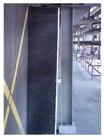
To carry out the displacement monitoring test of the reinforced concrete wall, independent metal support structures were specifically designed and constructed to mount the sensors. These support structures (Figure 6) were installed separately from the reinforced concrete structure to provide a stable reference point, ensuring they would not be influenced by mechanical deformations caused by the furnace. The thermal deformations in these metal structures were deemed negligible and therefore disregarded in the analysis.

The signal acquisition system, model ADS2000 from Lynx (Figure 7), consists of two primary modules. The first is the AC-2161A conditioner module, which handles the sensor power supply, signal reading, and conditioning (including filtering and amplification). The second is the AI-2122 controller module, responsible for converting analog signals into digital format, facilitating communication with the computer, and converting these digital signals into engineering values for analysis.

The temperature sensors were installed on both faces of the reinforced concrete wall, externally (exposed to the outside environment) and internally (at the interface with the insulating concrete), as shown in Figures 8 and 9.


2.3 Computational analysis
For this analysis, a computational model was developed using the finite element method with the assistance of Algor software. The objective was to determine the temperature distribution within the structure and to evaluate the resulting thermal stresses and deformations caused by temperature gradients. The software discretizes the geometry into finite elements and solves the governing heat transfer equations, considering conduction, convection, and radiation, under the defined material properties and boundary conditions.
Thermal modeling in Algor follows well-defined steps: it begins with the import or creation of the geometry, followed by the definition of material properties such as thermal conductivity. Next, boundary conditions are applied, including temperatures. After generating the finite element mesh, the model is processed for either steady-state or transient simulation. Finally, the results are analyzed through temperature maps, heat fluxes, and gradients, allowing for an evaluation of the structure's thermal behavior.
2.3.1 Temperatures and thermal conductivity
This study evaluates the global effect of heat generation during furnace operation. The wall temperatures were experimentally obtained through structural monitoring, enabling the assessment of the thermal response across its layers. Based on the measurements at the inner and outer faces, the temperature distribution through the insulating concrete was determined. For analytical purposes, the wall is modeled as three distinct layers: L1: reinforced concrete wall; L2: type B insulating concrete; and L3: type A insulating concrete (Figure 10).

Temperatures T1 and T2 (Figure 10) were obtained experimentally during the operation cycle. For the purpose of analysis, only the case presenting the highest thermal gradient will be considered. Additionally, the thermal conductivity of the refractory concrete was determined in a separate study, while the values for the other insulating materials were provided by their respective manufacturers.
In order to determine the temperatures T3 and T4, it was assumed that heat conduction occurs under steady-state and one-dimensional conditions. Based on these assumptions, the heat flux is considered equal across the three layers, so the temperatures at these two points can be calculated using a theoretical equation (Equation 1):
where, k=Thermal conductivity;T=temperature variation; and L=material thickness.
The temperatures were experimentally obtained using sensors placed on the internal and external surfaces, aiming to validate the theoretical results. Additionally, the temperature gradient is detailed in Section 3.3.2.
The numerical model was developed using the thermal conductivity value provided by NBR 15220-3 [13], of 1.75 W/mK.
2.3.2 Model with real dimensions
The model was developed with wall real dimensions, with the assistance of software Autodesk Algor Simulation, that is a general-purpose Multiphysics finite element analysis software and the typical uses include bending and thermal dynamics.
The Figure 11 illustrates the views of computational model of anode furnace wall. The soil (compact sand) is represented in blue; reinforced concrete is shown in pink, green, and brown; and the two types of insulating concrete are depicted in red and orange.

The boundary conditions adopted in this simulation cover both the thermal and structural problems. For heat conduction, temperatures were imposed on specific regions of the structure, and heat fluxes were applied to the surfaces to represent thermal interactions with the environment. In the case of stress analysis, displacement constraints were applied at strategic points of the model, along with distributed surface forces to simulate mechanical loads and assess the effects generated by thermal gradients.
3 RESULTS AND DISCUSSIONS
3.1 Wall cracks
The thermal effects on the wall not only lead to deformation but are also contributing to the formation of cracks. These temperature-induced stresses compromise the structural integrity of the wall, creating vulnerabilities that can affect both the stability and longevity of the structure over time.
The cracks on the inner side of the reinforced concrete wall exhibit an opening of approximately 4.00 mm. According to NBR 6118 [14], this level of crack can contribute to the corrosion of the reinforcing steel.
The reinforced concrete column exhibits greater rigidity compared to the wall, meaning that its deformation is significantly less than that of the wall. This disparity in deformation is evident in Figure 13a, which shows a crack forming around the perimeter of the column on the inner side of the wall (Figure 12). The differential movement between the column and the wall is likely a key factor contributing to this cracking. Cracks are also visible on the external side due to thermal effects (Figure 13b).


3.2 Experimental analysis
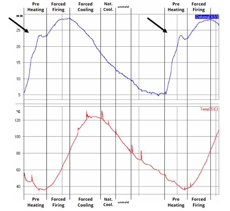
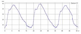
A total of 880,249 samples were collected in this experiment, and the quantitative data were analyzed in a curve chart (Figures 14 to 21), in which it is possible to observe three major cycles of result variations. These variations correspond to 18 (eighteen) days, representing the furnace operation cycle. The smaller variations correspond to the end of a daily period, caused by an external thermal variation (day/night cycle).


The anode baking furnace operating cycle is divided into interconnected stages that directly influence the thermal behavior and deformation of reinforced concrete walls. These stages, preheating, forced firing, forced cooling, and natural cooling, are characterized by temperature variations that cause expansions and contractions in the concrete.
During preheating, the temperature gradually increases, causing the concrete in the walls to begin to expand. This initial heating process leads to increased deformations, as the concrete responds to the heat with thermal expansion. In the forced firing phase, the temperature reaches its peak, and the reinforced concrete experiences intense expansion due to the high heat. This high temperature phase generates the greatest deformations, and the structure is under maximum stress. During forced cooling, the furnace temperature is reduced in a controlled manner, causing the concrete to contract as it cools. Finally, natural cooling allows the structure to slowly return to room temperature.
The presence of the spikes, which occur once daily, particularly in the temperature sensor readings, could not be definitively explained. It is possible that these anomalies were caused by electromagnetic interference during data acquisition, potentially triggered by the operation of nearby equipment or fluctuations in the factory's electrical network, which also follows a daily cycle.
The evolution of the wall deformation showed a significant discontinuity on the second day of preheating, similar to the discontinuity observed in the temperature curve in the internal process of the flue walls (Figure 22).

The delay between the peak displacement and the peak temperature is attributed to the combustion of volatile gases released during the burning of coke (Figure 23), which prolongs the thermal effect on the structure even after the initial temperature rise. This phenomenon is further influenced by the release of volatile compounds from the anode during the baking process, generating localized thermal gradients and structural stress. The observed behavior confirms the correlation between the deformation of the reinforced concrete wall and the temperature variations inherent to the operation of the anode baking furnace.

The monitored wall exhibits a distinct torsional deformation behavior, which varies depending on the phases of the furnace operational process. During the preheating and forced firing stages, the deformation occurs in a specific direction, evidencing how the temperature increases and load variations influence the structure. In contrast, in the forced cooling and natural cooling phases, the torsional deformation is reversed, reflecting the complex thermal and mechanical interaction that the concrete experiences during these transitions (Figure 24).

3.3 Computational analysis
3.3.1 Temperature and thermal conductivity estimative
When comparing the results of the experimental analysis with those of the first numerical model, significant differences were observed between the displacement values. Thus, it became necessary to determine the exact value of the thermal conductivity of concrete under the specific conditions of its application.
Azenha [4] presents a variation in thermal conductivity from 1.20 to 3.60 W/mK. In turn, Kodur et al. [7] reports a similar range, varying from 1.40 to 3.60 W/mK. In studies carried out in 2019, Kodur specifies a value of 2.00 W/mK [7]. All results were for concrete exposed to room temperature.
In preliminary studies conducted by Yamanaka et al. [16], thermal conductivity tests were performed on samples extracted from the concrete wall under investigation, which is subjected to temperatures reaching up to 1300 °C. Additionally, a comparative analysis was conducted between the measured value and standardized reference values. The thermal conductivity determined for the material was 1.18 W/m·K, and this value was subsequently adopted in the development of the numerical model.
When comparing the values found in the study with the standardized values (Table 1), a significant difference of -32.57% is observed. This significant difference can be explained by several factors. Among them, the particular operating conditions of the concrete at high temperatures for about 20 years may have influenced its thermal properties.
Table 2 summarizes the data obtained for the points shown in Figure 10. Temperatures T1 and T2 were experimentally measured during the operational cycle, while temperatures T3 and T4 were estimated using Theoretical Equation 1, based on a one-dimensional steady-state heat conduction model.
The elastic modulus was experimentally determined to validate the adopted numerical model, based on the investigations conducted by Yamanaka et al. [16] (Table 3).
The thermal conductivity values of the insulating concretes were obtained directly from technical data sheets supplied by their respective manufacturers.
3.3.2 Numerical model
The transient thermal analysis monitors the structure over time, following the loading curve to which it is subjected due to thermal effects. This analysis captures how heat propagates and accumulates within the structure under operational conditions. The experimental results indicate that the time required to reach the maximum temperature value is six days. During this period, temperature variations were recorded and plotted, demonstrating a gradual rise in heat accumulation until the peak was reached. The evolution of the temperature variation is shown in Figure 25, illustrating the progressive changes and highlighting key points in the thermal behavior of the structure.

The temperature evolution curve was recorded using auxiliary thermocouples during the anode baking process. Heat generation occurs primarily during the preheating and forced firing stages, with a total of 6 (six) days required to reach the maximum temperature.
The time factor (Figure 25) characterizes the progression of the thermal gradient, as evidenced by Meier’s study in Figure 23 [15] and corroborated by the operational behavior of the furnace.
The Figure 26 represents the temperature distribution field in the structure, the results of thermal transient analysis. This analysis consists of the effects of time, heat flux propagation, and temperature distribution within the structure, considering the specific heat capacity of the material. A two-dimensional transient heat transfer model was adopted in the simulation, considering the progressive heating of the structure over six days of operation. On the inner face of the wall, corresponding to the surface exposed to the furnace combustion environment, a temperature condition was applied according to the operational thermal cycle. On the outer face, facing the ambient environment, a convection condition was applied, assuming ambient air at 25 °C. The side surfaces of the wall were considered adiabatic (no heat flux), in order to simulate a representative section of the structure and prevent lateral heat losses. The initial condition for the entire structure was a uniform temperature equal to the ambient temperature.

The internal face of the furnace shows a progressive increase in temperature concentration from Day 1 to Day 6, with peak values exceeding 1400 °C near the heat source. A strong thermal gradient develops across the wall thickness, especially between Days 2 and 4, due to heat conduction through the insulating layers. Over time, the high-temperature zone expands toward the more external regions of the structure, reflecting the propagation of thermal energy.
The analysis was conducted by coupling a two-dimensional transient heat transfer model with a three-dimensional structural model. Specifically, the 2D transient thermal analysis (Figure 26) provided the temperature distribution across the wall section, which was subsequently mapped and applied as a thermal load in the 3D structural model (Figure 27). This coupling ensured that the structural response accurately reflected the temperature field obtained from the heat transfer simulation.

From nodal temperatures obtained in thermal analysis, it is possible to analyze tensions with this effect. The configuration of deformed structure model, due to thermic effect, is represented in Figure 27.
This analysis indicates that the greatest displacement occurs at the wall extremities, while the column shows relatively limited movement (Figure 27).
Assis et al. [17] developed, in his studies, a thermomechanical model to analyze how temperature influences the mechanical behavior of concrete under specific conditions, such as high temperatures. The results indicate that temperature causes significant changes in the modulus and in the distribution of variables along the section of the structure.
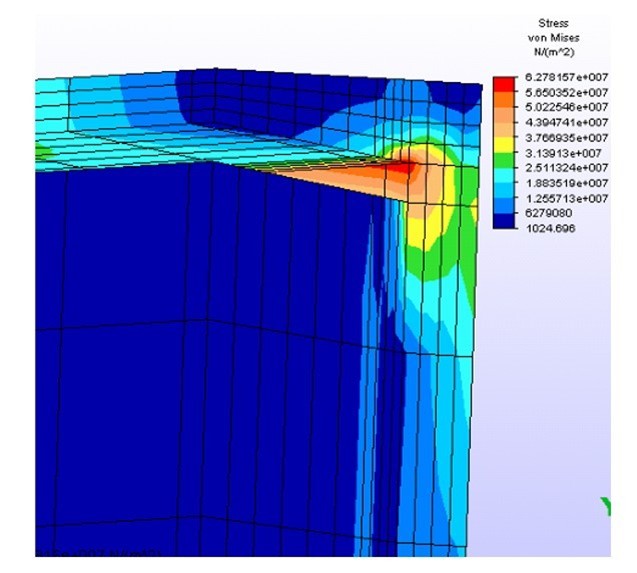
Figures 28 and 29 show the Von Mises stress distribution of the model with thermal stress. A stress concentration was observed at the end of the reinforced concrete wall, as shown in Figure 29.


It is important to emphasize that the stress results presented should be interpreted qualitatively rather than quantitatively. This analysis was performed based on the assumption that the material is linear, elastic and homogeneous, disregarding the reinforcement, which limits the accuracy in determining stresses in reinforced concrete structural elements. As a result, excessively high stress values are observed, which may not accurately reflect the actual behavior of the material under the load and temperature conditions to which it is subjected.
The experimental results were compared with the data obtained from structure monitoring to validate the numerical modeling. Table 4 summarizes the results from both the experimental measurements and the numerical model predictions, alongside the percentage variation between them.
4 CONCLUSIONS
When comparing the deformations obtained from the structural monitoring with those generated by the developed computational model, which incorporated the actual dimensions of the structure, a strong correlation was observed, particularly in the upper half of the wall. This suggests that the model effectively captured the behavior of the structure in this region under thermal and mechanical loads.
The comparison shows that the numerical model performs well for some sensors (such as Sensor 1, with a variation of 5.59%), but there are significant discrepancies for others. For instance, Sensor 3 and Sensor 6 show very high percentage variations of 96.18% and 93.45%, respectively, indicating a significant deviation between the experimental and model results. In contrast, some sensors, such as Sensor 2 and Sensor 4, show a near-perfect match between the experimental and modeled values.
Large discrepancies, especially in Sensors 8, 9, and 10 (Figure 8), may suggest localized effects or boundary conditions that the model failed to account for, such as unanticipated temperature gradients, material heterogeneities, or inaccuracies in sensor placement or calibration.
The wall deformation coincides with the different operational stages of the anode baking furnace, which include preheating, forced firing, forced cooling and natural cooling. It was observed that the complete deformation cycle unfolds in 6 days of progressive increase in deformation, followed by 18 days of reduction. This dynamic confirms the relationship between the temperature variation during furnace operation and the deformation behavior of the reinforced concrete wall, evidencing the direct impact of the thermal phases on the structural integrity of the wall.
Considering the stresses induced by wall deformation and the fact that the reinforced concrete column is continuously exposed to high temperatures, simply increasing the stiffness of the column is not enough to prevent displacement of the structure. This is because, even with increased stiffness, the reinforced concrete would continue to suffer significant degradation of its thermal and mechanical properties due to the high temperature. In addition, the deformations in the wall would cause an increase in the number and thickness of cracks around the column, intensifying the concentration of stresses in the vicinity of the column.
In conclusion, this study provided a comprehensive investigation into the structural behavior of reinforced concrete walls under high-temperature conditions, typical of the anode baking process. Through experimental monitoring and numerical modeling, the analysis revealed a direct correlation between temperature variations and structural deformations, confirming that the operational stages of the furnace significantly influence the mechanical and thermal responses of the wall. Although the numerical model succeeded in replicating some of the experimental data, discrepancies observed in some sensors underscored the complexities involved in modeling high-temperature effects on reinforced concrete. The findings highlighted that increasing structural stiffness alone is insufficient as a mitigation strategy, given the ongoing degradation of mechanical properties at elevated temperatures.
ACKNOWLEDGEMENTS
To the Federal University of Pará – UFPA.
-
Financial support:
None.
-
Data Availability:
The data that support the findings of this study are available from the corresponding author, [FMY], upon reasonable request.
-
How to cite:
F. M. Yamanaka, R. M. Souza, and M. R. Teixeira, “Experimental-numerical comparative study of thermal deformations of a reinforced concrete outer wall of the anode block cooking chamber in the primary aluminum industry,” Rev. IBRACON Estrut. Mater., vol. 18, no. 4, e18406, 2025, https://doi.org/10.1590/S1983-41952025000400006
REFERENCES
-
1 F. Grégoire and L. Gosselin, "Comparison of three combustion models for simulating anode baking furnaces," Int. J. Therm. Sci., vol. 129, pp. 532–544, 2018, http://doi.org/10.1016/j.ijthermalsci.2018.04.006
» http://doi.org/10.1016/j.ijthermalsci.2018.04.006 -
2 K. Azari, H. Alamdari, G. Aryanpour, D. Ziegler, D. Picard, and M. Fafard, "Compaction properties of carbon materials used for prebaked anodes in aluminum production plants," Powder Technol., vol. 246, pp. 650–657, 2013, http://doi.org/10.1016/j.powtec.2013.06.025
» http://doi.org/10.1016/j.powtec.2013.06.025 -
3 N. Oumarou, D. Kocaefe, and Y. Kocaefe, "Investigation of the refractory bricks used for the flue wall of the horizontal anode baking ring furnace," Ceram. Int., vol. 42, no. 16, pp. 18436–18442, 2016, http://doi.org/10.1016/j.ceramint.2016.08.178
» http://doi.org/10.1016/j.ceramint.2016.08.178 - 4 M. A. D. Azenha, “Numerical simulation of the structural behaviour of concrete since its early ages,” Ph.D. dissertation, Sch. Eng., Univ. Porto, Porto, 2009.
- 5 R. A. S. Rocha, "Efeito de alta temperatura em concretos: uma revisão da literatura," Rev. InterScientia, vol. 6, no. 1, pp. 211–227, 2018.
- 6 K. Venkatesh, "Properties of concrete at elevated temperatures," Int. Sch. Res. Notices, vol. 2014, no. 1, pp. 468510, 2014, http://dx.doi.org/10.1155/2014/468510.
-
7 V. K. R. Kodur, S. Banerji, and R. Solhmirzaei, "Test methods for characterizing concrete properties at elevated temperature," Fire Mater., vol. 44, no. 3, pp. 381–395, 2019, http://doi.org/10.1002/fam.2777
» http://doi.org/10.1002/fam.2777 -
8 S. Alogla and V. K. R. Kodur, "Quantifying transient creep effects on fire response of reinforced concrete columns," Eng. Struct., vol. 174, pp. 885–895, 2018, http://doi.org/10.1016/j.engstruct.2018.07.093
» http://doi.org/10.1016/j.engstruct.2018.07.093 -
9 V. Patel, B. Singh, P. N. Ojha, and B. N. Mohapatra, "Effect on mechanical properties and stress strain characteristics of normal and high strength concrete at elevated temperature," J. Build. Mater. Struct., vol. 7, no. 2, pp. 199–209, 2020, http://doi.org/10.34118/jbms.v7i2.767
» http://doi.org/10.34118/jbms.v7i2.767 - 10 R. Kowalski, "“Mechanical properties of concrete subjected to high temperature,” J. Silesian Univ. Technol., vol. 3, pp. 61–70, 2010.
-
11 F. Manzoni, T. Vidal, A. Sellier, X. Bourbon, and G. Camps, "On the origins of transient thermal deformation of concrete," Cement Concr. Compos., vol. 107, pp. 103508, 2020, http://doi.org/10.1016/j.cemconcomp.2019.103508
» http://doi.org/10.1016/j.cemconcomp.2019.103508 - 12 W. H. Vieira, “Modelagem numérica de estruturas de concreto com variação de temperatura,” B.S. thesis, Univ. Fed. Uberlândia, Uberlândia, 2018.
- 13 Associação Brasileira de Normas Técnicas, Desempenho Térmico de Edificações Parte 3: Zoneamento Bioclimático Brasileiro e Diretrizes Construtivas para Habitações Unifamiliares de Interesse Social, ABNT NBR 15220-3, 2005.
- 14 Associação Brasileira de Normas Técnicas, Projeto de Estruturas de Concreto — Procedimento, ABNT NBR 6118, 2007.
- 15 M. W. Meier, Cracking, Cracking Behaviour of Anode Sierre: R&D Carbon Ltd., 1996, 251 p.
-
16 F. M. Yamanaka, R. M. Souza, and M. R. Teixeira, "Análise das propriedades térmicas de uma parede de concreto armado submetido a temperaturas extremas," Contribuciones Cienc. Soc., vol. 17, no. 13, e13277, 2024, http://doi.org/10.55905/revconv.17n.13-045
» http://doi.org/10.55905/revconv.17n.13-045 -
17 L. S. Assis, F. S. Bastos, M. C. R. Farage, and G. T. Barros, "Influence of temperature on the mechanical behavior of a reinforced concrete beam," J. Eng. Exact Sci., vol. 9, no. 1, pp. 15215–01a, Jan 2023, http://doi.org/10.18540/jcecvl9iss1pp15215-01a
» http://doi.org/10.18540/jcecvl9iss1pp15215-01a
Edited by
-
Editors:
Osvaldo Manzoli, Daniel Cardoso.
The data that support the findings of this study are available from the corresponding author, [FMY], upon reasonable request.