Abstract
Numerous GMAW processes have appeared for one-pass welding of medium to high thickness. This concept originated in the 1980s with the T.I.M.E. technique and the 1990s and 2000s saw the emergence of Rapid Arc, Rapid Melt and Buried Arc techniques. These processes did not include any special control features, but rather parameter combinations to improve bead geometry. A new interpretation of the factors that are critical to achieving high performance GMAW (penetration) is presented herein. Tests with a voltage controlled power source with inductance control and the Rapid Arc process were conducted on bead-on-plate for high speed videography. Later, validation tests were conducted on butt joints, with the technique developed, with and without groove on AISI 1020, 3/8” thick steel plates. The power source may be of voltage control but has to provide a dynamic response able to sustain a metastable equilibrium of the molten pool applying the semi-keyhole technique. The technique developed was able to weld, in a single pass, 3/8” thick butt joint steel plates. The results showed that a power source, to achieve the GMAW buried arc condition, only needs to provide dynamic characteristics able to maintain the molten pool in a metastable equilibrium.
Keywords:
Deep penetration GMA welding; Inductance control; Current dynamics; DynaFlex-Arc
1. Introduction
With the rise of control electronics (hardware and software) and its application on welding power source technology, new versions of the GMAW process started to emerge. Pulsed current processes were developed, and then modern feedback-controlled machines enabled current controlled short-circuiting metal transfer. In a technological sequence, just over ten years ago, numerous commercial designations appeared on the market for a GMAW application spectrum intended to provide a high melting rate or to produce a particular high penetration weld bead geometry. In the literature, these versions of GMAW are treated as high performance GMAW (HP-GMAW) processes [11 Merkblatt DVS. 0909-1. Grundlagen des MSG-Hochleistungsschweißens mit Massivdrahtelektroden Definitionen und Begriffe. DVS; 2000.,22 DVS. Overview of process control variants for gas-shielded metal-arc welding. 2017. (Technical Bulletin DVS; 0973).]. As examples, there are cases where two or more wire-electrodes are applied and variants where an additional wire is used, such as the GMAW hot/cold wire [33 Ribeiro BYR, Santos EBF, Assunção PDC, Maciel RR, Braga EM. Predicting weld bead geometry in the novel CW-GMAW process. Welding Journal. 2015;94:301s-311s.]. However, the current propensity for HP-GMAW designation directs the process toward penetration enhancement, generating process stability and more suitable weld geometries for thick plates in addition to providing an increase in productivity.
The proliferation of commercial offers on the market to meet these requirements is intense and each one of them presents different beneficial aspects. Therefore, it is challenging for the end user to identify the main details of each commercially marketed technology. To date, there have not been sufficient scientific reports that explain or evaluate the different fundamentals presented by welding equipment manufacturers.
Some welding equipment suppliers, for example, describe the advantages of their technology based on the use of pulsed current, although within an average current range in which the droplet transfer does not maintain a dependence on the current pulse value [44 Auenwald BJ, Vollrath K. SpeedPulse – eine produktivitats- und effizienzsteigernde weiterentwicklung des MSG-Impulsschweißens. Schweißen und Schneiden. 2009;61(9).]. In some cases, where even higher currents are used to obtain deeper penetrations, it can be verified through waveform analysis that even the base current results in a range above the spray transfer transition value, thus no longer characterizing the usual one-drop-per-pulse condition, which then gradually migrates toward a pure spray transfer.
According to Matusiak and Pfeifer [55 Matusiak J, Pfeifer T. Alternative methods of productivity increasing at MAG welding process of unalloyed steels. Hutnik, Wiadomości Hutnicze. 2008;75(3):110-115.], in the early 1990s the Swedish company AGA developed the trademarks Rapid Arc and Rapid Melt, with which Bengtsson and Skarin [66 Bengtsson P, Skarin D. High speed welding with the A400 HSW robot system and the Rapid Arc™ and Rapid Melt™ processes. Svetsaren. 1992;46(2):26-31.] published demonstrative results in 1991. The (then) new developments did not represent an innovative process in essence, but explored technical implementations, welding configurations and parameter combinations, aimed at developing welding procedures that promoted increased productivity, either by increasing the wire melting capacity or by modifying the geometric profile of the weld bead. The difference between Rapid Arc and Rapid Melt processes lay only in the operational range. Rapid Arc worked at a lower voltage and wire speed range than Rapid Melt. The latter promoted a deeper penetration compared to the former. According to published reports, non-pulsating conventional power sources were used. Therefore, despite indications that the constant voltage mode was applied, no information on the type of power source was provided (constant voltage or constant current) [55 Matusiak J, Pfeifer T. Alternative methods of productivity increasing at MAG welding process of unalloyed steels. Hutnik, Wiadomości Hutnicze. 2008;75(3):110-115.].
Concurrently, other developments have appeared, for example, the approached called transferred ionized molten energy (T.I.M.E.), which was based on a higher current density along with the use of a quaternary gas mixture (65.0Ar, 26.5He, 8.0CO2, 0.5O2) using a constant voltage power source [77 Church G, Imaizumi H. Welding characteristics of a new welding process. Villepinte: International Institute of Welding; 1990. TI.M.E. Process. Doc.IIW com.XII-1199-90.
8 Stenke V, Lahnsteiner R, Schoenberger H. The TI.M.E. Process – Characteristics of a new GMAW Technology. Villepinte: International Institute of Welding; 1991. Doc. IIW com. XXI-1233-91.-99 Lahnsteiner R. The TI.M.E. process: an innovative MAG welding process. Welding Review International. 1992;11:17-20.].
In the year 2001, Stol et al. [1010 Stol I, Williams KL, Gaydos DW. Back to basics: using a buried gas metal arc for seam welds. Welding Journal. 2006;4.] worked together with Alcoa on the development of aluminum welding procedures. This was the origin of a process known as Buried Arc, where neither special equipment nor specific wave formats are necessary (although they had acquired a patent in the United States in 2004).
Hence, based on information given in the mentioned literature, it can be inferred that the best technological approach to obtaining GMA weld beads with deep penetration profiles, as shown in Figure 1, is to determine the appropriate combination of the electrical variables, shielding gas and wire-electrode configurations, and weld speed. A crucial issue is the formation of a weld pool in the form of a stabilized crater, which enables the action of the arc at depth. If the appearance of the arc and weld pool is similar to those shown on the left side of Figure 1 (above and below, respectively for butt joint and for fillet weld), although with higher power than the condition on the right side of Figure 1, the penetration will be shallower. However, the risk of undercut on the weld bead edge is higher. Also importantly for high penetration, a high pressure over the weld pool is necessary, which is dependent on a high current [1212 Schwedersky MB, Gonçalves e Silva RH, Dutra JC, Reisgen U, Willms K. Two-dimensional arc stagnation pressure measurements for the double-electrode GTAW process. Science and Technology of Welding and Joining. 2016;21(4):275-280. http://dx.doi.org/10.1080/13621718.2015.1104095.
http://dx.doi.org/10.1080/13621718.2015....
]. On the other hand, the arc voltage exerts conflicting functions energetically, because if it is relatively high it produces high power, but the geometric configuration of the weld bead tends toward that in Figure 1, left side (high arch length). In the situation shown on the right side of Figure 1, the electric power is lower but a higher current density is reached and the buried arc effect and a deep crater are achieved. The crater generated in the molten pool has similarities with the keyhole mode achieved in the high current plasma and GTAW processes [1313 Rosellini C, Jarvis L. The Keyhole TIG welding process: a valid alternative for valuable metal joints. Welding International. 2009;23(8):616-621. http://dx.doi.org/10.1080/09507110802543237.
http://dx.doi.org/10.1080/09507110802543...
,1414 González Olivares EA, Gonçalves e Silva RH, Dutra JC. Study of keyhole TIG welding by comparative analysis of two high-productivity torches for joining medium-thickness carbon steel plates. Welding International. 2017;31(5):337-347. http://dx.doi.org/10.1080/09507116.2016.1218603.
http://dx.doi.org/10.1080/09507116.2016....
]. As in these processes, the welding current in GMAW is the main parameter governing the depth of the weld pool crater, along with the droplets’ momentum [1515 Scotti A, Rodrigues CEAL. Determination of the momentum of droplets impinging on the pool during aluminium GMAW. Soldagem e Inspeção. 2009;14(4):336-343. http://dx.doi.org/10.1590/S0104-92242009000400008.
http://dx.doi.org/10.1590/S0104-92242009...
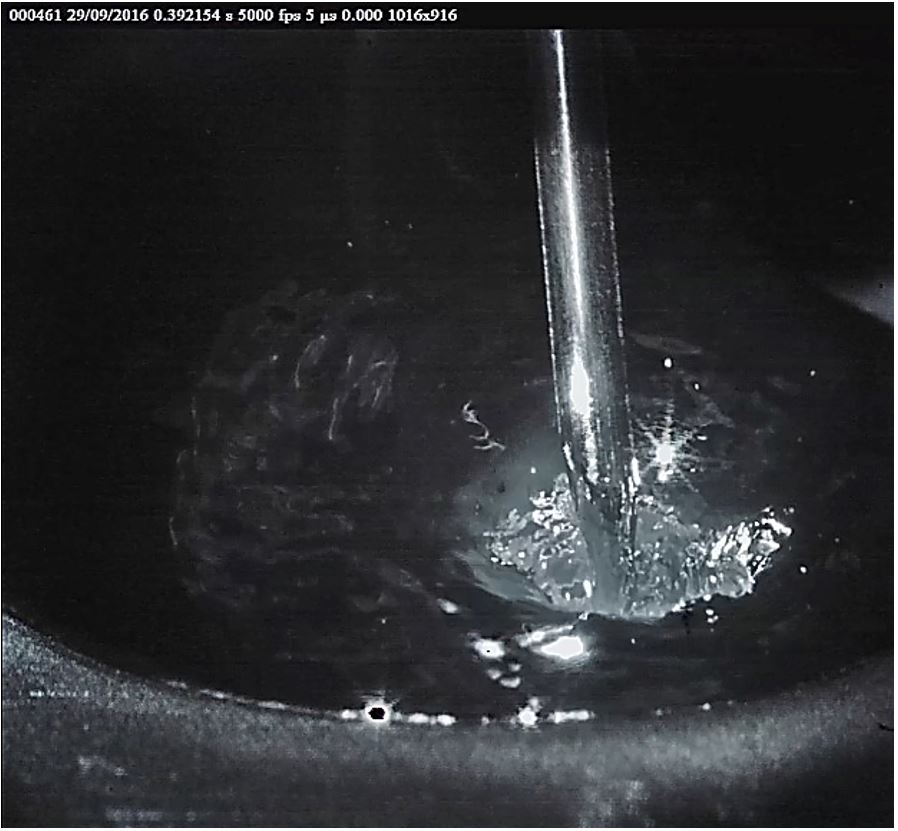
,1616 Essers WG, Walter R. Some aspects of the penetration mechanisms in metal-inert-gas (MIG) welding. In: Arc Physics and Weld Pool Behavior; 1979; London. Abington: Welding Institute; 1979. p. 289-300.]. However, there is a collateral factor that acts unfavorably in this regard, which is the inherent interdependence between the current and the wire melting rate. In other words, in order to achieve high current values, the amount of wire electrode fed to the system must be relatively high. However, too much filler metal tends to close the crater. Thus, the key point in GMAW technology, when the aim is to obtain weld profiles such as that in Figure 1, right side, is the appropriate combination of the whole set of parameters, with the welding speed being of notable importance. This needs to be properly adjusted in order to avoid a large amount of material accumulation between the arc and weld pool. The crater must be kept in the configuration shown in Figure 2, which shows images captured by high-speed filming carried out at the Mechatronics and Welding Institute, LABSOLDA, UFSC, depicting a high-penetration welding procedure in the Buried Arc mode. The strong arc pressure, caused by applying a high current, performs greater base material melting while pushing the weld pool down.

Arcing configuration acting on the surface of the molten pool and inside a crater (buried arc). Above: Butt joint and Below: Fillet joint [1111 Group EWM. MIG/MAG welding processes- force arc. 2021 [acesso em 25 maio 2021]. Disponível em: https://www.ewm-group.com/en/innovation-research/mig-mag-welding-procedure.html
https://www.ewm-group.com/en/innovation-... ].

Crater created by arc pressure on the weld pool for tests carried out under bead-on-plate conditions.
An additional point that deserves discussion in the scope of HP GMAW is the CTWD set-up. Authors state that high performance welding requires a large contact tip to workpiece distance (CTWD) [55 Matusiak J, Pfeifer T. Alternative methods of productivity increasing at MAG welding process of unalloyed steels. Hutnik, Wiadomości Hutnicze. 2008;75(3):110-115.,1717 Hudec Z. The key to efficiency of welded structures production. In: Proceedings 24th International Conference on Metallurgy and Materials; 2015; Brno, Czech Republic. Northampton: Curran Associates; 2015. p. 1828-1834.]. However, a higher CTWD increases the melting rate, which hinders the arc depth. The advantages of a high CTWD are probably related to contact tip protection and torch heating reduction, so they do not suffer severe wear due to the high arc power and the conditions remain constant, in addition to allowing better accessibility in the case of narrow joints.
As previously mentioned, the action of the arc at depth requires a combination of factors in order to keep the crater open. A metastable equilibrium is reached, in which the force created by the arc pushes the liquid metal away from arc base, avoiding crater collapse, Analog to the state reached in the TIG Keyhole technique, described in [1313 Rosellini C, Jarvis L. The Keyhole TIG welding process: a valid alternative for valuable metal joints. Welding International. 2009;23(8):616-621. http://dx.doi.org/10.1080/09507110802543237.
http://dx.doi.org/10.1080/09507110802543...
], this state relies on a complex balance among gas and metal vapor pressures, surface tension, molten pool convection and oscillation. In addition, due to the system conditions and weld pool dynamics, short circuits are intrinsic to the process. Therefore, the weld pool requires certain conditions to maintain this balance (metastable equilibrium) and deal with the occurrence of a short circuit. In addition to appropriate parameters, the welding current must respond very quickly to any event that may disrupt the metastable equilibrium. In the GMAW process, this is a function of the dynamics of the power source, which is determined by the welding circuit´s inductance. For the advanced short-circuiting metal transfer GMAW versions, this importance has been described elsewhere [1818 Dutra JC. MIG/MAG - transferência metálica por curto-circuito: fontes de soldagem versus gases do arco. Soldagem e Inspeção. 2008;13(1):19-24.
19 Souza D, Rossi ML, Keocheguerians F, Nascimento VC, Vilarinho LO, Scotti A. Influência da tensão de soldagem e do gás de proteção sobre a correlação entre indutância e regularidade da transferência metálica na soldagem MIG/MAG por curto-circuito. Soldagem e Inspeção. 2011;16(2):114-123. http://dx.doi.org/10.1590/S0104-92242011000200004.
http://dx.doi.org/10.1590/S0104-92242011...
-2020 Costa TF, Benedetti E Fo, Arevalo HDH, Vilarinho LO. Avaliação de processos MIG/MAG curto-circuito convencional e controlado para a soldagem de dutos de aço carbono em passe único. Soldagem e Inspeção. 2012;17(4):356-368. http://dx.doi.org/10.1590/S0104-92242012000400010.
http://dx.doi.org/10.1590/S0104-92242012...
]. Welding equipment manufacturers conceive solutions and announce them as determinant features in their technology. They commonly work well, although not always for the reasons and explanations given. For example, some manufacturers apply pulsed current in their technology and infer that there is metal transfer (droplet transfer) control and that this is key to the high performance achieved [2121 Baba H, Era T, Ueyama T, Tanaka M. Single pass full penetration joining for heavy plate steel using high current GMA process. Welding in the World. 2017;61(5):963-969. http://dx.doi.org/10.1007/s40194-017-0464-7.
http://dx.doi.org/10.1007/s40194-017-046...
,2222 Jaeschke B. SpeedPulse – eine produktivitäts- und effizienzsteigernde Weiterentwicklung des MSG-Impulsschweißens. Schweißen und Schneiden. 2009;61(9):548.]. In fact, current pulsing at high frequency causes a dynamic mechanical action on the physical contact between the weld pool and electrode tip, which is liquefied.
Thus, this work aims at investigating the phenomena and effects involved in high penetration GMAW welding in a deeper approach, providing clearer knowledge and technological basis for analysis and continued R&D of this promising technique.
2. Methodology
In order to verify the assertion that the pulsation itself is not the reason for obtaining the desired results, in this study a transistorized welding power source was used, operating in the conventional GMAW mode (constant voltage). One of the distinctive features of the highly flexible, open architecture power source used is that the welding current dynamics (inductance) can be adjusted during short-circuit events by the parameters ks and kd. This setting is electronic (provided by software) and enables the individual adjustment of the values related to the current upslope phase (ks) and the current downslope phase (kd). The real inductance can be calculated based on the formula in Table 1. In a series of experiments, it was found that, to maintain the metastable equilibrium, the power source reaction should be triggered rapidly at the short-circuit moment, in a highly dynamic fashion to result in an accelerated contact break [2323 Dutra JC, Gonçalves e Silva RH, Riffel KC, Marques C. High-performance GMAW process for deep penetration applications. Welding in the World. 2020;64(6):999-1009. http://dx.doi.org/10.1007/s40194-020-00889-0.
http://dx.doi.org/10.1007/s40194-020-008...
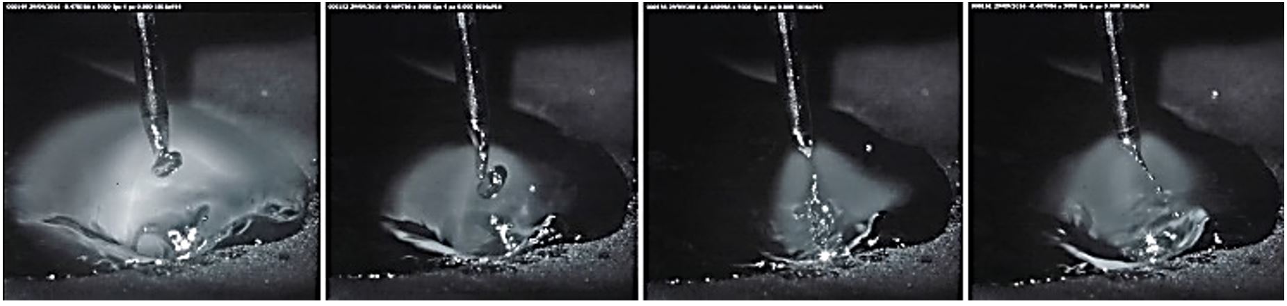
]. However, its output should not vary rapidly after the contact break, in the phase of restoration to the regime condition. An inappropriate adjustment results in events such as those shown in Figure 3, where the physical contact between the wire-electrode tip and the weld pool leads to crater closing, due to the time period being relatively long. This impairs the continuity of the deep penetration profile. An increase in spattering is also a highly likely consequence. When the inductance is set to a high reaction capacity (low inductance) at the moment of physical contact (short circuit), these tendencies are practically not observed, and the crater is maintained, as shown in Figure 2.

Crater instability during short circuiting, due to an inadequate inductance adjustment (high-speed film available on the LABSOLDA channel [2424 LABSOLDA UFSC. High Performance GMAW - Buried arc incorrect inductance for down slope (IMC DIGIPLUS A7 KS100 KD100). 2019 [access 25 may 2021]. Available from: https://youtu.be/zCr5Imyf4fM
https://youtu.be/zCr5Imyf4fM... ]).
In order to keep the process in a metastable equilibrium, to ensure stability and constant penetration, the source must react relatively rapidly after a short-circuit event and smoothly in the arc re-stabilization, provided by the flexibilization of the arc dynamics. In this context, this GMAW version was designated as a dynamically flexible arc (DynaFlex-Arc). For the welding conditions applied in this investigation, the parameterization for stability is given in Table 1.
For high speed videography, bead-on-plates on 12.7 mm thick AISI 1020 steel were welded, with a 1.2 mm diameter ER70S-6 wire-electrode and Ar+8%CO2 as shielding gas. A portable welding monitoring system (SAP) was applied for data acquisition and treatment, for oscillographic process performance analysis. The high speed camera used was the IDT Motion Pro at 5000 fps, with a CAVILUX laser illumination system.
Further tests were carried out in order to verify and validate the optimized inductance technique that characterizes the Dynamically Flexible Arc GMAW version (DynaFlex-Arc). Butt-welded joints of carbon steel plates (3/8” thick) were performed in the flat position. The wire feed speed was 15 m/min (ER 70S-6, 1.2 mm diameter) and the voltage was set at 32.5 V. Ar+25%CO2 and pure CO2 were used for these tests. The first approach was to check the process variant performance for unmachinned joints (no groove, no gap joints).
3. Results and Discussion
For the conditions applied in this study, the metal transfer takes place through a continuous filament of melted material at the wire-electrode tip, with no well-defined single droplet formation (Figure 4). The literature cites the use of pulsed current with single or multiple-drop formation during each pulse period, such as in the case of the Speed Pulse version [2222 Jaeschke B. SpeedPulse – eine produktivitäts- und effizienzsteigernde Weiterentwicklung des MSG-Impulsschweißens. Schweißen und Schneiden. 2009;61(9):548.], as well as the Rapid Arc version (Figure 5).

Crater formed in the DynaFlex-Arc GMAW process (high-speed films available on the LABSOLDA channel [2525 LABSOLDA UFSC. High Performance GMAW - Buried arc condition (IMC DIGIPLUS A7 KS100 KD1). 2019 [access 25 may 2021]. Available from: https://youtu.be/RkpVX2cv1qc
https://youtu.be/RkpVX2cv1qc... ]).

Rapid Arc metal transfer multiple-drop formation during the pulse period (high-speed films available on the LABSOLDA channel [2626 LABSOLDA UFSC. RAPID ARC® welding process under high penetration application. 2019 [access 25 may 2021]. Available from: https://youtu.be/OAD3HNoIRX4
https://youtu.be/OAD3HNoIRX4... ]).
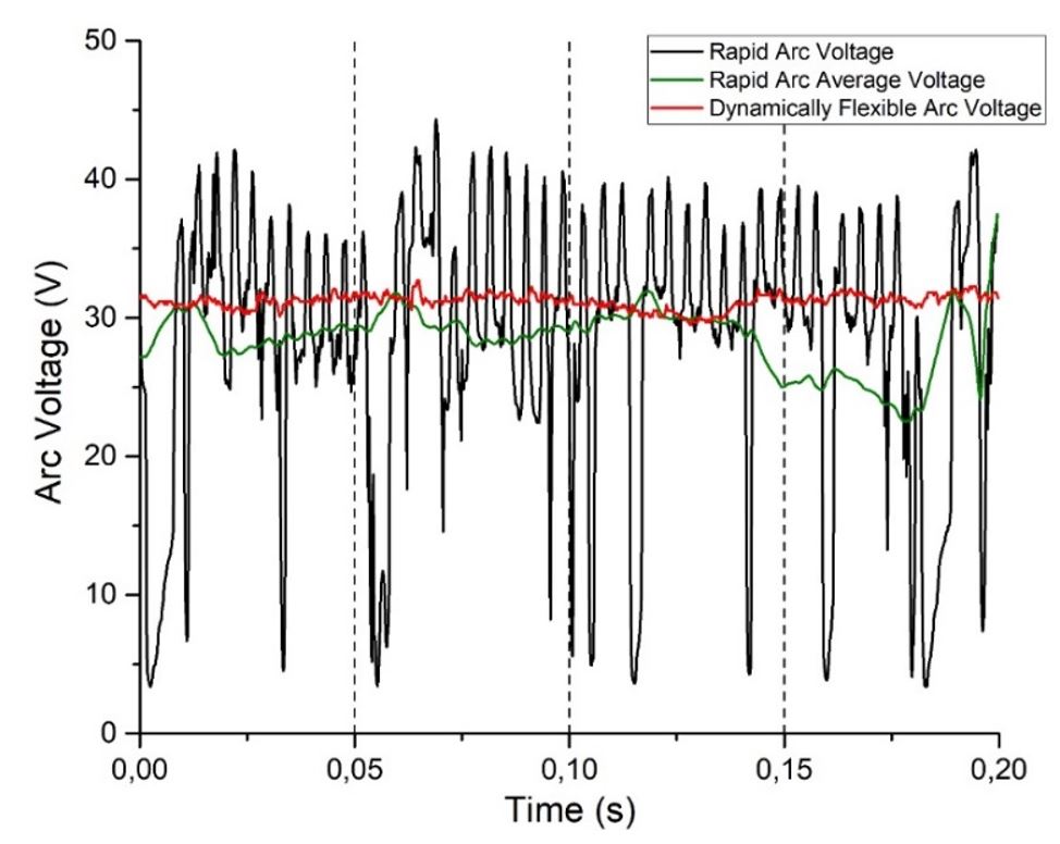
In order to compare the performance of the HP GMAW welding current modes and the respective dynamic behavior in response to short-circuit events, the current upslope for Rapid Arc GMAW versus that for the version proposed herein (DynaFlex-Arc) was analyzed. The oscillograms for the two cases can be seen in Figure 6. Although a markedly higher current dynamic was observed for the Rapid Arc, under the Buried Arc condition, the benefits mentioned with regard to penetration and weld geometry could not be established. Also, as seen in Figure 7, stability gains were not inferred by the respective voltage oscillograms (voltage dynamic behavior/regularity is an index of process stability [2727 Hemans M, Den Ouden G. Process behavior and stability in short circuit gas metal arc welding. Welding Journal. 1999;78(4):137-141.]). In fact, the oscillograms in Figure 7 and the high speed video frames in Figures 4 and 5 show a much greater impact of the short circuits on the electrical behavior (process stability) for the pulsed version. This indicates that the pulsed current mode with extra high current dynamics is not required, as this already exists in the pulsed versions for high performance welding. For satisfactory welding results, the power source features required are the ability to react promptly and appropriately (only when the metastable equilibrium is affected by a crater closing tendency due to short circuits) and to provide sufficiently rapid current dynamics for certain conditions.

Comparison of oscillograms for proposed system (DynaFlex-Arc) in response to a short-circuit event and for the Rapid Arc pulsed wave form.

The butt-weld tests indicated that achieving deep penetration is not problematic, because the molten pool and weld depth are more than sufficient, as seen in the macrographs of welds using Ar+25%CO2 and pure CO2 in Figure 8. The major issue that arises is the fact that the electric current and filler wire speed cannot be dissociated, resulting in an excessive melting rate and high bead reinforcement. The compatibility between parameters in terms of improving the bead appearance becomes a difficult issue to solve.

Butt welding macrographs with wire feed speed= 250 mm/s (15 m/min), Ts= 7.5 mm/s without a groove or root opening (gap) with support backing. (a) Ar+25%CO2, Ia= 377 A; (b) Pure CO2, Ia= 350 A.
Since the weld profiles were not entirely satisfactory due to the excess of reinforcement, a possible solution is the machining of a groove (beveling) in order to accommodate the excess of filler material. Another alternative would be to use a gap between the unmachined plates, but in a real manufacturing production system, it is very difficult to maintain small and constant gaps. Therefore, the first alternate solution was chosen for further development and analysis.
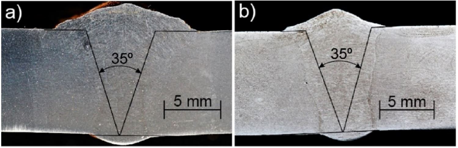
Procedure development was carried out, whose results are shown in Figure 9, which depicts macrographs for machined 35º angle V joints. Under this condition (V groove), the wire feed speed could be reduced to 217 mm/s (13 m/min), resulting in a welding current Ia of 385 A with Ar+25%CO2 (Figure 9a) and 340 A with Ar+50%CO2 (Figure 9b). The welding result with Ar+50%CO2 has a shape factor (face width/root width) close to 1 (i.e., more efficient melting, when compared to the other two mixtures).

Butt welding macrographs for 35º V groove joint, wire feed speed=217 mm/s (13 m/min), Ts= 7.5 mm/s. (a) Ar+25%CO2, Ia=385A; (b) Ar+50%CO2, I= 340 A.
4. Conclusions
For proper operational performance of the high performance GMAW version (high penetration, buried arc), the metastable equilibrium of the molten pool is maintained by means of rapid power source electrical reactions in moments of incipient short-circuiting. On arc reignition, the restoration of the welding current to its regime value should occur slowly. It appears that some equipment manufacturers are launching new power sources for the aforementioned application with the use of pulsed current, which are performing in a much more complicated (and likely more expensive) way than the physics of the welding process requires.
The results reported herein demonstrated that a power source only needs to provide dynamic characteristics sufficient to maintain the molten pool in a metastable equilibrium, in a form similar to the keyhole mode, so that the arc acts continuously at depth. Independent adjustment of the dynamic characteristics (inductance) enables optimization of the welding current upslope and downslope for distinct welding conditions. For the welding conditions of this study, the high penetration GMAW technique was enabled by a current upslope rate of 70000 A/s, while the current downslope rate was 300 A/s, a method that was called Dynamically Flexible Arc (DynaFlex-Arc or simply DynaFflex-Arc). The use of Ar+25%CO2 as the shielding gas provided better macroscopic results than Ar+8CO2.
More studies have to be carried out in order to evaluate possible benefits of the pulsed version, as more favorable bead geometry for horizontal fillet welds, for example.
Test results also led to the conclusion that, to carry out welding of thick plates in a butt-welding configuration and without a gap, groove machining is essential for accommodating the deposited filler metal, and its main purpose is not necessarily to achieve satisfactory penetration. Economically, this represents a loss, because material is wasted and secondary operations and times emerge. Nevertheless, the groove angle is low and the productivity benefits of single pass welding remain.
-
How to cite: Dutra JC, Silva RHG, Bernardi RA, Schwedersky MB, Marques C, Riffel KC. A new interpretative basis for the high performance GMAW process. Soldagem & Inspeção. 2021;26:e2620. https://doi.org/10.1590/0104-9224/SI26.20
References
-
1Merkblatt DVS. 0909-1. Grundlagen des MSG-Hochleistungsschweißens mit Massivdrahtelektroden Definitionen und Begriffe. DVS; 2000.
-
2DVS. Overview of process control variants for gas-shielded metal-arc welding. 2017. (Technical Bulletin DVS; 0973).
-
3Ribeiro BYR, Santos EBF, Assunção PDC, Maciel RR, Braga EM. Predicting weld bead geometry in the novel CW-GMAW process. Welding Journal. 2015;94:301s-311s.
-
4Auenwald BJ, Vollrath K. SpeedPulse – eine produktivitats- und effizienzsteigernde weiterentwicklung des MSG-Impulsschweißens. Schweißen und Schneiden. 2009;61(9).
-
5Matusiak J, Pfeifer T. Alternative methods of productivity increasing at MAG welding process of unalloyed steels. Hutnik, Wiadomości Hutnicze. 2008;75(3):110-115.
-
6Bengtsson P, Skarin D. High speed welding with the A400 HSW robot system and the Rapid Arc™ and Rapid Melt™ processes. Svetsaren. 1992;46(2):26-31.
-
7Church G, Imaizumi H. Welding characteristics of a new welding process. Villepinte: International Institute of Welding; 1990. TI.M.E. Process. Doc.IIW com.XII-1199-90.
-
8Stenke V, Lahnsteiner R, Schoenberger H. The TI.M.E. Process – Characteristics of a new GMAW Technology. Villepinte: International Institute of Welding; 1991. Doc. IIW com. XXI-1233-91.
-
9Lahnsteiner R. The TI.M.E. process: an innovative MAG welding process. Welding Review International. 1992;11:17-20.
-
10Stol I, Williams KL, Gaydos DW. Back to basics: using a buried gas metal arc for seam welds. Welding Journal. 2006;4.
-
11Group EWM. MIG/MAG welding processes- force arc. 2021 [acesso em 25 maio 2021]. Disponível em: https://www.ewm-group.com/en/innovation-research/mig-mag-welding-procedure.html
» https://www.ewm-group.com/en/innovation-research/mig-mag-welding-procedure.html -
12Schwedersky MB, Gonçalves e Silva RH, Dutra JC, Reisgen U, Willms K. Two-dimensional arc stagnation pressure measurements for the double-electrode GTAW process. Science and Technology of Welding and Joining. 2016;21(4):275-280. http://dx.doi.org/10.1080/13621718.2015.1104095
» http://dx.doi.org/10.1080/13621718.2015.1104095 -
13Rosellini C, Jarvis L. The Keyhole TIG welding process: a valid alternative for valuable metal joints. Welding International. 2009;23(8):616-621. http://dx.doi.org/10.1080/09507110802543237
» http://dx.doi.org/10.1080/09507110802543237 -
14González Olivares EA, Gonçalves e Silva RH, Dutra JC. Study of keyhole TIG welding by comparative analysis of two high-productivity torches for joining medium-thickness carbon steel plates. Welding International. 2017;31(5):337-347. http://dx.doi.org/10.1080/09507116.2016.1218603
» http://dx.doi.org/10.1080/09507116.2016.1218603 -
15Scotti A, Rodrigues CEAL. Determination of the momentum of droplets impinging on the pool during aluminium GMAW. Soldagem e Inspeção. 2009;14(4):336-343. http://dx.doi.org/10.1590/S0104-92242009000400008
» http://dx.doi.org/10.1590/S0104-92242009000400008 -
16Essers WG, Walter R. Some aspects of the penetration mechanisms in metal-inert-gas (MIG) welding. In: Arc Physics and Weld Pool Behavior; 1979; London. Abington: Welding Institute; 1979. p. 289-300.
-
17Hudec Z. The key to efficiency of welded structures production. In: Proceedings 24th International Conference on Metallurgy and Materials; 2015; Brno, Czech Republic. Northampton: Curran Associates; 2015. p. 1828-1834.
-
18Dutra JC. MIG/MAG - transferência metálica por curto-circuito: fontes de soldagem versus gases do arco. Soldagem e Inspeção. 2008;13(1):19-24.
-
19Souza D, Rossi ML, Keocheguerians F, Nascimento VC, Vilarinho LO, Scotti A. Influência da tensão de soldagem e do gás de proteção sobre a correlação entre indutância e regularidade da transferência metálica na soldagem MIG/MAG por curto-circuito. Soldagem e Inspeção. 2011;16(2):114-123. http://dx.doi.org/10.1590/S0104-92242011000200004
» http://dx.doi.org/10.1590/S0104-92242011000200004 -
20Costa TF, Benedetti E Fo, Arevalo HDH, Vilarinho LO. Avaliação de processos MIG/MAG curto-circuito convencional e controlado para a soldagem de dutos de aço carbono em passe único. Soldagem e Inspeção. 2012;17(4):356-368. http://dx.doi.org/10.1590/S0104-92242012000400010
» http://dx.doi.org/10.1590/S0104-92242012000400010 -
21Baba H, Era T, Ueyama T, Tanaka M. Single pass full penetration joining for heavy plate steel using high current GMA process. Welding in the World. 2017;61(5):963-969. http://dx.doi.org/10.1007/s40194-017-0464-7
» http://dx.doi.org/10.1007/s40194-017-0464-7 -
22Jaeschke B. SpeedPulse – eine produktivitäts- und effizienzsteigernde Weiterentwicklung des MSG-Impulsschweißens. Schweißen und Schneiden. 2009;61(9):548.
-
23Dutra JC, Gonçalves e Silva RH, Riffel KC, Marques C. High-performance GMAW process for deep penetration applications. Welding in the World. 2020;64(6):999-1009. http://dx.doi.org/10.1007/s40194-020-00889-0
» http://dx.doi.org/10.1007/s40194-020-00889-0 -
24LABSOLDA UFSC. High Performance GMAW - Buried arc incorrect inductance for down slope (IMC DIGIPLUS A7 KS100 KD100). 2019 [access 25 may 2021]. Available from: https://youtu.be/zCr5Imyf4fM
» https://youtu.be/zCr5Imyf4fM -
25LABSOLDA UFSC. High Performance GMAW - Buried arc condition (IMC DIGIPLUS A7 KS100 KD1). 2019 [access 25 may 2021]. Available from: https://youtu.be/RkpVX2cv1qc
» https://youtu.be/RkpVX2cv1qc -
26LABSOLDA UFSC. RAPID ARC® welding process under high penetration application. 2019 [access 25 may 2021]. Available from: https://youtu.be/OAD3HNoIRX4
» https://youtu.be/OAD3HNoIRX4 -
27Hemans M, Den Ouden G. Process behavior and stability in short circuit gas metal arc welding. Welding Journal. 1999;78(4):137-141.
Publication Dates
-
Publication in this collection
05 Jan 2022 -
Date of issue
2021
History
-
Received
25 May 2021 -
Accepted
27 Aug 2021