Abstracts
Metal-ceramic joining has slowly but steadily become an important manufacturing step. The evolution of joining processes has allowed ceramics to be used in combination with metals in a number of hybrid devices from traditional light bulbs and seals to improved cutting tools and modern monitoring and measuring electronic devices. New joining methods and newer approaches to conventional methods have been developed aiming at joints characterized by improved reliability, and interfaces capable of withstanding high-temperature resistance with minimum residual stresses. A summary of recent improvements on alternative approaches to ceramic-metal joining as well as new developments on brazing are presented herein. The present review also focuses on recent advances towards brazing metallized ceramics and the selection of filler alloys, since in a scenario that includes joining by laser and direct bonding with liquid transient phases, brazing continues to be by far the most widely used approach to joining as a result of its low-cost and possibility to join intricate geometries for large-scale production. Finally, methods to evaluate the mechanical strength and residual thermal stresses are presented in addition to alternative approaches to minimize residual stresses and, consequently, improve joint reliability.
ceramic-metal joining; structural ceramics; brazing; metallization; titanium coating
O interesse no estudo de métodos de junção-cerâmica para aplicações industriais tem crescido gradativamente ao longo dos anos. A evolução dos processos de união tem permitido a utilização de cerâmicas em conjunto com metais na fabricação de diversos componentes híbridos incluindo lâmpadas tradicionais, juntas para vácuo, ferramentas de corte de alto desempenho e modernos dispositivos eletrônicos de medição e monitoramento. Novos métodos de união e aprimoramentos de métodos convencionais têm sido estudados com o intuito de produzir-se juntas com alta confiabilidade e interfaces capazes de suportar altas temperaturas de trabalho com o mínimo de tensões residuais. O presente trabalho apresenta um panorama dos recentes avanços em técnicas alternativas de união, incluindo união por laser e junção direta com fases líquidas transientes. Além disso, apresenta-se uma discussão sobre novas tendências em brasagem de cerâmicas metalizadas e seleção de ligas de adição, já que este processo continua sendo amplamente utilizado por seu baixo custo de fabricação de grandes lotes de peças. Por fim, métodos de análise de resistência mecânica e tensões residuais são apresentados juntamente com alternativas para melhoria de confiabilidade de juntas por meio da redução de tensões.
junção cerâmica-metal; cerâmicas estruturais; brasagem; metalização; revestimento de titânio
Review Article: Recent advances in metal-ceramic brazing
Artigo Revisão: Avanços recentes em brasagem metal-cerâmica
R. M. do NascimentoI; A. E. MartinelliI; A. J. A. BuschinelliII
IDepartamento de Engenharia Mecânica, Universidade Federal do Rio Grande do Norte, Campus Lagoa Nova, Natal, RN, 59072-970, rubens@dem.ufrn.br, aemart@uol.com.br IIDepartamento de Engenharia Mecânica, Laboratório de Soldagem, Universidade Federal de Santa Catarina, Campus Universitário Trindade, Florianópolis SC, 88040-900, buschi@emc.ufsc.br
ABSTRACT
Metal-ceramic joining has slowly but steadily become an important manufacturing step. The evolution of joining processes has allowed ceramics to be used in combination with metals in a number of hybrid devices from traditional light bulbs and seals to improved cutting tools and modern monitoring and measuring electronic devices. New joining methods and newer approaches to conventional methods have been developed aiming at joints characterized by improved reliability, and interfaces capable of withstanding high-temperature resistance with minimum residual stresses. A summary of recent improvements on alternative approaches to ceramic-metal joining as well as new developments on brazing are presented herein. The present review also focuses on recent advances towards brazing metallized ceramics and the selection of filler alloys, since in a scenario that includes joining by laser and direct bonding with liquid transient phases, brazing continues to be by far the most widely used approach to joining as a result of its low-cost and possibility to join intricate geometries for large-scale production. Finally, methods to evaluate the mechanical strength and residual thermal stresses are presented in addition to alternative approaches to minimize residual stresses and, consequently, improve joint reliability.
Keywords: ceramic-metal joining, structural ceramics, brazing, metallization, titanium coating.
RESUMO
O interesse no estudo de métodos de junção-cerâmica para aplicações industriais tem crescido gradativamente ao longo dos anos. A evolução dos processos de união tem permitido a utilização de cerâmicas em conjunto com metais na fabricação de diversos componentes híbridos incluindo lâmpadas tradicionais, juntas para vácuo, ferramentas de corte de alto desempenho e modernos dispositivos eletrônicos de medição e monitoramento. Novos métodos de união e aprimoramentos de métodos convencionais têm sido estudados com o intuito de produzir-se juntas com alta confiabilidade e interfaces capazes de suportar altas temperaturas de trabalho com o mínimo de tensões residuais. O presente trabalho apresenta um panorama dos recentes avanços em técnicas alternativas de união, incluindo união por laser e junção direta com fases líquidas transientes. Além disso, apresenta-se uma discussão sobre novas tendências em brasagem de cerâmicas metalizadas e seleção de ligas de adição, já que este processo continua sendo amplamente utilizado por seu baixo custo de fabricação de grandes lotes de peças. Por fim, métodos de análise de resistência mecânica e tensões residuais são apresentados juntamente com alternativas para melhoria de confiabilidade de juntas por meio da redução de tensões.
Palavras-chave: junção cerâmica-metal, cerâmicas estruturais, brasagem, metalização, revestimento de titânio.
JOINING PROCESSES
Advanced ceramics are relatively new materials that slowly but steadily have been used in an increasing number of applications, especially as structural materials. Nevertheless, designing and engineering ceramic structures require additional attention to the development of elevated tensile stresses, which could result in component failure. As responses to their predominantly covalent nature, advanced ceramics are hard lightweight materials capable of withstanding severe abrasion and maintaining chemical inertness at elevated temperatures. Reducing weight and increasing operating temperatures are goals of combustion engines and turbine manufacturers aiming at increased payload and improved thermodynamic efficiency to energy conversion [1-4]. Examples of ceramic parts used in turbines and engines are illustrated in Fig. 1. On the other hand, hard covalent materials exhibit serious drawbacks, i.e., they are brittle are difficult to machine [3, 5, 6]. These limits have been overcome by developing ceramic strengthening mechanisms and limiting the application of ceramics to small critical components.
For the former approach, different routes from improving composites to tailoring of microstructures have been employed. The latter methodology basically involves the use of small parts made of monolithic ceramics joined together to structural metals. Joining dissimilar materials has been long investigated not only for ceramic-metal, but also for a number of other combinations such as glass/metal and glass-ceramic/metal. Glass/metal joining, for example, dates back to the invention of the electric light bulb in the early 1800 s. Construction of the device depended on joining a glass bulb to a metal to close an electric contact. This type of joint was improved between 1950 and 1970 and is now largely employed in the electronic industry as well as in the manufacture of medical equipment (heart pacemakers and insulin pumps) and weaponry. Replacing glasses by glass-ceramics improves joining reliability due to their improved resistance and toughness. The thermal expansion of glass-ceramics and metals are also closer-matched as compared to metal and conventional glasses [7].
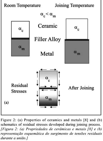
Most of the time, joining different materials is not an easy task. Atoms, ions, or molecules in materials of different classes - ceramics, metals, or polymers - are joined together in different ways, and therefore characterized by particular combinations of physical-chemical and mechanical properties. Joining dissimilar materials implies in property mismatches and structure discontinuities, which must be accounted for and minimized. For instance, brazing ceramics relies on wetting (spreading) of the ceramic surface by some kind of metal, which is often hindered by the covalent nature of the ceramics. Once a suitable interlayer (metal coating) or metal alloys wet and react with the ceramic, which can then be bonded to its counterpart, e.g., a metal. The vast majority of joining processes involves heating of the couple. Upon cooling of the joint, mismatches in elastic modulus and thermal expansion coefficient (Fig. 2a) often result in the development of residual stresses deleterious to the mechanical soundness of the joint (Fig. 2b). Ceramics with limited fracture toughness interface often rupture under the effect of such stresses. The key to a successful joint with dissimilar counterparts is the design of buffer interfaces capable of accommodating materials dissimilarities originated from different chemical bonds and properties [8-11].

The evolution of joining processes has allowed ceramics to be used in combination with metals in the manufacture of a growing number of hybrid devices from the traditional electric light bulb to improved cutting tools and modern monitoring and measuring electronic devices [7]. Joining has become an important manufacturing step. A variety of metal-ceramic joining processes, whose use mainly depend on the base materials to be bonded and the application of the joined component, are either currently available or under development. Ceramics and metals can be joined together by mechanical, direct, or indirect processes (Fig. 3) [5, 10].
Mechanical joining encompasses simple and cost-efficient processes such as screwing, fastening, clamping, and shrink fitting. Typical mechanical strengths of the joints vary from 10 to 50 MPa. Stress concentration areas (especially in the ceramic counterpart) and design limitation are among the major restrictions of those methods [5, 10, 12].
Indirect and direct joining refers to the use or not of an intermediate material (such as a filler alloy) to promote physical or chemical bonding between counterparts. Charge or mass transfer can take place in either case [5]. Solid-state diffusion is a well-known example of a direct ceramic-to-metal joining process. Close tolerances and high mechanical strengths (100 1000 MPa) are usually attained. In addition to that, admissible working temperatures are imposed by the base materials instead of the interface. Temperatures in excess of 1000 ºC are often possible for SiC-, Si3N4- and Al2O3-metal joints. Stresses are attenuated by optimizing joint geometry and using a variety of interlayers such as refractory metals or functionally graded materials (FGM) [13]. Hot-pressing or hot-isostatic pressing (HIPing) are batch processes normally used to produce planar joints [5, 10, 14, 15]. Friction welding is another example of solid state joining (Fig. 4). Application in ceramic-metal joining is still in its early stages of development. Successful ZrO2/aluminum alloys joints have been reported [16]. Firstly, one of the joining surfaces is rotated, the joining surfaces are slightly pressured together and frictioned against each other, resulting in enough heating and joining of the couple. The relative movement is then interrupted and the normal force is increased. The process can be carried out using conventional friction welding apparatus but under a protective atmosphere to avoid metal oxidation. The components to be joined (especially the ceramic) must be planar and parallel to avoid crack formation and propagation as well as joining imperfections. These defects can be originated from uneven heating of non-parallel surfaces. Finally, fusion welding is a direct joining method based on the localized melting of the metallic component. A laser beam is commonly used as heating source. The resulting joints normally reach mechanical strengths between 50 and 200 MPa at temperatures in excess of 1000 ºC (depending on the base materials). On the downside, grain growth and residual stress development may also occur [17-20].
Joining processes which require the use of filler materials, such as adhesive joining and brazing, are commonly referred to as indirect joining processes. Adhesive joining using organic interlayers offers suitable mechanical strength below 250 ºC (Table I). Glassy interlayers can also be used to improve high-temperature resistance. Examples of adhesive joining include magnetic ceramics in electric motors as well as ceramic lining to oil ducts. In the latter case, ceramics are used as a protective barrier against corrosion of wear. Glassy interlayers have been long used to join Al2O3 to Nb in sodium vapor light bulbs [5, 7, 10]. Brazed joints can be used in devices subjected to temperatures as high as 500 ºC with moderate mechanical strength (~ 100 MPa) [5, 8, 10]. Structural ceramics such as Si3N4, SiC, Al2O3, AlN and ZrO2 have been brazed to a number of structural metals and alloys [21, 22]. New and improved filler alloys have been extensively studied aiming at lowering joining costs and producing refractory joints [21-25].
New joining methods and newer approaches to conventional methods have been developed over the years aiming at improved reliability. The availability of reliable ceramic/ceramic and ceramic/metal joining processes and its effect on the expansion of the structural ceramics market to large scale use is a quite established concept by now [21, 26- 28]. Broadening the use of joining technology to new devices as well as improving joining to specific applications have always been the major goals [18, 21, 23, 26]. Recent improvements on ceramic rotor technology and their systematic use to reduce consumption and pollutant emission of Japanese automobiles have driven forward metal-ceramic joining and resulted in significant technological and scientific advances. Traditionally, shrink fitting and brazed have been used to join Si3N4 rotors to metallic shafts [29, 30]. On a more recent joint design, the ceramic rotor was shrink fitted to a metallic sleeve which was then friction welded to the shaft, resulting in improved bearing cooling and reduced residual stresses [31, 32].
Novel ceramic/metal joining techniques are in constant development. Diffusion bonding with the formation of transient liquid phases and direct joining of metals to ceramics using laser are some of the most recent advances [18, 26]. Nevertheless, brazing is by far the most widely used joining process when mechanically reliable vacuum tight joints are required to operate at relatively high temperatures. Brazing allows low-cost large-scale joining of intricate geometries and is not necessarily restricted to flat surfaces. The main advanced structural ceramics, i.e., SiC, Si3N4, and Al2O3 have been brazed to a variety of metals and steels of engineering interest [5, 10, 12, 15, 33, 34]. Some examples are shown in Table II [8, 12]
Brazing has been defined by the American Welding Society (AWS) as a joining process that takes place above 450 ºC using filler metals or alloys which flows by capillary forces and whose melting temperature is lower than the solidus temperature of the base materials. Filler metals or alloys should adhere to the surface of the base materials [35-38]. The German standard DIN 8505 classifies brazing into three categories, i.e, soft (or soldering), hard, and high-temperature brazing (Fig. 5). The criterion takes into account the process temperature, the type of filler alloy, the use of fluxes and the brazing atmosphere [16, 39, 40]. By soft brazing it is possible to minimize thermal deformations because of the typical low process temperatures. Joining couples can be heated using resistive or induction furnaces, ultrasound or flame. Pb- or Zn-based filler alloys are mostly used along with fluxes in order to prevent oxidation and improve wetting of the substrate [37, 39, 40]. Soft brazing is not commonly used in ceramic/metal joining. Hard brazing can be carried out with the use of fluxes or not. Brazing atmospheres can be vacuum, reducing or inert gases, or even air. Heating sources such as those mentioned for soft brazing can be used. Laser and electron beam heating can also be applied. High-temperature brazing is normally carried out under protective atmosphere or vacuum [16, 37, 39, 40].
Filler alloys are also classified into two categories: active and non-active. Active filler alloys include the presence of an active element, such as Ti or Nb in its composition. Non-active filler alloys are significantly cheaper but require prior metallization of the ceramic substrate to grant enough wetting so an interface (usually reactive) is formed. Active filler alloys for direct ceramic/metal brazing should depict some essential features in order to improve interfacial microstructure, such as [35, 41-43]:
1. Melting point or melting range compatible with those of the base materials;
2. Moderated fluidity at the brazing temperature, promoting capilarity and uniform distribution over the joint but preventing infiltration into sintered base materials (both metals and ceramics);
3. Homogeneous composition and stability to minimize constituent separation or segregation upon melting and solidification (brazing cycle);
4. Thermodynamic compatibility with the base metal surfaces promoting wetting;
5. Limited trend to brittle phase formation (usually intermetallics) and
6. Compatibility with the working temperature, mechanical loading, environment, and intended life span for the joint.
Active-metal filler alloys used to braze ceramics usually melt between 700 ºC and 1000 ºC. They can be classified according to their composition into two major groups: Cu-X and Ag-Cu-X alloys. The active component of the system (X) is commonly an element of the IVB group of the periodic table (Ti, Zr, Hf) which can be used in combination with other elements (Ni, Be, V, Sn, or In) to adjust the alloy behavior, e.g., improve the activity of the element, reduce melting temperature, increase alloy fluidity [15, 44, 45]. The reduced solubility of Ti in Ag, for example, acts towards increasing the activity of Ti in the alloy. Therefore, small contents of Ti considerably improve wetting of ceramic substrates. Moreover, Ti is highly soluble in Cu, which on its turn forms an eutectic with Ag, hence attenuating the activity of Ti. This combination of features is used to produce rather functional Ag-Cu-Ti alloys for ceramic/metal brazing [15, 42, 45, 46]. Other Cu-based filler alloys include active metals such as Au, Ni, Cr, Mo, V, and Pd and melt at relatively higher temperatures (~ 1000 ºC) [21, 24]. Table III summarizes the chemical composition along with the solidus and liquidus temperatures of widely used commercial filler alloys [21, 26, 47-51].
The present review reports on the basic aspects, major concerns and new trends on brazing of advanced oxide and non-oxide ceramics to metals such as low-expansion alloys and stainless steels. Wetting, metallization, common brazed joints, and mechanical behavior and residual stress evaluation will be discussed in some detail.
WETTING AND ADHESION
Joining two materials together requires the establishment of an interface where bonding occurs. The nature of this interaction can be chemical, physical, or simply mechanical. Joining processes resulting in physical or chemical bonding, such as solid-state diffusion and brazing, are ruled by the general thermodynamic principle of energy reduction: the elimination of two surfaces to form an interface reduces the total energy of the system. When the materials to be joined are dissimilar, there also exists a chemical potential gradient at the interface [52]. Ceramic/metal brazing relies on the ability of a filler metal or alloy to wet the ceramic surface. Whether a liquid wets or not a solid surface depends on the magnitude of the surface tensions and the reactivity of the species involved [46, 53, 54]. Surface properties, microstructure of the ceramic material, and reactivity of the filler alloy with the ceramic in the brazing atmosphere are the main aspects that control wetting [54]. Wetting can be either physical or chemical, depending on the nature of the bonding established between solid and liquid. Physical wetting occurs when reversible Van der Waals forces act at the interface level. Chemical wetting occurs when chemical reactions between solid and liquid take place, resulting in strong bonds responsible for wetting. Physical and chemical wetting differ on the magnitude of the bonding energy, 1 - 10 J/mol for the former, and 10 - 100 J/mol for the latter [53, 54].
The total free energy of a system can be expressed as

where A is the interfacial area and g is the free energy per unit area, i.e., the excess energy due to the presence of an interface. Gº is the free energy of the system assuming that the surface and bulk properties of the material are identical. For a liquid-vapor interface at constant pressure and temperature, the surface containing free energy g (J/m2, SI units) exerts a surface tension s (N/m, SI units) on the liquid. The term surface is applied to an area formed between a condensed (solid or liquid) and a gaseous phase. Interface refers to systems involving only condensed phases. The energy and reactivity of atoms and molecules forming surfaces or interfaces is significantly higher than those of the constituents of the bulk material. This stored energy is referred to as the interfacial or superficial energy [54-56]. The tension produced on liquid/vapor interfacial atoms or molecules as a result of unbalanced repulsive and attractive forces is interpreted as surface tension [56]. The concept of surface energy is also associated with solid surfaces. However, it cannot be measured using the same techniques applied to liquids. The surface energy of solid surfaces is difficult to be quantified and theoretically interpreted. For interfaces involving solids, it is not clear that the interfacial energy, g, depends on the area, and consequently, the free energy and surface tension are not identical [54].
Non-reactive wetting
The magnitude of wetting of a solid surface by a liquid can be evaluated from the contact angle, q, defined by Young's equation [53-55, 57, 58]:

where gsv is the solid-vapor (air), gsl is the solid-liquid and glv is the liquid-vapor interfacial energies. The thermodynamic balance between interfacial energies represented by surface tensions is schematically shown in Fig. 6. The contact angle determines wetting (q < 90º) and non-wetting (q > 90º) conditions. From a practical standpoint, wetting is assumed when (q < 70º) [57]. Wetting thus takes place [54]. Equation (A) is valid under thermodynamic equilibrium conditions and considering that no adsorption takes place at the interface. Moreover, it should be noted that the values of surface tension correspond to areas far from the contact line [53, 54, 59, 60]. Young's equation refers only to equilibrium on the horizontal direction. On the normal direction, glv.sen(q) is balanced by the reaction force of the substrate. The deformation of the surface of the solid is irrelevant [54, 56].
In non-reactive conditions, wetting is represented by a stationary contact angle, and depends only on the physical properties of the materials involved. The thermodynamic condition for wetting to occur is expressed by gsv>gsl>glv. . Conversely, wetting does not take place when gsv<gsl<glv. The driving force, F, for non-reactive wetting can be written as:

where q(t) is the instantaneous contact angle.
Non-reactive wetting is considered under thermodynamic equilibrium which can be reached after a few seconds or several minutes [54, 61]. Thermodynamic equilibrium requires the chemical potential of each component to be equal at the temperature and pressure of each phase. The total free energy of a solid-liquid-vapor system in equilibrium can then be mathematically expressed as a function of the existent phases, their chemical potentials, m, the number of moles, n, of each component in each phase, and the interfacial area, A. Furthermore, the interface tensions should not depend on the orientation and pressure and temperature should be constant. Finally, applying the condition for thermodynamic equilibrium of the system, i.e., dG = 0 and safely assuming that the mass variation does not depend on the interfacial area, the general equation can be simplified and didactically divided into two parts that represent the mechanical and chemical equilibrium of the system [54]. Taking into consideration the condition of chemical equilibrium and that the liquid metal shapes into a small sphere, a solid/liquid interface is formed between a drop and a planar surface if total DG < 0. The driving force to increase the solid/liquid interface is then expressed by

In a non-reactive system under equilibrium, the final shape of the liquid metal drop is determined only by the mechanical equilibrium. Hence, changes in the free energy of the system are associated exclusively to variations in the surface area. An analysis of the shape of the drop as a function of the contact angle and interfacial area (Fig. 6) suggests that equation (D) can be simplified, and written in terms of drop height:

Equation (E) shows that as the free energy variation as a function of drop height is less than zero (dG/dh < 0), the solid/liquid interface area increases and the contact angle decreases until the minimum energy condition (dG/dh = 0) is reached [54, 62]. The previous argument does not take into consideration the effect of the gravitational force on the liquid drop [54, 63].
Reactive wetting
When the condition for chemical equilibrium is not satisfied, solid, liquid and vapor phases react with each other in attempt to take the system to equilibrium. Under these conditions, the interfacial energies and the contact angle vary according to the kinetics of the undergoing chemical reaction. Recent studies have focused on the kinetics of wetting and spreading of reactive systems using both theoretical models and numerical analysis. The assumptions are based on molecular dynamics and experimental results from high-resolution electronic microscopy [59, 61, 64].
A clear and unambiguous definition for the wetting driving force is still not available for solid/liquid reactive systems. A number of hypotheses along with theoretical and experimental results have been proposed though [54, 62, 64]. A simple and consistent alternative to the question is to add to equation (C) (for non-reactive systems) an additional term representing the variation in the Gibbs free energy per unit area, DGr, for the reactions that take place near the solid/liquid interface [64]

DGr(t), however, cannot be easily figured out, since the circumstances that correlate the extent of the interfacial reaction to wetting kinetics are not established. Calculations performed so far yielded only a rough estimate of DGr [64].
The reactions that can take place between solid and liquid can be classified into four major categories according to the extent of saturation of the phases involved, such as [65]:
a) Reactions where only the solid phase is not saturated with the constituents of the liquid phase;
b) Reactions where only the liquid phase is not saturated with the constituents of the solid phase;
c) Reactions with no saturation of the solid phase with respect to the liquid phase or the other way around and
d) Reactions with the formation of interfacial compounds.
In describing reactive wetting it is important to introduce the concept of dynamic surface tension, gdin, corresponding to the surface tension at the moment of the creation of a new surface. gdin is different from the tension under equilibrium, g, which can be attained after a fraction of a second or several hours [54, 56].
Fig. 7 schematically shows the different stages of reactive wetting for the case where only the solid is not saturated with the constituents of the liquid. In the first condition (represented by the sequence I-II-III-IV), the growth rate of the reaction product is less than the spreading rate of the liquid drop. This scenario changes in the second condition (represented by the sequence I-II'-III'-IV). At t0 (I) no reaction occurred and the situation is described by Young's equilibrium equation (B). As the reaction starts (t1), gsldin decreases. At this point, the liquid at the periphery of the drop is in contact with the solid substrate, which has not yet reacted and the interfacial energy, gsv, remains constant (II). The diffusion of the constituents of the reaction product continues until the reaction zone reaches the liquid drop. Both solid/liquid and solid/vapor interfacial energies decrease to DGr (III) and the system moves toward its thermodynamic equilibrium condition (IV) [54, 56, 60]. In case the diffusion rate of the reaction product constituents is higher than the spreading rate of the liquid drop (I-II'-III'-IV), gsl and gsv reduce to DGr starting at t1 (II') and the equilibrium is reached faster [54, 56, 60].
If the liquid is not initially (at t0) saturated with respect to the solid (reaction b), Young's equation applies. Following the beginning of the reaction, the composition of the liquid at the periphery of the drop rapidly tends to that of the equilibrium condition. gsl and glv are then reduced by the free energy of the reaction. During the initial stages of reaction, the contact angle decreases until the interfacial energies reach equilibrium [54, 56, 60]. Reactions classified above as (c) behave similarly to classes (a) or (b), depending on which component is saturated with respect to the other. Reactions (d) are associated with the formation of interfacial compounds and should behave just like reactions (a) [54].
Wetting experiments should reproduce the brazing conditions, i.e., atmosphere and heating cycle. Brazing is usually carried out under vacuum at least 20 ºC above the melting temperature of the brazing alloy.
Spreading and Adhesion
Understanding the mechanisms that rule spreading of a liquid over a solid surface involves thermodynamic notions (glv, gsv, gsl) and fluid mechanics theory. In the thermodynamic approach, the viscosity of the liquid is assumed to be constant. Disregarding gravitational effects, spreading becomes a function only of the interfacial energies involved [56, 60]. The spreading coefficient, S, is a parameter defined to indicate this trend

S > 0 suggests that its is energetically possible for a liquid to spread over a solid surface [54, 58-60, 66]. Microscopic analyses suggested that spreading is controlled by atomic mechanisms which occur at the triple line (solid/liquid/vapor interface), such as adsorption and desorption, surface diffusion, evaporation and condensation, molecular reorientation and viscoelastic deformation. It is believed that adsorption of the reactive element of the filler alloy by oxygen reduces the contact angle and controls wetting. At this stage, reaction products are not observed at the interface [59].
Work of adhesion, Wad, is a thermodynamic parameter related to the level of interaction between surfaces in contact. Considering a simple case where an interface between two materials such as a ceramic and a filler alloy is established only chemical bonding (no reaction product is formed), Wad can be interpreted as the work per unit area necessary to break the interfacial bonds and create two surfaces without plastic deformation of the base materials [67, 68]. Wad can be estimated measuring the contact angle between the surfaces and inputting it in the expression [67, 68]:

By rearranging equations (B) and (H) it is possible to establish a direct correlation between work of adhesion and interfacial energy

Equation (I) reveals that the lower the interfacial energy, gsl, the higher the work of adhesion, Wad, which strengthens bonding between ceramic and metal and results in adherent joints (Fig. 8) [67, 68].
Structural ceramics are tightly bonded electronically stable materials. The interaction between liquid metals and solid ceramics is only possible after partial or complete dissociation of atomic bonds [54]. Oxide ceramic surfaces are predominantly ionic and composed of anions. They depict severe charge discontinuity and high electronic bonding force. The interaction between oxide ceramics and liquid metals is ruled by the interaction between metal atoms and ceramic anions [54, 68]. Wetting a ceramic oxide depends on the affinity of the liquid metal with oxygen. Reactive metals such as Ti, Zr, Si, Al and Li completely spread onto the most common structural ceramics, i.e., Al2O3, ZrO2, TiO2, SiO2 and MgO [54].
Non-oxide covalent ceramics such as diamond, Si3N4, SiC, and BN, among others, are also characterized by stable electronic configurations and strong bonding. Wetting by a liquid metal also requires interfacial chemical reaction and, therefore, dissociation of the solid. Filler alloys to that purpose usually contain transition metals such as W, Fe, Ti, or Ta, whose affinity for the ceramic ions is rather high [54]. Table IV lists contact angles between common ceramic/filler alloy systems, illustrating the effect of the reactive element on ceramic wetting.
Knowledge of the thermodynamics and kinetics of interfacial processes is of ultimate importance in brazing materials with dissimilar characteristics, such as ceramics and metals. Both scientific and technological concepts are employed to grant enough wetting of the ceramic surface necessary to produce sound joints. Addition of small contents of a reactive element into a conventional brazing alloy usually improves wetting of ceramic substrates by diffusion of involved species and chemical reactions (direct brazing). [70]. Alternatively, the surface energy, gsv, of a ceramic substrate can be increased by metallization (indirect brazing). The next section addresses metallization methods and recent advances.
METALLIZATION OF CERAMICS
Brazing and Metallization
Ceramic/metal brazing and metallization are intimately related, since metallized ceramics can be brazed to metals without active filler alloys at reduced costs [71-73]. Metallization processes have been long studied and several of them are now available. The choice of a suitable metallization technique should take into account the base materials involved and microstructural characteristics of the ceramic (such as presence of intergranular glassy phases) as well as availability of equipment and intended purpose of the joint [71-75].
Physical vapor deposition - PVD - can be used to deposit metallic films onto ceramic surfaces. Vapor production and transport to the substrate take place by low-pressure physical phenomena. Ion plating is an important example of a PVD process (Fig. 9a). A metal is vaporized, ionized and accelerated towards a ceramic substrate by a bias potential. Arc ion plating is a variation of this technique. It employs a DC source and takes place at higher working voltages thus improving the efficiency of metal ionization [74, 75]. Sputtering is another PVD process (Fig. 9b). It has been largely used to deposit metals onto optical devices and magnetic heads. Sputtering consists in ionizing a gas, usually argon, using either a DC or RF (radio frequency) source. The ions are then speeded up towards a metallic target whose atoms are then pulled out by the resulting ionic bombardment. The sputtered atoms from the target are ionized and accelerated towards a ceramic substrate. An important feature of sputtering is that stoichiometric films can be formed. Moreover, it is possible to use elements with considerably different vapor pressures at a single temperature [74-77].

Sputtering film deposition can be carried out in a plasma reactor at approximately 100 mTorr (0.13 mbar) and flowing inert gas (e.g., argon). In a DC discharge, the target acts as the cathode of the process and is connected to the negative pole of the high-tension source (-V). The ceramic substrate works as the anode of the discharge and is either grounded or under a floating potential [75, 77]. As an abnormal discharge is generated between cathode and anode of a plasma reactor, positive argon ions are produced and driven towards the target (negative potential) colliding with it. The momentum transfer that results from these collisions produce other phenomena. For example, atoms are ejected from the surface of the target in all directions of the plasma chamber. Some of them hit the ceramic substrate and form a film [75]. Sputtering is not a recent technique. It has been used since 1877 but is under constant development. Special interest for this process comes from its versatility. Adherent and dense films from virtually any material, including multicomponent and alloy targets, can be formed and deposited [75, 77, 78].
Chemical Vapor Deposition CVD - processes are also a possibility. Heterogeneous chemical reactions take place on the surface of the ceramic substrate. The pressure of the gas in the reaction chamber ranges from 103 to 104 Pa. The production of high-quality CVD coatings requires appropriate reaction chambers and substrate temperatures around 1000 ºC. With plasma-assisted CVD it is possible to produce metallized ceramics at lower temperatures. Examples of plasma-assisted CVD include amorphous silicon films deposited onto photovoltaic cells and thin films onto transistors [74, 75].
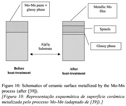
The Moly-Mn process has been widely used for many years and is reported to be one of the first metallization techniques applied to join metals to ceramics, mainly Al2O3. The approach consists in sintering metallic powders on ceramic surfaces. Due to its elevated sintering temperature, Al2O3 is metallized with refractory metals. Molybdenum and tungsten are often used because of their low coefficient of thermal expansion [12, 79]. Different metallizing pastes containing Mo and Mn powders can be dissolved in a solvent and used (Table V). A glassy phase is added to the paste for joining highly pure ceramics with less than 3% amorphous grain boundary phases, especially SiC and some types of Si3N4 [12, 39, 79].
A schematically diagram of the process is shown in Fig. 10. A thin layer of a metallizing paste is applied onto a ceramic surface which is subsequently heated to 1300 ºC - 1600ºC in a moist nitrogen-hydrogen (75%N2 25%H2) atmosphere. Under these conditions, the vitreous phase present in the bulk of the ceramic substrate moves to its surface by capillary forces and react with Mn at around 1400ºC forming spinels, such as MnAl2O4 (when joining Al2O3). Simultaneously, Mo particles are sintered onto the spinel layer, whose main function is to link the ceramic substrate to the metallic film formed [39, 69, 80]. Although the method requires an additional high-temperature step, ceramics previously metallized by the Mo-Mn process are commercially available. Metallized ceramics cost approximately 30% more [39].
An alternative metallization route is the TiH2 process. A coating layer of TiH2 powder dissolved in nitrocellulose is manually applied to the ceramic surface. Upon heating to the brazing temperature, the hydride dissociates around 450 ºC and a direct contact between the ceramic surface and Ti is established. Brazing is accomplished using conventional filler alloys with no active metal [81].
Si3N4 has been metallized using Ti salts. A mixture of NaCl and KCl containing 5 to 10 wt.% of a Ti-F-K compound is prepared and placed in a furnace at 700 e 1100 ºC under argon. Si3N4 parts are then immersed in the molten mixture several times until reaction occurs between the ceramic and the salts producing a metallic layer. Next, the ceramic is cleaned, dried and brazed [71, 73]. Drawbacks associated with the method include: i) the ceramic is entirely metallized which alters the properties of surfaces which are not brazed, ii) the process is long and requires a specific furnace for melting salts and iii) the method is not environmentally safe as the chemicals used and the residues are toxic.
Another commercial metallization method was developed by Sameer (Society for Applied Microwave Electronics Engineering and Research of India). The solution metallization method consists in applying a water-soluble ink containing ~ 90 % ammonium molybdenate and 10 % potassium permanganate to alumina substrates and placing them at 1050ºC under moist hydrogen. Although simple, the process requires successive inking and heating to form metallic films that allow for brazing. The method is time and energy consuming [72].
Finally, the mechanical metallization is a new, simple and fast method to metallize ceramics. It was developed and patented by the Jülich Research Center, in German (Forschungszentrum Jülich). The process has been initially studied for the metallization of alumina and zirconia with Ti [82-84].
Mechanical Metallization
Planar ceramic surfaces can be mechanically metallized by frictioning a metal against them. Preliminary experiments have been carried out using either cone-shaped or (and) planar tools made of titanium. Al2O3 and non-oxide ceramics SiC and Si3N4 - have been mechanically metallized with Ti and subsequently brazed to low-expansion alloys and stainless steel. Conventional tool machines can be used just adapting a device to generate and control the relative movement between metal and ceramic (Fig. 11) [82]. The process is based on the wear and deposition of a metal as it is frictioned against a harder ceramic surface.
Numerous advantages are associated with this process [82]:
a) Conventional tools can be used;
b) Metallization occurs at room temperature;
c) No chemicals are used and no hazardous residues are formed. The process is environmentally safe;
d) Large choice of coating metals or alloys;
e) Selection of coating area;
f) Easy automation of the process and adaptation for non-planar surfaces and
g) Applicable to batch and large scale production
Mechanical metallization with Ti and subsequent brazing of alumina substrates has been investigated. Conventional active metal free filler alloys have been used. Ti reacts with alumina and molten Ag/Cu and Au/Ni alloys at the brazing temperature resulting in a thin reaction layer (equation I) responsible for the microstructural connection between filler alloy and ceramic substrate. As a reaction layer is formed, Ti also dissolves in the molten filler alloy forming other interfacial phases [8, 85].

Studies on mechanical metallization of alumina with Ti have shown that the quality of the metallic film deposited onto the ceramic is strongly affected by process parameters. These can be adjusted within wide ranges in order to optimize the quality of the films. The films are characterized by a distribution of voids. According to the number and size of these voids, microstructural defects can be formed. Fig. 12 shows the film and distribution of defect size of a Ti-film mechanically deposited onto alumina. Roughly 80% of the defects are between 0.010 mm and 0.023 mm in diameter and ~ 95% of all defects are smaller than 0.05 mm in diameter [8, 85].
The mechanical metallization process is experimentally simple and straightforward but its rationalization is rather complex. It involves equations from the classical mechanical to model the dynamic friction between contact surfaces; surface wear also has to be considered and requires knowledge on the elastic and plastic properties of the tribological couple and their dependence with temperature. Thermal phenomena are also important since heat generation, dissipation and flow towards the metallic and ceramic components affect the film deposition [8].
Finally, the ceramic counterpart should be carefully characterized. Disadvantageous combinations of metallization parameters and surface roughness can lead to brittle fracture and chipping as a result of the relatively high force applied to the metallization tool against the ceramic surface as well as the vibration and corresponding impact of the metallization system [8].
Adhesion of the Ti film onto the ceramic takes place by particle interlocking and physical bonding. Metallization occurs at room temperature, which is insufficient to dissociate the ceramic with contact with Ti and to form interfacial compounds [8].
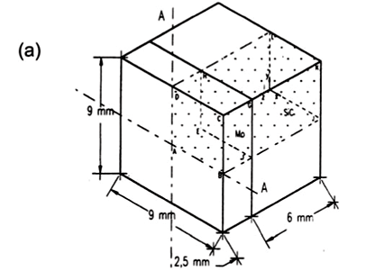
The thickness of typical Ti films mechanically applied onto ceramic substrates is of the same order of magnitude of Rz, i.e., the roughness parameter for the ceramic. Films deposited onto alumina were about 5 ± 2 mm thick (Fig. 13).
BRAZING
Brazing has been extensively investigated and employed for metal/ceramic joining. The process does not require costly equipment and can be easily automated. Strong and heat-resistant joints are commonly produced in large number [4, 41, 86, 87]. Great efforts have been focused on improving reliability and reproducibility of the process. Superior quality directly depends on the adherence of the filler alloys to the surfaces of the base materials and the ductility of eventual interfacial reaction compounds [35, 36, 38, 43]. New routes have been developed mainly to improve wetting of the filler alloys to ceramic substrates [88, 89]. For instance, oxide ceramics such as Al2O3 and SiO2 can be superficially treated with high power laser beams. A thin layer of ceramic material (50 mm 100 mm) is melted. This significantly reduces the contact angle with the filler alloy [8, 90, 91]. Pre-oxidation of SiC has also been carried out in an attempt to improve wetting with commercial Ti-based filler alloys, such as (Cusil, Cusil ABA, and Incusil). Reactions involving Ti and the ceramic surfaces, SiC and SiO2, an their effect on the contact angle have been studied [49].
Ceramic/metal and ceramic/metal brazing were originally carried out following metallization of the ceramic surface(s) using the conventional Moly-Mn method. This can be attributed to the domain of the metallization technique and the price and difficulty associated with obtaining active filler alloys. Direct brazing using active filler alloys is a single step process that does not require furnaces capable of operating between 1300 and 1500 ºC, necessary for metallization with Moly-Mn. This is a very attractive feature when considering production at commercial scale. The development of active alloys containing Ti played a very important role in expanding the use of direct brazing [53, 92]. Significant research was directed towards optimizing technological parameters and describing the metallurgical reactions that took place during the process as the basis to determine interfacial microstructure.
Different active elements can be used in filler alloys: Nb, Ti, Ta, Zr, Hf. By far, Ti is the most common one. They chemically react with the ceramic surface, promoting dissociation and formation of a reaction zone [5, 44, 53]. Because of the high affinity of these elements for oxygen, brittle oxide layers, such as TiO2 and NbO2, easily form in the ceramic/filler alloy interface. Although useful for establishing a chemical bridge between the base materials, excessive brittleness is deleterious to the mechanical strength of the joint, as it reduces the ability of the couple to absorb residual thermomechanical stresses. Optimizing parameters means that the contents of the active element should allow for a balance between maximizing wetting and minimizing the contents of interfacial oxides.
Another growing research area in ceramic brazing concerns the development of active filler alloys but no noble metals (Ag, Au). Alloys such as CuNiTiB, CuGaTi, and In-Ti have been used to braze nitride ceramics [22, 25, 93]. Ti has also been replace by Zr in Al2O3/alloy steels brazing [94]. High-temperature joints have also been brazed using high-melting point Au-Ni-Mo filler alloys containing V as active element. Ni-Cr-Si alloys have been used to braze Si3N4 [23, 24, 95]. As a general goal, the reactions between a number of structural ceramics and filler alloys in both direct and indirect brazing have been studied. The thermodynamics of interface formation between ceramics and different filler alloys has also been object of studies. [9, 21, 27, 95-97].
The formation of a reaction zone between a ceramic and a filler alloy depends on the activation of chemical reactions [11]. The reactions that form an interface take place only when the formation of a new phase reduces the Gibbs free energy of the system. For their nature, they should be described by the thermodynamics of irreversible processes where their entropy is determined by the chemical potential, mass, and heat flow of the reacting species [11]. As such data is not readily available for the vast majority of ceramic/metal combinations, equilibrium thermodynamics is often applied as first approximation. The behavior of a system is described by the variation in the Gibbs free energy, DG, of the reactions which are likely to occur [5, 11].
Al2O3 has been joined to metals using filler alloys containing Ti. Alumina is more stable than titanium oxides. The reduction of alumina to form a reaction layer is thermodynamically possible because it is limited to the surface. Reduction of surface material requires less energy than for bulk material, i.e, DGAl2O3Sup. >DGAl2O3o [53]. Reaction between dissociated surface atoms from the ceramic and the molten filler alloy is represented by

where M represents the active metal of the filler alloy [53, 98], and grants the necessary ceramic wetting to promote joining.
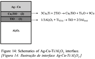
Ti from Cu-Ag based active alloys reacts superficially with alumina forming a thin layer of oxides, whose stoichiometry, TiO, Ti2O3, Ti3O5, Ti4O7 or TiO2, depends on the activity of Ti in the filler alloy [15, 98-100]. A second layer of reaction products can be formed on top of the primary oxide zone and is originated from the reaction of Ti with Cu from the filler alloy, resulting in mixed Cu-Ti oxides [46, 101]. Fig. 14 represents a general aspect of an interface between alumina and Ag-Cu-Ti. A good agreement could be established between experimental results and the proposed distribution of reaction products from equilibrium thermodynamic equations for that particular system.
In the chemical equations written in Fig. 14, Al from the reduction of alumina and Ti which is originated from the filler alloy and is responsible for such reduction depict are both dissolved in Cu. This is symbolized by Al(Cu) and Ti(Cu) [46, 101]. At the brazing temperature, Ti segregates and moves towards the surface promoting the dissociation of alumina into aluminum and oxygen. The latter react with Ti according to equation (J) forming the primary oxide layer, which rapidly coats the entire surface of the ceramic [46]. In the formation of the mixed Cu-Ti oxide, Al(Cu) is now dissolved by Cu-Ti-O [46, 101]. It should also be mentioned that oxygen from the filler alloy and the brazing atmosphere can also oxidize Ti, since the partial pressure of oxygen in the brazing atmosphere (at about 1.0 x 10 -6 mbar) is far greater than that necessary to prevent the oxidation of Ti, i.e., 1.0 x 10 -19 mbar [44].
Ti-oxides from layer 1 are almost as stable as alumina, which prevents wetting of the Ag-Cu alloy. Reaction layer 2 is formed by a mixed oxide, which wets the Ti-oxide (layer 1) and promotes the formation of a transition structure responsible for the structural link between ceramic and filler alloy [101]. Since Ti moves towards the surface of the ceramic, it should be expected a reduction in the Ti contents at the remainder of the interface microstructure (filler alloy) at the brazing temperature.
Ticusil is a commercial filler alloy with 4.5 wt.% Ti and is extensively used to braze alumina. The microstructure of brazed Al2O3/Fe-28Ni-18Co interfaces using Ticusil has been characterized as a function of the brazing time [102]. The presence of a Ti-rich reaction layer and intermetallic phases could be established. The formation and distribution of interfacial reaction products from have been extensively investigated to assist in the interpretation of the mechanisms involved in interface growth. Both thermodynamic and kinetic aspects have been taken into account [1, 46, 99, 101]. Incusil ABA (Ag-Cu-Ti-In) is also widely used as filler alloy in metal/ceramic joining. It has been shown that both the thickness of the reaction layer and its Ti contents are affected by the brazing cycle. The microstructure of a brazed joint using Incusil is shown in Fig. 15, revealing the existence of a reaction layer in contact with alumina.
Indirect brazing of ceramics to metals can be accomplished using conventional (non-active) and inexpensive filler alloys on metallized ceramics. Other metallization techniques have been simultaneously developed as an alternative to the Moly-Mn process and the use of active filler alloys [75, 82] in an attempt to reduce costs. It is evident, however, that novel approaches for brazing in large scale should not require expensive machinery, numerous steps or high temperature furnaces [79, 82]. Mechanical metallization is an interesting solution in this case. Alumina and non-oxide ceramics have been mechanically metallized with Ti and subsequently brazed to Cu or low expansion alloys (kovar and vacon 70) using conventional filler alloys without active metal [8].
In joints brazed after mechanical metallization of the ceramic, the interaction between filler alloy, Ti-film and ceramic substrate resulted in the precipitation of a reaction layer and Ti-containing intermetallic phases. It is in the precipitation zone that the filler alloy reacts with Ti (Fig. 16) whereas the reaction layer results from the reaction between the ceramic substrate and Ti. The microstructure of brazed joints after mechanical metallization shows a well-defined precipitation zone, generally more accentuated than that observed in brazed joints with active filler alloys. On the other hand, reaction layers on metallized surfaces are normally discontinuous. The reactions between active filler alloy and ceramic substrate usually take place above 850 ºC [1]. However, with the mechanical metallization the intermetallic precipitation and reaction products were formed at 820 ºC [85].
Reaction layers on metallized brazed joints were usually between 2 and 4 mm thick as a result of the wavy and discontinuous aspect of the deposited Ti-films. In defect areas, wetting took place because the filler alloy becomes active, however, the local availability of Ti is lower at these points thus reducing the thickness of the reaction layer. At the brazing temperature, Ti from the metallic film is in the solid state and forms an interface with the liquid filler alloy (Fig. 17). As the process takes place, Ti from that interface is dissolved by the filler alloy forming an active filler, which extends itself to about 25 mm from the ceramic surface. The increase in Ti contents in the filler alloy ultimately results in the formation of the precipitation zone.
MECHANICAL BEHAVIOR
Ideally, the mechanical strength of a ceramic/metal joint component should be higher than those of its constituents. The joint should fail at one of the base materials. In reality, joints fail at lower strengths, either because of the interfacial strength is inherently lower or because of residual stresses which lower the strength of the ceramic counterpart. Effective joining should grant strength levels compatible to the demand of the intend application along with maximum reliability [103]. Joint strength is mainly determined by
Joining process and related parameters. The strength of brazed joints, in particular, depend on the quality of the metallized layer (when present), filler alloy, and brazing cycle;
Intrinsic properties (Young modulus and coefficient of thermal expansion) and characteristics (roughness and toughness of the ceramic) of the base materials, especially the ceramic for its brittle nature and
Joint type (planar or fitted) and geometry (cylindrical or rectangular).
However, a fundamental aspect on ceramic/metal mechanical strength is the composition and microstructure of the interface. The presence of intermetallics (usually brittle) along with the thickness and morphology of reaction layers can drastically enhance or dwindle the strength of the joint. The presence of organic material or impurity particles either on the surfaces to be joined of in the filler alloy (for brazing) is deleterious to the interfacial microstructure. Joining defects are created. These areas of joining discontinuities increase local stresses and promote crack nucleation and growth (Fig. 18) [5, 11, 102, 103]. In particular, ceramics are quite susceptible to the presence of microcracks and areas of high local stresses. Upon cooling, the ceramic is often submitted to tensile stresses capable of growing existent cracks and nucleating new ones.
In addition, controlling the thickness of interfacial oxide layers calls for additional caution. Usually brittle, reaction oxide layers can be the limiting aspect on the mechanical strength of otherwise sound joints and should be characterized by statistical analyses and represented by Weibull plots [5, 11, 12, 104]. As for ceramics, joint strength should be characterized by statistical analyses. Tensile, flexural (3- or 4-point bending) and shear tests are commonly used [5, 11, 12]. Fig. 19 illustrates the sample geometry and test configuration used in the mechanical characterization of ceramic/metal joints. According to Weibull's weak link theory, tensile tests are the most appropriate approach [104]. The volume under tension is maximum and the result is representative of the whole test specimen. However, close tolerances and expensive machining due to the large number of samples required are limiting aspects. Results are characterized by large scattering.
Although specimens for bending tests also require adequate finishing to assure planar and parallel surfaces, tight tolerances are more paramount and the alignment between sample and test machine is easier to accomplish. Scattering is also reduced and therefore, the results are more reliable. Higher values are measured compared to tensile tests since the volume under tension is smaller [104, 105]. Comparing the volume under tension, V, and the strength resulting from tensile and 3- and 4-point bending tests yield

Weibull's statistical method should make it possible to transfer results from one test to another taking into account the differences in volume under tension. Although applied to monolithic ceramics with reasonable success the approach has not yielded satisfactory results for joint strength [12,104]. Transfer rates from tensile tests to 3-point bending of x 1.7 were calculated for Si3N4 - Al - Invar joints. Experimental values were about 2.5. Major sources of errors can be attributed to differences between the calculated and real stress distributions, presence of residual stresses, and plastic deformation upon test loading [5, 12].
Residual stresses result from mismatches in the coefficient of thermal expansion and elastic modulus of the base materials. Upon cooling from the relatively high joining temperatures, characteristic of usual joining processes, the interface restricts the contraction of the material, concentrating local stresses [5, 11]. The magnitude and distribution of residual stresses in and around ceramic/metal interfaces depends on a number of aspects, such as joint geometry, joining temperature, thickness and composition of reaction layers, in addition to intrinsic mechanical properties of the base materials [4, 5, 14].
Thermal stresses affect the results from mechanical tests and increase their scattering [4, 5]. For cylindrical samples, the magnitude of thermal stresses increases with the diameter of the sample and reach its maximum near the border. The sharp edges of rectangular specimens also concentrate stresses [4,5]. Minimizing residual stresses significantly contributes to increasing both the mechanical strength and reliability of joint components. Different approaches related to design and process can be used to reduce stresses.
Joint geometry can be optimized to avoid areas of stresses concentration and maximize strength. Measures should also be taken towards minimizing property mismatches. Ductile metal layers (e.g. copper or aluminum) can be inserted at the interface to accommodate stresses [5,12] whereas refractory metals and expansion-controlled alloys (Invar, Kovar and Superinvar) can be used to promote a gradual transition from the ceramic to the metal, thus reducing CTE mismatches [4, 5, 12].
The evaluation of thermal residual stresses can be performed either experimentally (X-ray or neutron diffraction) or numerically using the Finite Element Method (FEM) [5]. X-ray diffraction is far more employed than neutron diffraction due to experimental availability. A disadvantage associated with the method consists in the limited penetration of the radiation into the material. Stress analysis is limited to shallow depths and bulk stresses cannot be assessed. Neutron diffraction, on the other hand, provides full penetration but requires longer data collecting periods and a neutron source [5].
The numerical approach, FEM, has been widely used to evaluate residual stresses [11, 106, 107, 108]. Simpler, faster, and much cheaper than the experimental techniques, complete 2- or 3-dimensional stress maps can be obtained. The key to successful numerical analyses relies on the selection of materials property, the proposed mechanisms for interface formation, and the development of elastic or elastic-plastic deformation models [5]. Modeling of complex and thick reaction layers (~ 3 mm) can be extremely complicated and normally induce erroneous responses.
The basis for the diffraction techniques is the peak shift that accompanies lattice distortion due to the presence of residual stresses. Neutron diffraction experiments depend on the availability of a neutron source, however the results provide valuable information on the distribution of stresses not only near the edges but also in the bulk of joined components. Neutron diffraction analyses rely on establishing differences between the angular position of specific peaks comparing stress-free reference sample and joined components. A polychromatic neutron beam in generated at the source and collimated toward a monochromator crystal. The monochromatic hits a sample normally placed on top of a moving table. The spatial position of the sample is adjusted by a set of independent stages. The x- and y-coordinates are usually variable and the z-coordinate fixed (Fig. 20). The beam height can be set to be greater than the sample height in order to integrate the diffraction process through the entire sample, i.e., along the y-axis. The diffraction angle is given by

where q is the Bragg angle. Values of f should be chosen in order to maximize the intensity of the diffracted peak and minimize distortion of the sampling volume (f » 90º). It should be noted that the intensity of a neutron beam is far less than the intensity of an X ray beam. Strains can be defined as [109]

where d corresponds to the spacing between a particular set of crystallographic planes under tension or compression. If the sample is under tension, the planes are pulled slightly apart so that d increases with respect to a strain-free value, do. Conversely, if the sample is under compression, the planes are pushed together and d decreases with respect to do. The angle of rotation of the table (y) is adjusted to select the geometry of the diffraction process and, therefore, the strain component under investigation. The normal component of strain (ez) is studied by setting y equal to f/2, and the in-plane component (ex) by setting equal y equal to f/2 + 90º. The stresses are then calculated according to

where E is the elastic modulus, and v is the Poisson's ratio. A cyclic permutation of indices yields the other two components of stress (sy and sz). Although for symmetric samples, it is usually assumed that strains along both in-plane components are equivalent (ex = ey), this is somehow an oversimplification. From a mechanical standpoint, the only area that satisfies this assumption is situated on the middle edge z of the sample, and rigorously, ex is different from ey almost everywhere. On the other hand, ex is a result of an integrated measurement along the entire height of the sample. Thus, when measurements were performed along the z-axis, ex may be recognized as a representative value of the middle point of the transversal section and, hence, the hypothesis is applicable.
Results obtained from hot-pressed SiC-Mo joints with rectangular cross section are shown in Fig. 21 [109].

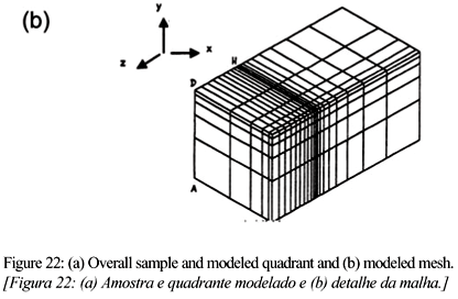
The distribution of residual stresses in SiC-Mo joints was studied along a line perpendicular to the SiC/Mo interfaces (Fig. 21a). Maximum sx stress (330 MPa) was measured on the molybdenum side of the joint at a distance of 0.25 mm from the interface (Fig. 21b). On the SiC side, a corresponding value of -150 MPa was measured at an equivalent distance from the interface. SiC was in compression in the direction of sx, whereas molybdenum was in tension. Evidently, this occurrence was a result of the CTE mismatch between the materials. Molybdenum has a higher CTE than SiC; therefore, it contracted more during cooling of the joint from the joining temperature. However, its contraction was restrained by its bonding to SiC, thus resulting in compressive stresses on the ceramic side. Molybdenum reacted to that tendency, trying to extend the interface, yielding the concentration of tensile stresses, especially near the interface with SiC. On both the ceramic and metal sides, the amplitude of sx decreased as the distance from the interface increased. On the SiC side, sx was almost zero at a distance of 1.5 mm, whereas on the molybdenum side, residual stresses were measured at an equivalent distance, as a result of the plastic deformation of the metal. In contrast, sz remained nearly null (within the margin of error) for most of the region analyzed, with an oscillating pattern that resulted in slight tension on the metal side and compression on the ceramic side. This behavior was confirmed by FEM analysis. To that end, a tridimensional thermal elastoplastic model was generated to study those joints. A preliminary analysis was performed considering both materials as ideally linear-elastic components. Subsequently, a model where only the ceramic was considered to be linear-elastic throughout the thermal loading was constructed. In this case, the metallic component was modeled considering an elastic-perfect-plastic behavior, the von Mises yield criterion, and the associative Prandtl-Reuss flow rule. The program used allowed the constitutive behavior to be modeled using kinematic hardening, as very low values of the tangent modulus were involved, i.e., ET/E = 0.05. Because of the typically high joining temperatures, the variation of the mechanical properties of the material with temperature must be considered, especially Young moduli, linear coefficients of thermal expansion, as well as yield strength and tangential modulus of the metal. Poisson's ratio could be assumed to be constant. The symmetry of the joined couple with respect to geometry, mechanical properties, and loading may allow significant simplification of the model. Only one quadrant of rectangular joints, such as that illustrated in Fig. 22 [109], can be modeled. A sequence of finite-element mashes was then built. Firstly, a uniform mesh composed of trilinear hexagonal elements was considered. Subsequently, to improve the accuracy of the analysis near the interface (region of stress concentration), a triquadratic mesh was considered (Fig 22b). In addition, sample cooling was assumed to occur free from mechanical loads. The temperature distribution inside the diffusion couple was assumed to be uniform, to avoid the need to solve a heat-transfer equation during the iterative process. This assumption is quite straightforward considering that cooling times are usually long enough considering the thermal diffusivity of metals and the relatively limited size of the joints. Creep effects were not considered.
A comparison of numerical and experimental results (Fig. 23) showed a reasonable agreement between experimental and calculated values for the sx stress component of SiC-Mo joints, especially on the ceramic side of the joint. Further refinement of the numerical model must include creep effects and viscoplastic relief of the metal.
FEM analyses may also provide a complete map of all stress components, including shear stresses, which are particularly hard to obtain experimentally. An example of normal and shear stress maps obtained from Fe-Ni-Co/Al2O3 brazed joints is shown in Fig. 24 [110].
CLOSING REMARKS
Ceramic-metal joining processes and their resulting interfaces have been extensively studied over the years. New developments in the field have granted structural ceramics new horizons in applications involving adverse conditions and reliable materials. Brazing has been widely employed to join ceramics to metals as a direct consequence of interesting characteristics such as low-cost and easy operation, reproducibility and large-scale production. The resulting interfaces generally depict superior tightness and adequate mechanical strength. On the other hand limited wetting and the development of thermal residual stresses have pushed forward studies on the improvement of the method. Wetting determines the nature of the bonding forces and microstructure of the interface whereas the distribution and amplitude of residual stresses determine reliability. Early industrial applications for metal-ceramic joints heavily depended on the metallization of the ceramic counterpart, mainly using the Moly-Mn process. Further developments aimed at adding active metals to conventional filler alloys in an attempt to eliminate the metallization stage. Brazing parameters were optimized for a number of such alloys and base materials. Nevertheless, the cost of active filler alloys hindered many potential applications. New, improved and versatile wetting methods including mechanical and plasma metallization have then been investigated resulting in significant cost reduction for a wide range of applications. Concurrently, residual stresses have been minimized by adjusts on joint geometry and composition of base materials, including the use of low-expansion alloys. Experimental results on joint stress distributions in addition to modeling programs have greatly assisted in improving design and material selection.
Rec. 12/09/03, Ac.07/11/03
- [1] W. Tillmann, E. Lugscheider, R. Xu, J. E. Indacochea, J. Mater. Sci. 31 (1996) 445.
- [2] H. Ohnabe, S. Masaki, M. Onozura, K. Miyahara, T. Sasa, Composites Part A: Appl. Sci. & Manuf. 30 (1999) 489.
- [3] J. A. Chediak, Am. Ceram. Soc. Bull. 75, 1 (1996) 52.
- [4] K. Suganuma, ISIJ Int. 30, 12 (1990) 1046.
- [5] A. E. Martinelli, "Diffusion bonding of silicon carbide and silicon nitride to molybdenum". PhD Thesis, McGill University, Montreal, Canada (1996).
- [6] M. G. Nicholas, Advanced Joining Technologies, Proc. Int. Inst. Welding Congress on Joining Research (1990) 161.
- [7] R. D. Watkins, ASM Handbook, Ceramics and Glasses, Vol. 4 (1991) 478.
- [8] R. M. Nascimento, " Metalização Mecânica de Al2O3 para Brasagem Metal/Cerâmica", D. Eng. Thesis, UFSC, Brasil (2001) in Portuguese
- [9] O. C. Paiva, M. A. Barbosa, J. Mater. Sci. 35 (2000) 1165.
- [10] K. Suganuma, Mater. Res. Soc. Symp. Proc. 314 (1993) 51.
- [11] J. A. Howe, Intern. Mater. Rev. 38, 5 (1993) 257.
- [12] J. T. Klomp, G. De With, Mater. & Manuf. Proc. 8, 2 (1993) 129.
- [13] M. M. Schwartz, Ceramic Joining, ASM International, 1990.
- [14] G. Elssner, G. Petzow, ISIJ Int. 30, 12 (1990) 1011.
- [15] O. M. Akselsen, J. Mater. Sci. 27 (1992) 1989.
- [16] M. Boretius, E. Lugscheider, W. Tillmann, "Fügen von Hochleistungskeramik: Verfahren-Auslegung-Prüfung-Anwendung". VDI- Verlag GmbH, Düsseldorf (1995) in German
- [17] L. Shepeleva, B. Medres, W. D. Kaplan, M. Bamberger, M.H. McCay, T. D. McCay, M. Sharp. Surf. & Coating Tech. 125 (2000) 40.
- [18] V. Curicuta, D. E. Poulain, D. R. Alexander, R. J. de Angelis, S. Gasser, E. Kolawa, Mater. Sci. Eng. B 68 (2000) 186.
- [19] K. Suganuma, Mater. Res. Soc. Symp. Proc. 314 (1993) 51.
- [20] V. Curicuta, D. E. Poulain, D. R. Alexander, R. J. de Angelis, S. Gasser, E. Kolawa, Mater. Sci. Eng. B 68 (2000) 196.
- [21] T. H. Chuang, M. S. Yeh, Y. H. Chai, Metallurgical and Materials Transactions A. 31A (2000) 1591.
- [22] D. Huh, D. H. Kim, J. Mater. Res. 12, 4 (1997) 1048-1055.
- [23] M. R. Rijnders, S. D. Peteves, Scripta Mater. 41, 10 (1999) 1137.
- [24] A. M. Hadian, R. A. L. Drew, J. Eur. Ceram. Soc. 19, 8 (1999) 1623.
- [25] H. Xiong, C. Wan, Z. Zhou, Metallurgical and Materials Transaction A 29A (1998) 2591.
- [26] S. D. Peteves, M. Paulosto, G. Ceccone, V. Stamos, Acta Mater. 46, 7 (1998) 2407.
- [27] M. Paulasto, J. Kivilahti, J. Mater. Res. 13, 2 (1998) 343.
- [28] J. Besson, J. L. Terrier, PH. Dubois, Metal. Trans. A 23 (1992) 2791.
- [29] T. Itoh, H. Kimura, J. Eng. Gas Turbines and Power 115 (1993) 42.
- [30] K. Takama, S. Sasaki, S. Shimizu, N. Kamiya, J. Eng. Gas Turbines and Power 115 (1993) 17.
- [31] Y. Katano, M. Ando, T. Itoh, M. Sasaki, J. Eng. Gas Turbines and Power 115 (1993) 9.
- [32] H. Kawase, K. Kato, T. Matsuhisa, T. Mizuno, J. Eng. Gas Turbines and Power 115 (1993) 23.
- [33] B. Wielage, D. Ashoff. Aktivloeten von Ingenieurkeramik. Hart- und Hochtemperaturlöten: Vorträge des gleichnamigen 9. Dortmunder Hochschulkolloquiums. DVS Berichte band. 132 (1990) 15 in German
- [34] A. Guedes, A. M. P. Pinto, M. Vieira, F. Viana, Mater. Sci. Eng. A 301 (2001) 118.
- [35] American Welding Society, Welding Handbook, 7th Ed., Vol. 2 (1978).
- [36] British Standards Institution, Guide to Brazing, Part 2: Brazing, BS 1723 (1986).
- [37] K. Nogi, K. Oisshi, K. Ogino, Materials Transactions 30, 2 (1989) 137.
- [38] DIN 8505 Standard T1 Löten; Allgemeines, Begriffe (Mai 1979) und DIN 8505 T2 "Löten; Einteilung der Verfahren", Begriffe (1979) in German
- [39] R. Lison, Wege zum Stoffschluß über Schweiß- und Lötprozesse. Fachbuchreihe Schweißtechnik, Band 131. Verlag für Schweißen und verwandte Verfahren DVS - Verlag GmbH, Düsseldorf (1998) in German
- [40] L. Dorn, P. Dorner, K. Iversen, J. Kinzel, H. Pelster, E. Lugscheider, H. Schchinger, Hartlöten: Grundlagen und Anwendungen. Expert Verlag, Sindelfingen (1985) in German
- [41] J. A. Hamill Jr, Int. J. Powder Metal. 27, 4 (1991) 363.
- [42] R. Arróyave, T. W. Eagar, Acta Mater. 51 (2003) 4871.
- [43] M. M. Schwartz, Brazing, ASM Int. (1995).
- [44] E. Lugscheider, W. Tillmann, Mater. & Manuf. Proc. 8, 2 (1993) 219.
- [45] M. G. Nicholas, T. M. Valentine, M. J. Waite, J. Mater. Sci. 15 (1980) 2197.
- [46] P. R. Chidambaram, G. R., Edwards, D. L Olson, Metal. & Mater. Trans. A 25 (1994) 2083.
- [47] WESGO, Inc. Brazing Alloy, Active metal alloys catalogue, CA (1994).
- [48] Degussa AG, Loettechnik und Durferrit-Verfahren, Catalogue (2001).
- [49] J. Lopez-Cuevas, H. Jones H. V. Atkinson, Mater. Sci. Eng. A 266 (1999) 161.
- [50] D. Huh, D.-H Kim, J. Mater. Res. 12, 4 (1997) 1048.
- [51] R. K. Shiue, S. K. Wu, J. M. O., J. Y. Wang, Metal. & Mater. Trans. A 31 (2000) 2527.
- [52] D. J. Cawley, Introduction to Ceramic-metal Joining, Metal-Ceramic Joining, Eds.: P. Kumar, V. A. Greenhut - The Minerals, Metals & Materials Society (1991) p. 3.
- [53] P. R. Chidambaram, G. R. Edwards, D. L Olson, Metallurgical Transactions B 23 (1992) 215.
- [54] A. M. Hadian, "Joining of silicon nitride-to-silicon nitride and to molybdenum for high-temperature applications", Ph.D. Thesis, McGill University, Montreal, Canada (1993).
- [55] J. A. Pask, A. P. Tomsia, Surfaces and Interfaces in Ceramic and Ceramic-Metal Systems, Mater. Sci. Res. 14 (1986) 411.
- [56] K. M. Martorano, "Molhamento e espalhamento de estanho e da liga 60%Sn-40%Pb sobre chapas de cobre e ligas cobre-estanho", D.Eng. Thesis, EPUSP (2001) in Portuguese
- [57] A. J. Moorhead, H. Keating, Welding J. 65 (1986) 17.
- [58] M. D. Baldwin, P. R. Chidambaram, G. R., Edwards, Metal. Trans. A 25 (1994) 2497.
- [59] E. Saiz, R. M. Cannon, A. P. Tomsia, Acta Mater. 48 (2000) 4449.
- [60] S. D. Brandi, "Molhamento e espalhamento de ligas Ag-Cu-Ti, Ag-Cu-Ti-In e Ag-Cu-Nb sobre nitreto de silício", Tese de livre docência, EPUSP, S. Paulo (1995) in Portuguese
- [61] A. Meier, P. R. Chidambaram, G. R. Edwards, Acta Mater. 46, 12 (1998) 4453.
- [62] J. A. Pask, A. P. Tomsia, L. Berkeley, ASM Handbook Ceramics and Glasses, Vol. 4 (1991) 482.
- [63] J. Zhu, A. Kamiya, T. Yamada, W. Shi, K. Naganuma, K. Mukai. Mater. Sci. Eng. A 327 (2002) 117.
- [64] N. Eustathopoulos, Acta Mater. 46, 7 (1998) 2319.
- [65] H. H. Van Der Sluis, Active brazing of technical ceramics, in: High Temperature Brazing and Diffusion Welding, Proceedings, Germany (1992) pp. 68-72.
- [66] M. Voué, J. De Coninck, Acta Mater. 48 (2000) 4405.
- [67] A.G. Evans, B. J. Dalgleish, Mater. Sci. Eng. A 162, 1-29 (1993) 1-13.
- [68] J. A. Howe, Int. Mater. Rev. 38, 5 (1993) 233.
- [69] A. A. Prokopenko, V. S. Zhuravlev, Y.V. Naidich, J. Mater. Sci. Lett. 17 (1998) 2121.
- [70] F. G. Yost, Scripta Mater. 42 (2000) 801.
- [71] J. Chen, P. Wei, J. Lian, L-H. Du, Y. Huang, J. Mater. Sci. Lett. 17 (1998) 2113.
- [72] S. Das, A. N. Tiwari, A. R. Kulkarni, T. S. Syunry, Am. Ceram. Soc. Bull. 78, 2 (1999) 85.
- [73] P. Wei, J. Chen, Y. Huang, J. Mater. Sci. 35 (2000) 3685.
- [74] A. Doi, H. Kawai, T. Yoshioka, S. Yamanaka, Vapor deposition ceramic coating: Status and Prospect, Conf. High Performance Ceramic Films and Coating, Elsevier Science Publishers, Ed.: P. Vincenzini (1991) p. 77.
- [75] L. C. Fontana, "Estudo da deposição de filmes de Ti e TiN e desenvolvimento do sistema modificado triodo-magnetron-sputtering", D. Eng. Thesis, Mechanical Engineering/UFSC (1997) in Portuguese
- [76] B. Wielage, K. Mohwald, D. Ashoff, Löten von PVD-metallisierter Ingenieurkeramik. Hart- und Hochtemperaturlöten: Vorträge des gleichnamigen 9, Dortmunder Hochschul-kolloquiums. DVS - Berichte band 132 (1990) pp. 25-29 in German
- [77] B. Chapman, Glow Discharge Processes - Sputtering and plasma etching, Wiley-Interscience Publ., USA (1980).
- [78] L. C. Fontana, J. L. R. Muzart, Surf. Coat. Tech. 107 (1998) 24.
- [79] H. Mizuhara, T. Oyama, Ceramic/Metal seals, ASM Handbook, Ceramics and Glasses, Vol. 4 (1993) 502.
- [80] S. H. Yang, S. Kang, J. Mater. Res. 15, 10 (2000) 2238.
- [81] J. R. Martinelli, A. C. Bastos, P. R. Jr. Pascholati, J. E Takahashi, A.Wulfhorst, Anais do 39ş Congresso Brasileiro de Cerâmica, Águas de Lindóia, SP (1995) p. 991 in Portuguese
- [82] R. Lison, Verfahren zum verlöten zweier keramiken oder einer keramik mit einen metall. Patent P.T, 1.1481, Germany.
- [83] P. Wille, Untersuchung des Lötverhaltens von Ti-beschichteten Oxidkeramiken bei der Herstellung von Metall-Keramik-Verbindungen, Diplomarbeit, Fachhochschule Aachen (1999) in German
- [84] R. Classen, K. Watermeyer, Prakt. Metallogr. 38, 1 (2001) 38.
- [85] R. M. Nascimento, A. J. A. Buschinelli, A. E. Martinelli, E. Sigismund, J. Remmel, U. Reisgen, E. Lugscheider, 6th Int. Conf. on Joining Ceramics, Glass and Metal, Munich, Germany (2002) p. 58.
- [86] F. Moret, N. Eustathopoulos, J. Phys. IV 3 (1993) 1043.
- [87] R. M. Nascimento, A. J. A., Buschinelli, E. Sigismund, J. Remmel, Soldagem e Inspeção, S. Paulo (2002) 28 in Portuguese
- [88] C. Zhang, G. Qiao, Z. Jin, J. Eur. Ceram. Soc. 22 (2002) 2181.
- [89] J. Piekoszewski, A. Krajewski, F. Senkara, J. Stanislawski, L. Walis, Z. Werner, W. Wlosinski, Vacuum 70 (2003) 307.
- [90] J. Lawrence, L. Li, J. T. Spencer, Mater. Sci. Eng. A. 266 (1999) 167.
- [91] R. M. Nascimento, A. J. A., Buschinelli, E. Sigismund, J. Remmel, Anais do XXVII Congresso Brasileiro de Soldagem, S. Paulo (2002) in Portuguese
- [92] J. Intrater, Mater. & Manuf. Proc. 8, 3 (1993) 353.
- [93] C. Wan, H. Xiong, Z. Zhou, J. Mater. Sci. 34 (1999) 3013.
- [94] Y. C. Yoo, J. H. Kim, K. Park, Mater. Lett. 42, 6 (2000) 362.
- [95] P. Wei, L. Rongti, C. Jian, S. Ruifeng, L. Jie, Mater. Sci. Eng. A 287 (2000) 72.
- [95] H. Hao, Y. Wang, Z. Jin, X. Wang, J. Mater. Sci. 32 (1997) 5011.
- [97] D. B. Lee, J. H. Woo, S. W. Park, Mater. Sci. Eng. A 268 (1999) 202.
- [98] J. J. Pak, M. L. Santella, R. J. Fruehan, Metal. Trans. B 21 (1990) 349.
- [99] G. P. Kelkar, K. E. Spear, A. H. Carim, J. Mater. Res. 9, 9 (1994) 2244.
- [100] M. G. Nicholas, D. A. Mortimer, Mater. Sci. Tech. Ser. 1, 9 (1985) 657.
- [101] S. Suenaga, M. Nakahashi, M. Maruyama, T. Fukasawa, J. Am. Ceram. Soc. 80, 2 (1997) 439.
- [102] R. M. Nascimento, A. E. Martinelli, A. N. Klein, a. j. a. Buschinelli, J. Mater. Sci. 34, 23 (1999) 5839.
- [103] G. Soyez, G. Elssner, M. Rühle, R. Raj, Acta Mater. 46, 10 (1998) 3571.
- [104] R. W. Davidge, Mechanical behaviour of ceramics, Cambridge University Press, (1979).
- [105] R. G. Hoagland, C. W. Marschall, Duckworth. Reduction of errors in ceramic bend tests, in: 76th Annual Meeting, Am. Ceram. Soc., n. 8 B-74 (1974) pp. 189-192.
- [106] A. G. Evans, M. C. Lu, S. Schmauder, M. Rühle, Acta Metall. 34, 8 (1986) 1643.
- [107] J. H. Selverian, D. O'Neil, S. Kang, Am. Ceram. Soc. Bull. 71, 9 (1992) 1403.
- [108] D. N. Travessa, M. Ferrante, G. Ouden, Mater. Sci. Tech. 16 (2000) 687.
- [109] A. E. Martinelli, R. A. L. Drew, E. A. Fancello, R. Rogge, J. H. Root, J. Am. Ceram. Soc. 82, 7 (1999) 1787.
- [110] R. M. Nascimento, J. G. Justino, A. E. Martinelli, A. N. Klein. Proc. Powder Metallurgy World Congress, Spain, vol. 3 (1998) p. 387.
Publication Dates
-
Publication in this collection
02 Apr 2004 -
Date of issue
Dec 2003
History
-
Accepted
07 Nov 2003 -
Received
12 Sept 2003