Abstract
This paper presents cyclic load test of five exterior reinforced concrete frames. All the specimens represent a substandard single-span, low-rise reinforced concrete frame building which behaves a weak column-strong beam mechanism under a strong seismic loading. The first three exterior frames M1, M2 and M3 were designed for the joint shear critical to investigate the effect of joint reinforcement. They are similar except the joint reinforcement detailing. The fourth specimen M4 was an exterior frame with a very small column member. The fifth specimen U5 was the seismic upgrade of M4 specimen using externally attached steel column. From the first three tests, the increase in shear capacity due to the reinforcement provided in the beam-column joint was negligible when the column size was small leading to high joint shear stress. The shear capacity of the specimens was agreed well with the calculation formula provided by ACI318 (ACI, 2008Standard, ACI (2008). Building Code Requirements for Structural Concrete (ACI 318M-08) and Commentary. Reported by ACI Committee, 318.) ignoring the contribution from the reinforcement. The upgraded frame markedly indicated the increased capacity of 2.02 times of the strength of M4 specimen. However, the ductility of the upgraded frame was decreased. It was the result from that the failure mode of the specimen was shifted from the joint failure to the column damage at the section next to the end of the attached steel column.
Keywords:
beam-column joint; seismic strengthening; small column frame
1 INTRODUCTION
Due to its construction simplicity and versatile utilization, the reinforced concrete beam-column frame is the most popular structural type compared to other types for low to moderate building construction. The rigidity in the joint area between the beam and column members plays an important role in making the frame to be able to withstand lateral loadings. Hence, avoiding the joint damage during a strong earthquake is the most stringent design philosophy. However, to effectively resist the earthquake force, not only the frame rigidity but also the frame ductility is required. However, with a long return period of a potential earthquake, existing old buildings in many low to moderate earthquake countries have been designed to support the force from the vertical load and wind force regardless the seismic force (Aycardi et al., 1994Aycardi, L.E., Mander, J.B., and Reinhorn, A.M. (1994). Seismic resistance of reinforced concrete frame structures designed only for gravity loads: experimental performance of subassemblages. ACI Strutural Journal, 91(5): 552-563.; Pampanin et al., 2002Pampanin, S., Calvi, G. M., and Moratti, M. (2002). Seismic behavior of RC beam-column joints designed for gravity only. 12th European Conference on Earthquake Engineering, London.). Failure of buildings under a violent earthquake causes huge losses. Hence, the extreme damages caused by this force highly risk the lives and properties.
Under a devastating earthquake, failure of the frame buildings occurs in a variety of forms. The failure of columns, avoiding plastic hinge formation in column sidesway mechanism, must be carefully considered (Saicheur & Hansapinyo, 2017Saicheur, K., and Hansapinyo, C. (2017). Seismic loss estimation and reduction after structural rehabilitation in Chiang Rai city. Walailak Journal of Science & Technology: 14(6): 485-499.). Unfavorable failure modes are soft story failure (Sharma et al., 2016Sharma, K., Deng, L., and Noguez, C. C. (2016). Field investigation on the performance of building structures during the April 25, 2015, Gorkha earthquake in Nepal. Engineering Structures, 121: 61-74.; Gautam & Chaulagain, 2016Gautam, D., and Chaulagain, H. (2016). Structural performance and associated lessons to be learned from world earthquakes in Nepal after 25 April 2015 (MW 7.8) Gorkha earthquake. Engineering Failure Analysis, 68: 222-243.), weak column strong beam failure (Ruiz-Pinilla et al., 2016Ruiz-Pinilla, J. G., Adam, J. M., Pérez-Cárcel, R., Yuste, J., and Moragues, J. J. (2016). Learning from RC building structures damaged by the earthquake in Lorca, Spain, in 2011. Engineering Failure Analysis, 68: 76-86.; Tapan et al., 2013Tapan, M., Comert, M., Demir, C., Sayan, Y., Orakcal, K., and Ilki, A. (2013). Failures of structures during the October 23, 2011 Tabanlı (Van) and November 9, 2011 Edremit (Van) earthquakes in Turkey. Engineering Failure Analysis, 34: 606-628.) and joint failure (Gautam & Chaulagain, 2016; Arslan & Korkmaz, 2007Arslan, M. H., and Korkmaz, H. H. (2007). What is to be learned from damage and failure of reinforced concrete structures during recent earthquakes in Turkey? Engineering Failure Analysis, 14(1): 1-22.). The failure mode of buildings under the earthquake can be determined based on the capacity hierarchy of all structural components. Paulay and Priestley (1992Paulay, T., and Priestley, M. J. N. (1992). Seismic design of reinforced concrete and masonry buildings. John Wiley and Sons.) indicated the main cause of joint failure of the reinforced concrete frame based on the capacity design concept. When the overall strength of the building is high, the joint becomes the weakest point. Sudden failures are dangerous to building users, especially in school buildings occupied by young students with a low level of self-sufficient (Saicheur, Hansapinyo, 2016Saicheur, K., and Hansapinyo, C. (2016). Structural repair prioritization of buildings damaged after earthquake using fuzzy logic model. Journal of Disaster Research, 11: 559-565.). Saicheur and Hansapinyo (2017) spatially estimated the substantial reduction of the seismic losses after rehabilitation of school buildings in Chiang Rai Province, Northern Thailand. The area and its vicinity had been identified as a non-seismic area. Hence, there have been many existing buildings constructed without the seismic consideration. However, the city was hit by Mw 6.9 Tarlay, Myanmar border, on March 24, 2011 and recently Mw 6.1 Mae Lao Earthquake on May 5, 2014. The later earthquake damaged many buildings including school buildings as reported by (Saicheur, Hansapinyo, 2016).
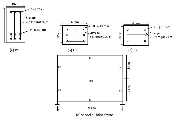
Many school buildings in Thailand are low-rise, single span type, as seen in Figure 1. The height is 2-4 stories and typical span is 9.4 meter. For the only gravity load design, the building frame is composed of small columns (30x40 cm rectangular section) connected with deep beams (30x80 cm rectangular section). This makes the designed frame behaving as the strong beam-weak column under a strong earthquake. Seismic vulnerability of the school building was studied and the strengthening using the concrete infilled steel tube in haunch zones was proposed Hansapinyo et al. (2018Hansapinyo, C., Buachart, C. and Chaimahawan, P. (2018). Tests of inclined concrete-filled steel tubular stub columns under vertical cyclic loading. Advances in Civil Engineering, Vol. 2018, Article ID 5426731, 9 pages.). The studies indicated the very low seismic capacity due to the joint and column weakness. Hence, seismic strengthening requirement was concluded in the studies.
(a) Beam section, (b) and (c) Column Sections, (d) School building frame (Hansapinyo et al., 2012Hansapinyo, C., Sagolvitayanont, W., and Matsushima, M. (2012). Seismic strengthening with externally bonded FRP of low-rise, single span reinforced concrete buildings. In Proceeding of the First Australasia and South-East Asia Structural Engineering and Construction Conference (ASEA-SEC-1), Perth, Australia.)
Seismic strengthening of the beam-column joint is a challenging task. Many efficient methods have been proposed but only some of them are practically implemented. Drilling to insert more rebar increase the joint strength but working on site is complicated and destructive. To avoid the joint drilling, Esmaeeli et al. (2017Esmaeeli, E., Danesh, F., Tee, K. F., and Eshghi, S. (2017). A combination of GFRP sheets and steel cage for seismic strengthening of shear-deficient corner RC beam-column joints. Composite Structures, 159: 206-219.) strengthened reinforced concrete beam-column joint using Glass Fiber Reinforced Polymer (GFRP) with angle steel cages. The merit of using this method is that there is no beams or columns are drilled. However, for the small joint area, enhancing the core joint strength area is limited. Hence, enlarging the joint area is considered as a more effective method. Sharma et al. (2014Sharma, A., Eligehausen, R., and Hofmann, J. (2014). Numerical modeling of joints retrofitted with haunch retrofit solution. ACI Structural Journal, 111(4): 861-872.) performed a simulation of joint strengthening by increasing the area using Fully Fastened Haunch Retrofit Solution (FFHRS). As the joint shear strength was substantially increased, this method relocated the yielding point to the beam. In Shafaei et al. (2014Shafaei, J., Hosseini, A., and Marefat, M. S. (2014). Seismic retrofit of external RC beam-column joints by joint enlargement using prestressed steel angles. Engineering Structures, 81: 265-288.) and Adibi et al. (2017Adibi, M., Marefat, M. S., Esmaeily, A., Arani, K. K., and Esmaeily, A. (2017). Seismic retrofit of external concrete beam-column joints reinforced by plain bars using steel angles prestressed by cross ties. Engineering Structures, 148: 813-828.) works, exterior reinforced concrete beam-column joints were tested. The beam-column joints were upgraded by using the steel bars and prestressed cross ties around the joints. The results of the study indicated the ability of the seismic strengthening method to prevent damage at the connection and increased the hysteresis energy capacity. However, the increasing of strength was not obtained significantly. From the study, the joint strengthening by enlarging the joint area is considered as an effective method for the small joint frame. However, the increased joint area also reduces the beam span and then increase the beam capacity. Therefore, the study introduces the increase of joint shear capacity using externally attached steel column. Four exterior reinforced concrete frames with small column and small joint were tested under cyclic loading. Then, the same test of one seismic upgrading of the similar exterior reinforced concrete frame using externally attached steel column was performed. Finally, the upgrading method for the frame with the small column and the small joint is discussed in terms of the strength and ductility.
2 SPECIMENS AND METHODS
2.1 Specimens
There were 5 test specimens as shown in Figure 2. The first four specimens were exterior reinforced concrete frame designed to be failed by the joint shear failure. Their nomenclature starts by “M” letter. The other one specimen was the upgraded exterior reinforced concrete frame. The nomenclature starts by “U” letter. The test specimens were planar beam-column subassemblies representing a portion of the building frame at the exterior joint between column and beams. The cyclic force was applied so that the distribution of the bending moment and shear force in the specimens were the same as for the whole building frame under lateral cyclic loading (Ketiyot & Hansapinyo, 2018Ketiyot, R., and Hansapinyo, C. (2018). Seismic performance of interior precast concrete beam-column connections with T-section steel inserts under cyclic loading. Earthquake Engineering and Engineering Vibration, 17(2): 355-369.). Specimens M1, M2, and M3 were a group of similar test specimens. The only difference was the reinforcement at the joint. The upgraded specimen U5 using attached steel column had sectional dimension and reinforcement similar to M4 specimen. The steel column was a 12.5x12.5 cm square steel box with a thickness of 3.2 mm. Longitudinal reinforcement was SD40 deformed bar either DB12 or DB16 with the nominal diameter of 12 mm and 16 mm, respectively. The stirrup was SR24 round bar either RB6 or RB9 with the nominal diameter of 6 mm and 9 mm, respectively. The tensile test results of the steels are shown in Table 1. At the cast date, concrete cylinders were sampled and tested for the compressive strength at the same date of the frame test. The concrete compressive strengths of the specimens are shown in Table 2.
The first group of specimens comprising of M1-M3 were designed for the joint shear critical to obtain the effect of the different joint detailing. As shown in Figure 2, there was no hoop reinforcement in the joint area for M1 specimen. Three stirrups were provided for M2 specimen and diagonal rebars were arranged for M3 specimen. However, the contribution of the reinforcement is ignored for the determination of the joint shear strength based on chapter 21.7.4 of ACI318 (ACI, 20008), as seen in equation (1), whereand are respectively the concrete compressive strength and the effective cross-sectional area within a joint in a plane parallel to plane of reinforcement resisting shear in the joint. For M4 specimen, the exterior joint had no shear reinforcement resemble with M1 specimen but the column size was smaller. The reinforcement and dimensions of M4 specimen were designed considering strength scaling based on the capacity of the school building frame, as shown in Figure 1. The calculated ultimate story shear was 13.10 kN, as shown in Table 2, with the joint failure mode. For specimen U5, 12.5x12.5x0.32 cm hollowed steel box column was externally attached to the column to increase the column and shear capacity. As shown in Figure 2(f), to attach the steel box into the exterior existing column, two steel plates were attached to the column at the two ends using four drilled bolts. Then, the column was welded to the steel plate. At the beam-column joint, the covering concrete of the hook bar was removed and the hooks of the longitudinal reinforcement were straightened out and welded to the attached steel box. The required strength of the steel box was determined based on the capacity design philosophy. As shown in Figure 3, the capacity for different failure modes are first determined (Steps 1-3) and then calculate the ultimate story shear for the different modes (Step 4). Next, aiming at altering failure to the flexural damage in the beam, the required more strength upgrade for each mode is estimated based on the exiting flexural capacity of the beam. For upgraded specimen U5, the calculated story shear is 33.60 kN, as shown in Table 2, with the failure mode is altered to the shear failure in the column at the section next to the end of the attached steel box. It is noted that, to achieve the alteration of the failure to the beam flexure, the beam shear capacity, column shear and joint shear must be upgraded to a capacity higher than the beam bending capacity by using a larger size of the steel box and extended through the column length.
2.2 Test setup
To simulate the earthquake loading during the test, ACIT 1.1-01 (ACI Innovation Task Group 1 and Collaborators, 2001ACI Innovation Task Group 1 and Collaborators. (2001). Acceptance criteria for moment frames based on structural testing (Tl.l-01) and commentary (Tl.1R-Ol), American Concrete Institute, Farmington Hills, MI.) structural testing was adopted. As shown in Figure 4(a), a subframe of the exterior beam-column joint is subjected to the lateral cyclic force P at the column top end leading to the deformation represented by the dash line. The drift ratio defined as the angle change of the column () is adopted as the loading increment. For the lateral deflection at the column tip ΔH and the column height H, the drift ratio is determined as ΔH/H.
In this study, however, vertically cyclic loading was applied at the beam end under the drift ratio control (Figure 5), as shown in Figure 4(b). Hinge supports were arranged at the top and bottom of the columns. Hence, based on the frame deformation configuration, the lateral displacement controlled at the column end (ΔH in Figure 4(b)) was converted to the vertical displacement at the beam end for the loading increment. In addition, the applied lateral load (in Figure 4(a)) was obtained considering the force equilibrium of the test frame system with the applied force (in Figure 4(b)), as seen in equation (2). It is noted that there was no compressive load applied at the column of the specimens as the low-rise building is subjected to a small magnitude of the axial load. In addition, the strength of the beam-column joint is less compared with the column having a certain amount of compressive load leading to a conservation study for the joint strengthening.
3 RESULTS AND DISCUSSIONS
3.1 Failure mode and hysteresis behavior
The relationship between the story shear () and the drift ratio () of the specimens are shown in Figure 6. The cracking and the hysteresis behavior of all specimens were similar. For the sake of the explanation, the cracking propagation of M1 specimen is shown with the hysteresis curve (the first graph of Figure 6). At the early loading with the drift ratio less than 0.2%, the stiffness was maintained constant. Then, the first flexural crack at the beam end near the column face was occurred leading to the reduction of the stiffness (Point “A”). With the increase of the drift ratio, the flexural crack was lengthened and widened. New flexural cracks in the beam were generated at sections far from the column face. Diagonal cracks in the beam-column joint also were found. However, for M4 and U5 specimens, there were only a few cracks in the beam. After the occurrence of the diagonal cracks in the beam-column joint, the further increased of the drift ratio increased the damage at the joint area, deteriorated the stiffness. The area under the relationship was decreased and the pinching effect was obviously demonstrated (Loading range “B”). The peak story shears were obtained at about the drift ratio of 1.4% with the formation of the wedge formed crack at the joint (Point “C”). With the further increase of the drift ration, the generated cracks were widened and concrete spalling was observed (Point “D”). For U5 specimen, shear crack at the bottom column was found at the section next to the externally attached steel box. Figure 7 shows the crack pattern of U5 specimen. Figure 8 shows the crack development of all specimens. Hence, as the failure mode was brittle, the energy dissipation capacity of the specimens was quite limited. The failure mode of M1-M4 specimens was the beam-column joint failure. However, it is noted that M2 specimen test was stopped accidentally at the post peak loading due to the improperly loading alignment.
3.2 Reinforcement strains
Strain gauges were attached to the reinforcement at the expected critical sections as shown in Figure 9. Some strain values obtained during the tests are shown in Figure 10. The strains in the longitudinal beam reinforcement at the column face are smaller than the yield strains shown in Table 1. The strain the joint shear reinforcement (M3-STG6) is also small. Hence, the contribution of the shear reinforcement to resist the joint shear force is negligible.
3.3 Envelop curve, Strength and ductility
To determine the ductility of the specimen under the cyclic loading, the envelop curve of the relationship between story shear - drift ratio is drawn. The Ductility () indicates the ability to maintain load carrying capacity of a structure after reaching the ultimate capacity. As seen in equation (3), the ductility is determined as the ratio between the ultimate drift ratio () to the yield drift ratio ()
Based on the research of Legeron & Paultre (2000Legeron, F., and Paultre, P. (2000). Behavior of high-strength concrete columns under cyclic flexure and constant axial load. Structural Journal, 97(4): 591-601.), the yield drift ratio and the ultimate drift ratio can be defined, as shown in Figure 11. First, the 0.75 of the ultimate story shear (0.75) is determined and a line from the origin to the 0.75 story shear to meet the ultimate story shear at point “a” is drawn. Then, the yield drift ratio can be defined corresponding to the point “a”. For the ultimate drift ratio, it is defined as the drift ratio at the after peak story shear of 0.80 (point “b”). The envelop curves of the specimens are shown in Figure 12. Considering the smaller loading capacity between the push and pull sides, the story shear capacities of the specimens are shown in Table 3. The story shear of M1, M2 and M3 specimens were 29.0 kN, 35.0 kN and 24.4 kN., respectively. For M4 specimen, the story shear capacity was only 18.6 kN. The upgraded U5 specimen possessed the story shear capacity of 37.5 kN which is 2.02 times of the strength of M4 specimen. The comparison ratio of the ultimate story shear between the test and calculation are in the range of 0.64-1.42. The calculation is overestimated for the first group of specimens (M1-M3) and underestimated for the small column specimens (M5 and U5). The smaller ductility of the push and pull sides are shown in Table 3. As all the specimens were failed by the brittle failure modes, the ductility of the specimens is quite small values (2.02-4.54).
Determination of ductility (Legeron & Paultre, 2000Legeron, F., and Paultre, P. (2000). Behavior of high-strength concrete columns under cyclic flexure and constant axial load. Structural Journal, 97(4): 591-601.)
4 CONCLUSIONS
In this research, five exterior reinforced concrete beam-column were tested. The results of the tests can be summarized as follows.
-
For the first three specimens M1, M2, M3, the effect of joint reinforcement to increase the joint strength is almost negligible. The concrete strength contributed an important role to resist the joint shear which is agreed with the joint shear strength calculation of ACI318. This is due to the small area of the joint zone. However, although the ductility of the three specimens is not much different, the reinforcement reduced the severity of the damage at the larger drift ratio.
-
Considering M4 specimen with the very small column compared with the connecting beam, the column was failed at a very low story shear. As the joint area is also very small, the column failure was immediately followed by the joint shear failure. There were no damages in the connecting beam. Hence, the externally attached steel column the exterior was introduced in U5 specimen. The result of the installation increased the story shear from 18.6 kN. of M4 specimen to 37.5 kN of U5 specimen which is 2.02 times higher. However, the ductility is needed to be improved as the failure of U5 specimen was the column failure.
-
For a single span low-rise reinforced concrete frame, with low cumulative gravity load on the column and large span beam, the frame is composed of the very small column connected with the large beam. The seismic strengthening of U5 specimen using the externally attached steel column is considered as an effective method. It increases the column and joint shear capacities without damaging the joint area. In addition, the beam capacity is not increased. Hence, the designed for the seismic upgrade can alter the failure mode to the beam flexure.
5 ACKNOWLEDGEMENTS
The authors would like to acknowledge Faculty of Engineering, Chiang Mai University for supports under Research Assistant scholarship (RA) and the Graduate School of Chiang Mai University for financial support under Teacher Assistant and Research Assistant scholarship (TA/RA). The experiment of this project is financially supportted by TRF Senior Research Scholar (RTA62).
References
- ACI Innovation Task Group 1 and Collaborators. (2001). Acceptance criteria for moment frames based on structural testing (Tl.l-01) and commentary (Tl.1R-Ol), American Concrete Institute, Farmington Hills, MI.
- Adibi, M., Marefat, M. S., Esmaeily, A., Arani, K. K., and Esmaeily, A. (2017). Seismic retrofit of external concrete beam-column joints reinforced by plain bars using steel angles prestressed by cross ties. Engineering Structures, 148: 813-828.
- Arslan, M. H., and Korkmaz, H. H. (2007). What is to be learned from damage and failure of reinforced concrete structures during recent earthquakes in Turkey? Engineering Failure Analysis, 14(1): 1-22.
- Aycardi, L.E., Mander, J.B., and Reinhorn, A.M. (1994). Seismic resistance of reinforced concrete frame structures designed only for gravity loads: experimental performance of subassemblages. ACI Strutural Journal, 91(5): 552-563.
- Esmaeeli, E., Danesh, F., Tee, K. F., and Eshghi, S. (2017). A combination of GFRP sheets and steel cage for seismic strengthening of shear-deficient corner RC beam-column joints. Composite Structures, 159: 206-219.
- Gautam, D., and Chaulagain, H. (2016). Structural performance and associated lessons to be learned from world earthquakes in Nepal after 25 April 2015 (MW 7.8) Gorkha earthquake. Engineering Failure Analysis, 68: 222-243.
- Hansapinyo, C., Buachart, C. and Chaimahawan, P. (2018). Tests of inclined concrete-filled steel tubular stub columns under vertical cyclic loading. Advances in Civil Engineering, Vol. 2018, Article ID 5426731, 9 pages.
- Hansapinyo, C., Sagolvitayanont, W., and Matsushima, M. (2012). Seismic strengthening with externally bonded FRP of low-rise, single span reinforced concrete buildings. In Proceeding of the First Australasia and South-East Asia Structural Engineering and Construction Conference (ASEA-SEC-1), Perth, Australia.
- Ketiyot, R., and Hansapinyo, C. (2018). Seismic performance of interior precast concrete beam-column connections with T-section steel inserts under cyclic loading. Earthquake Engineering and Engineering Vibration, 17(2): 355-369.
- Legeron, F., and Paultre, P. (2000). Behavior of high-strength concrete columns under cyclic flexure and constant axial load. Structural Journal, 97(4): 591-601.
- Pampanin, S., Calvi, G. M., and Moratti, M. (2002). Seismic behavior of RC beam-column joints designed for gravity only. 12th European Conference on Earthquake Engineering, London.
- Paulay, T., and Priestley, M. J. N. (1992). Seismic design of reinforced concrete and masonry buildings. John Wiley and Sons.
- Ruiz-Pinilla, J. G., Adam, J. M., Pérez-Cárcel, R., Yuste, J., and Moragues, J. J. (2016). Learning from RC building structures damaged by the earthquake in Lorca, Spain, in 2011. Engineering Failure Analysis, 68: 76-86.
- Saicheur, K., and Hansapinyo, C. (2016). Structural repair prioritization of buildings damaged after earthquake using fuzzy logic model. Journal of Disaster Research, 11: 559-565.
- Saicheur, K., and Hansapinyo, C. (2017). Seismic loss estimation and reduction after structural rehabilitation in Chiang Rai city. Walailak Journal of Science & Technology: 14(6): 485-499.
- Shafaei, J., Hosseini, A., and Marefat, M. S. (2014). Seismic retrofit of external RC beam-column joints by joint enlargement using prestressed steel angles. Engineering Structures, 81: 265-288.
- Sharma, A., Eligehausen, R., and Hofmann, J. (2014). Numerical modeling of joints retrofitted with haunch retrofit solution. ACI Structural Journal, 111(4): 861-872.
- Sharma, K., Deng, L., and Noguez, C. C. (2016). Field investigation on the performance of building structures during the April 25, 2015, Gorkha earthquake in Nepal. Engineering Structures, 121: 61-74.
- Standard, ACI (2008). Building Code Requirements for Structural Concrete (ACI 318M-08) and Commentary. Reported by ACI Committee, 318.
- Tapan, M., Comert, M., Demir, C., Sayan, Y., Orakcal, K., and Ilki, A. (2013). Failures of structures during the October 23, 2011 Tabanlı (Van) and November 9, 2011 Edremit (Van) earthquakes in Turkey. Engineering Failure Analysis, 34: 606-628.
Edited by
Editor:
Publication Dates
-
Publication in this collection
10 July 2019 -
Date of issue
2019
History
-
Received
18 Feb 2019 -
Reviewed
23 Feb 2019 -
Accepted
19 May 2019 -
Published
22 May 2019