Abstract
A well known phenomenon, the "built-up edge - BUE", occurs at the chip/tool interface when multiphase materials are machined at low cutting speeds. Under high compressive stresses, seizure prevents the material from sliding over the tool’s rake face. Although many reports have been published on the subject, studies of the BUE phenomenon have been marked by a lack of precision in determining its dimensions. This paper reports on a study of the BUE geometry of a SAE 12L14 steel machined at low speeds with and without a cutting fluid. Three quick-stop samples were prepared for each test condition (9 cutting speeds, with and without cutting fluid). The quick-stop samples were mounted perpendicularly in transparent acrylic resin to facilitate observation and the hardened resin sandpapered. The opposite face of the mounted sample was then ground to make the front and back faces parallel. After sandpapering and polishing, the samples were digitally photographed and their BUE geometries determined using an image analyzer. The measurements were done along the cutting width at five different points. It was found that the BUE dimensions varied considerably along the cutting width, and that the fluid reduced the BUE at the lowest cutting speed tested.
built-up-edge; quick-stop; SAE 12L14 steel
TECHNICAL PAPERS
Effect of cutting speed and cutting fluid on the BUE geometry of a SAE 12L14 free machining steel
Leandro L. G. ReisI; Washington M. da Silva JúniorII; Álisson R. MachadoIII
Ilacerdareis@yahoo.com, Machining Education and Research Laboratory, Federal University of Uberlândia UFU
IIwashington@mecanica.ufu.br, Tribology and Materials Laboratory, Federal University of Uberlândia UFU
IIISenior Member, ABCM, calissonm@mecanica.ufu.br, Machining Education and Research Laboratory, Federal University of Uberlândia UFU, 38400-902 Uberlândia, MG. Brazil
ABSTRACT
A well known phenomenon, the "built-up edge BUE", occurs at the chip/tool interface when multiphase materials are machined at low cutting speeds. Under high compressive stresses, seizure prevents the material from sliding over the tools rake face. Although many reports have been published on the subject, studies of the BUE phenomenon have been marked by a lack of precision in determining its dimensions. This paper reports on a study of the BUE geometry of a SAE 12L14 steel machined at low speeds with and without a cutting fluid. Three quick-stop samples were prepared for each test condition (9 cutting speeds, with and without cutting fluid). The quick-stop samples were mounted perpendicularly in transparent acrylic resin to facilitate observation and the hardened resin sandpapered. The opposite face of the mounted sample was then ground to make the front and back faces parallel. After sandpapering and polishing, the samples were digitally photographed and their BUE geometries determined using an image analyzer. The measurements were done along the cutting width at five different points. It was found that the BUE dimensions varied considerably along the cutting width, and that the fluid reduced the BUE at the lowest cutting speed tested.
Keywords: built-up-edge, quick-stop, SAE 12L14 steel
Introduction
When multiphase materials are machined at low cutting speeds, a phenomenon known as the "built-up edge BUE" may occur at the chip/tool interface. There is evidence that the BUE occurs continuously along the material of the workpiece and the chip, rather than constituting a separate body of hardened material over which the chip slides (Trent, 1963). Figure 1 shows a schematic drawing of this evidence of BUE behavior. This bond is confirmed in the micrograph in Figure 1, obtained from a quick-stop sample produced by machining an Al-Si alloy at a cutting speed of 38 m/min.
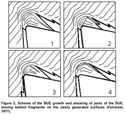
Under high compressive stresses, the bonds are sufficiently strong to prevent the material from sliding over the tools rake face. The chip is formed and moves by plastic strain toward the region above points "A" and "B" of Figure 1-a. Trent (1988) explains this phenomenon as follows: "... the first layer of the material connects to the tool through atomic bonds and workhardens, thus increasing its yield point, and the shear stresses do not suffice to break these bonds. The strains then continue spreading to the adjacent upper layers further away from the interface, until they, too, become sufficiently workhardened. Successive layers form the BUE by the repetition of this process". Trent (1963) showed that the BUE increases to a point at which the shear stress suffices to move the primary shear zone (until then above the BUE) into the body of the BUE, where its structure is sheared into parts that are dragged between the surface of the workpiece and the tools clearance, and also between the chips lower surface and the tools rake face. Figure 2 schematically depicts the process of BUE growth and the shearing of parts of it, which is a cyclic process.
It has already been proven experimentally that the BUE will only be formed in the presence of the second phase of materials being cut (Williams and Rollanson, 1970). Milovik and Wallbank (1983) explain this, theoretically, by the presence of a system of triaxial stresses in the surroundings of the strained second phases, caused by the different strain rate in the second phase in relation to the matrix. This system of triaxial stresses leads to the formation of microcracks between points A and B (Figure 1-a), which will coalesce and form larger cracks (or macrocracks) at points A and B (Figure 1-a) that are also responsible for the BUE formation.
According to Trent and Wright (2000) the difference in the relative strain of the second phase is responsible for the BUE geometry, because the promoter of microcracks disappears when it approaches the strain of the matrix, thus eliminating the BUE. Temperature plays an important role in heating and therefore softening the material of the workpiece, eliminating workhardening, which is also necessary for the formation of the BUE. The importance of temperature is demonstrated by the experimental work of Bandyopadhyay (1984), who showed that the BUE can be eliminated simply by preheating the cutting tool. This fact also explains the disappearance of the BUE as the cutting speed increases, since higher cutting speeds lead to higher cutting temperatures. Hence, the speed at which the BUE is eliminated is the "critical cutting velocity vcritical".
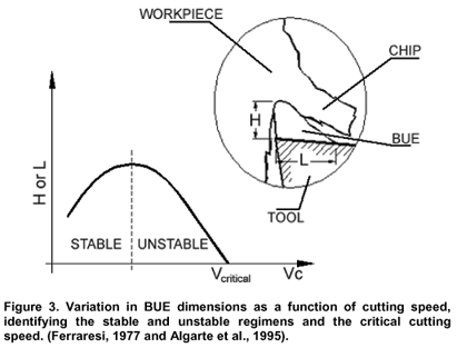
The literature states that the dimension of the BUE grows in a "stable regimen" up to a maximum value, at which point it begins to decrease in an "unstable regimen" (there is a frequency of appearance and disappearance), until it reaches the critical cutting velocity, vcritical, where the BUE disappears completely. This frequency increases as it approaches the value of the critical cutting velocity, when it disappears entirely. Figure 3 shows the variations in BUE dimensions with the cutting speed, which are normally reported in the literature according to Ferraresi (1977) and Algarte et al. (1995).
Attempt to model BUE and predict its dimension was recently published (Fang and Dewhurst, 2005). They used slip-line model which simultaneously predicts the length and height of the BUE, cutting and thrust forces, chip up-curl radius, chip thickness, and toolchip contact length.
Despite abundant publications on the subject, the study of BUE dimensions is highly compromised by the lack of precision in determining those dimensions. Da Silva (1998) demonstrated that both the width, L, and the height, H, vary greatly along the cutting width, b. This variation seriously impairs any conclusion about these curves.
The authors of the present paper also studied several quick-stop samples of Al-Si alloys in order to ascertain the influence of the cutting speed and the application of cutting fluid on the BUE dimensions. The measurements were taken at various points along the cutting width, b. In addition to finding that the average BUE dimensions decreased as the cutting speed increased and cutting fluid was applied, it was confirmed the variation in these dimensions occurring along the cutting edge. The photograph in Figure 4 illustrates this variation.
Figure 4a shows the chips lower surface, at the cutting wedge, obtained when machining an Al-Si alloy at 9 m/min. As illustrated in the figure, the width of the BUE, L1, in the central region is far greater than the width, L2, in the peripheral region of the cutting width, b (L1 > L2).
This figure also shows several fragments from the workpiece flying off the interface between the BUE and the lower surface of the chip. This is a strong indication that there is spreading of the material caused by high stresses acting in the region. This excess of BUE material can also spread through the sides of the chip. Figure 4-b shows one such situation, in which a tiny lateral fragment evolves on the free side of the chip. When that also happens on the back face, this fragment moves toward the secondary surface being machined, undoubtedly contributing to impair the surface finish of the machined workpiece.
Sliding should occur throughout the chip/tool contact region at very low cutting speeds, and in the periphery of the sticking (or seizure) zone at high cutting speeds. The BUE will be present at low and intermediary cutting speeds, while the flow zone (which is present in conditions of seizure) will form at high cutting speeds.
Thus, there are still many doubts about the process of identification and characterization of the built-up edge. This study aims to investigate the geometry of the BUE along the cutting width, which is produced in machining tests at low speeds. To this end, our attention focused on the effect of cutting speed on the formation of the BUE. Cutting fluid is known to interfere in the BUE dimensions, for it alters the thermal conditions of the chip flow by cooling the chip/tool interface and therefore it will also be considered.
Methodology
The methodology used for investigating the behavior of the chip/tool interface consists of using a device called "quick-stop". The quick-stop, coupled to an IMOR MAXII 520 lathe, was used to cylinder a bar of SAE 12L14 free machining steel having an average hardness of 115 HB and an external diameter of 73.95mm. The chemical composition of this work material is shown at Table 1.
The quick-stop mechanism has various configurations, which consist, basically, of removing the tool during cutting at a higher speed than the cutting speed, so that the machining condition prevailing when the tool was removed is maintained. This mechanism is illustrated in the diagram of Figure 5.
The working principle is simple and consists of a tool mounted on a pivoting base coupled to the lathes tool holder carriage, allowing the tool to swivel, as shown in Figure 5. The tool is pushed at high speed by mechanical energy. The cut is interrupted and the root of the chip is available for analysis, after it is sample sectioned with a manual hacksaw.
A depth of cut of 2.0 mm and a feed rate of 0.138 mm/rev were maintained constant. An uncoated cemented carbide SPUN 120308, P20 tool was used with the following geometry: gO = 6°, cr = 75°, ls = 0°.
For the quick-stop test, nine cutting speeds were chosen (see Table 2) without (dry) and with cutting fluid (5% concentration of emulsive oil), allowing for a range of lathe speeds, from low speeds up to the speed at which it is believed that the BUE is no longer present. The cutting fluid was applied by flooding.
Two repetitions were carried out under each cutting condition. Samples of the chips root were mounted in transparent acrylic resin. After mounting, the samples were sandpapered and polished, with the chip root and the front face of the sample perpendicular to each other to facilitate observation. The rear face was then ground and sandpapered to make it parallel to the front face. This procedure minimizes errors when measuring the depth of the cross-section where the BUE dimensions are measured.
The front face was sandpapered down to a granulometry of 1,000 and then polished with alumina (Al2O3) having an average diameter of 1µm.
The BUE geometry along half way of the cutting width, b, was measured based on a series of digital photographs taken of the BUEs cross-sections, using a NEOPHOT 21 optical microscope with an image acquisition system. Measurements of the BUE height (H) and area (A) were taken using the Scion Image analyzing software. The values shown here are the averages of the magnitudes measured in the three samples at each cutting speed.
A comparator gaugedial indicator (with 1µm resolution) was used for the definition of the reference depth of the samples. The first measurement of the BUE dimensions was taken as soon as a plane surface appropriate for measuring was obtained. This position was considered the reference. Using the comparator gaugedial indicator, the distance of the new observation surfaces in relation to the reference of each sample were them measured. Five measurements were taken along half way of the cutting width, b, for each sample. During this phase, the distance between the sections was kept carefully at approximately 80µm.
The three-dimensional BUE model was built using a software program called BLENDER.
Results and Discussion
Five photographs of the BUE of each sample were taken, with each photograph representing one of the samples cross-sections. Figure 6 shows the sequence of photographs taken for the machining condition in which the cutting speed was 20.91 m/min, using cutting fluid.
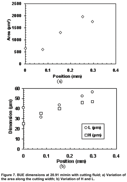
Figure 7 depicts the typical results of the variation in BUE dimensions of the sample machined at 20.91 m/min, using cutting fluid.
In this cutting condition the BUE area varied 69.6% between the highest and lowest values along the cutting width. The height (H) and width (L) varied 46.3% and 43.9%, respectively. This result matches with those found by Da Silva (1998), indicating that any attempt of generating curves representing the variations of BUE dimensions against a cutting parameter, such as the one shown in Figure 3, can only be taken for grant if their dimensional variations along the cutting width are considered.
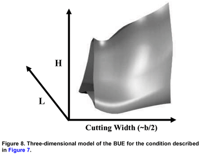
A three-dimensional model of the BUE was built based on the area of the sections, as shown in Figure 8.
The three-dimensional model provides a view of approximately how the BUE geometry is altered along the cutting width.
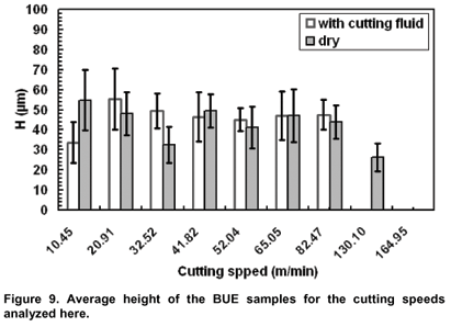
The graphs in Figures 9 and 10 indicate the results of the dimensions of H and L as a function of the cutting speed, respectively. Each point is the overall average of the three samples, with five measurements of each (total of 15 measurements).
The first thing Figures 9 and 10 reveal is the fact that the BUE dimensions of this material under the conditions tested are very small (maximum values of 70 µm for H and L). Although Trent and Wright (2000) have reported that MnS particles may prevent BUE when machining with steel cutting grades of cemented carbide tools, the results of present investigation reveal that they were able only to reduce its dimensions.
Despite the significant standard deviation, and this is clearly due to the high variation of its dimensions along the cutting width as seen in Figure 7, note that the cutting fluid affected the size of the BUE at the speed of 10.45 m/min, reducing its dimensions. The opposite held true at cutting speeds of 20.91 m/min and 32.52 m/min, i.e., cutting without fluid led to smaller BUEs. At speeds of more than 32.52 m/min, the variations in the BUE dimensions as a function of the presence of cutting fluid can be considered negligible. Although further tests are required for precise explanation of this, it can be suggested that the cutting fluid may have difficulties to exert its lubricant action at the interface at higher cutting speeds.
It was also found that the cutting fluid acted by reducing the "critical cutting velocity vcritic.al", so that, in the absence of fluid, BUEs were present in the samples machined at speeds of up to 130.10 m/min (albeit with very small dimensions of H » 25 µm, L » 50 µm), leading to the conclusion that the vcritical lies above this speed. In cutting with fluid, the BUE was found to disappear at speeds above 82.47 m/min; hence, the vcritical lay between 82.47 m/min and 130.10 m/min, indicating the cooling action of the fluid, which reduced the vcritical. This occurs because the cutting fluid acting as coolant reduces average cutting temperature and increases the material strength, consequently more heat is produced during chip formation, avoiding workhardening to prevail over heat softening, eliminating thereby the BUE.
The cutting fluid must be focused in two different actions. If lubricant action prevails it might reduce BUE dimensions. However, if cooling action prevails the opposite is true. In case of a balance between these two actions the cutting fluid may not change the BUE dimensions. This might explains the influence of the cutting fluid in figures 9 and 10.
The graph in Figure 11 illustrates the variation of the BUE geometry with the cutting speed, represented by the measurement of its area.
It was found that the analyses of L and H held true, and that the values of the standard deviations at each speed showed an increase, which suggests that measuring the BUE area is a more sensible way of analyzing its geometry. Based on this method, the results indicate that the BUE dimensions do not necessarily follow the behavior depicted in Figure 3, as suggested in the literature (Ferraresi, 1977 and Algarte et al., 1995).
Conclusions
The methodology developed here allows for the analysis of variations in the BUE dimensions along its cutting width.
The use of cutting fluid proved efficient in reducing the BUE only at low cutting speeds.
It was found that, for the SAE 12L14 steel, the dimensions of the BUE are small and that its geometry varies considerably along the cutting width, and that under some conditions, the largest measured area is four-fold larger than the smallest.
In this study, it was found that measuring the BUE area (A) can be considered a good methodology to analyze the BUE, since the results obtained showed the same characteristics as those found with H and L. It was also found that measuring the BUE area may reduce errors in measurement, since the area is measured using an image analyzer with specific tools, while there is no standardized way of measuring the H and L. This means that various data reported in the literature are meaningless unless they are accompanied by an identification of the point where the measurements were taken along the cutting width, b.
BANDYOPADHYAY, B.P. Mechanism of Formation of Built-up Edge. In: Precision Engineering, July 1984. vol. 6(3), pp. 148-151.
Da SILVA, M.B. Lubrication in Metal Cutting under Built-up-Edge Conditions. 1998. PhD Thesis, University of Warwick, England, UK, October.
FERRARESI, D. Fundamentos da Usinagem dos Metais. São Paulo: Editora Edgard Blücher Ltda, 1977. 751 págs.
FANG, N.; DEWHURST, P. Slip-line Modeling of Built-up edge Formation in Machining, 2005, International Journal of Mechanical Science, vol. 47, issue 7, July, pp 1079-1098.
MILOVIK, R.; WALLBANK, J. The Machining of Low Carbon Free Cutting Steels with High Speed Steel Tools. 1983. The Machinability of Engineering Materials, ASM, pp. 23-41.
SHAW, M.C.; NAKAYAMA, K. Relationship Between Cutting Forces, Temperatures, Built-up Edge and Surface Finish. 1966. Annals of the C.I.R.P. vol. 24, pp. 211-223.
SUKVITTAYAWONG, S.; INASAKI, I., Detection of Built-up Edge in Turning Process. 1994. Int. J. Mach, Tools Manufact. vol. 34, pp. 829-840.
TRENT, E.M. Cutting Steel and Iron with Cemented Carbide Tools - Part II: Conditions of Seizure at the Tool/Work Interface. 1963. Journal of the Iron and Steel Institute, Nov. 1963, pp. 923-932.
TRENT, E.M. Metal Cutting and the Tribology of Seizure: II-Movement of Work Material Over the Tool in Metal Cutting. 1988. Wear, vol. 128, pp. 47-64.
TRENT, E.M.; WRIGHT, P.K. Metal Cutting. 2000. 4th Edition, Butterworth Heinemann, ISBN 0-7506-7069-X, 446 págs.
YAGUCHI, H. Effect of Soft Additives (Pb, Bi) on Formation of Built-Up Edge. 1988. Wear, vol. 4, pp. 926-930.
WALLBANK, J. Structure of Built-up Edge Formed in Metal Cutting. 1979. Metals Technology, April, pp. 145-153.
WILLIAMS, J.E.; ROLLANSON, E.C. Metallurgical and Pratical Machining Parameters Affecting Built-up Edge Formation in Metal Cutting. 1970. J. Inst. Metals, vol. 98, pp. 144-153.
Paper accepted Novembe, 2006.
Technical Editor: Anselmo E. Diniz.
- ALGARTE, R.D.; Da SILVA, M.B.; MACHADO, A.R. Morfologia da APC no Torneamento do Aço ABNT 1020. 1995. Anais do XIII COBEM, Belo Horizonte, December, (CD ROM).
Publication Dates
-
Publication in this collection
03 Sept 2007 -
Date of issue
June 2007
History
-
Received
Nov 2006 -
Accepted
Nov 2006


