Abstract
This paper investigates the axial crushing response of concentric expanded metal tubes under impact loading. The study is conducted by means of nonlinear finite element simulations, considering the speed of deformation and the size of the expanded metal cells. In the analysis, two tubes are placed concentrically and then axially crushed with an impact mass at various speed levels. Crushing load-displacement responses are analyzed to investigate the influence of the size of the mesh and the impact speed. The results show that specimens with the same mesh sizes increases their crushing length with increasing speed. Finally the main outcome of this investigation is to add to the state of knowledge information concerning the use of expanded metal meshes in impact attenuation devices.
Keywords:
Impact loading; axial crushing; expanded metal; collapse modes
1 INTRODUCTION
Expanded metal meshes have been widely used in the industry for decorative purposes, protective and staircase systems. In spite of the growing number of patents developed every year (Smith et al. 2009aSmith, D., Graciano, C., Martínez, G., (2009). Recent patents on expanded metal. Recent Patents on Materials Science 2(3);209-25.), research projects concerning their structural behavior are still limited. As seen in previous works (Graciano et al. 2009Graciano, C., Martínez, G., Smith, D., (2009). Experimental investigation on the axial collapse of expanded metal tubes. Thin-Walled Structures 47:953-61., Smith et al. 2014Smith D, Graciano C, Martínez G, Texeira P., (2014a). Axial crushing of flattened expanded metal tubes. Thin-Walled Structures 85:42-49.), tubes fabricated with expanded metal meshes are feasible alternatives for energy absorption applications due to their collapsibility.
Commonly, lightweight structural members subjected to compressive loads exhibit good collapsibility, nevertheless this feature is compromised by geometric and material imperfection sensitivities that reduces their carrying capacity. To guarantee a stable and progressive collapse the members need enough material availability for plastic deformation. It can be achieved by adding more tubes, while keeping the thickness small. Therefore, placing or nesting tubes concentric or eccentrically is also a feasible alternative to enhance the performance of energy absorbers (Haghi et al. 2013Haghi, M., Shahsavari, H., Akbarshahi, H., Shakeri, M., (2013). Bitubular square tubes with different arrangements under quasi-static axial compression loading. Materials and Design 51:1095-103.). Lately, Nia et al. (2015Nia, A.A., Khodabakhsh, H., (2015). The effect of radial distance of concentric thin-walled tubes on their energy absorption capability under axial dynamic and quasi-static loading, Thin-Walled Structures 93:188-197., 2016aNia, A.A., Chahardoli, S., (2016a). Mechanical behavior of nested multi-tubular structures under quasi-static axial load. Thin-Walled Structures 106:376-389., 2016bNia, A.A., Chahardoli, S., (2016b). Optimizing the layout of nested three-tube structures in quasi-static axial collapse. Thin-Walled Structures 107:169-181.) investigated the energy absorption characteristics of nested multi-tubular structures. Inserting foam between the tubes modify the deformation patterns and smooth the instable responses (Zhang et al. 2010Zhang, Z., Liu, S., Tang, Z., (2010). Crashworthiness investigation of kagome honeycomb sandwich cylindrical column under axial crushing loads. Thin-Walled Structures 48(1):9-18., 2012Zhang, Y., Sun, G., Li, G., Luo, Z., Li, Q., (2012). Optimization of foam-filled bitubal structures for crashworthiness criteria. Materials and Design 38:99-109.; Niknejad and Orojloo 2016Niknejad, A., Orojloo, P.H., (2016). A novel nested system of tubes with special cross-section as the energy absorber. Thin-Walled Structures 100:113-123.).
Nested tubes may be placed transversally, in inventive configurations, for crashworthy applications (Morris et al. 2006Morris, E., Olabi, A.G., Hashmi, M.S.J., (2006). Analysis of nested tube type energy absorbers with different indenters and exterior constraints. Thin-Walled Structures 44:872-85., 2007Morris, E., Olabi, A.G., Hashmi, M.S.J., (2007). Lateral crushing of circular and non-circular tube systems under quasi-static conditions. Journal of Materials Processing Technology 191:132-35.; Baroutaji et al. 2016Baroutaji, A., Gilchrist, M.D., Olabi, A.G., (2016). Quasi-static, impact and energy absorption of internally nested tubes subjected to lateral loading. Thin-Walled Structures 98B:337-350.). By placing the tubes transversally, the energy absorption mechanism changes from axial crushing to a bending mechanism. Several assets are achieved using these type of tubes, for instance the possibility of nesting an array of tubes of various diameters reducing the occupied space, and furthermore the tubes may undergo additional deformation to obtain oblong configurations which allow larger crushing displacements than for circular ones (Baroutaji et al. 2014Baroutaji, A., Morris, E., Olabi, A.G., (2014). Quasi-static response and multi-objective crashworthiness optimization of oblong tube under lateral loading. Thin-Walled Structures 82:262-77.).
Martínez et al. (2013Martínez, G., Graciano, C., Teixeira, P., (2013). Energy absorption of axially crushed expanded metal tubes. Thin-Walled Structures 71:134-46.) investigated numerically the energy absorption capacity of concentric expanded metal tubes using the same cell orientation. Afterward, Smith et al. (2014Smith, D., Graciano, C., Martínez, G., (2014b). Quasi-static axial compression of concentric expanded metal tubes. Thin-Walled Structures 84:170-176.) conducted an experimental investigation on the quasi-static response of concentric expanded metal tubes with various cell orientations, the results showed that the deformation pattern of the tubes changes significantly due to interaction between collapse modes for the inner and outer tubes.
Recently, Nouri et al. (2015Nouri, M.D., Hatami, H., Jahromi, A.G., (2015a). Experimental and numerical investigation of expanded metal tube absorber under axial impact loading. Structural Engineering and Mechanics, 54(6):1245-1266.) performed an experimental and numerical study on the response of expanded metal absorbers subjected to low speed impact. Subsequently, Hatami and Nouri (2015Hatami, H., Nouri, M.D. (2015b). Experimental and numerical investigation of lattice-walled cylindrical shell under low axial impact velocities. Latin American Journal of Solids and Structures, 12(10):1950-1971.) also conducted a study on the energy absorption characteristics of multi-walled expanded metal energy absorbers considering a single cell orientation. Abdelaal and Tarlochan (2015Abdelaal, A.H.A., Tarlochan, F., (2015). Numerical simulation of a novel expanded metal tubular structure for crashworthiness application. In IOP Conference Series: Materials Science and Engineering Vol. 100, No. 1, p. 012063. IOP Publishing. (http://iopscience.iop.org/article/10.1088/1757-899X/100/1/012063/meta.)
http://iopscience.iop.org/article/10.108...
) investigate the response of the tubes for crashworthiness applications. Graciano et al. (2016Graciano, C., Martínez, G., Saavedra, E., (2016). Effect of elastoplastic behavior on the impact response of expanded metal tubes. DYNA, 83(198):102-109.) studied numerically the effects of the elastoplastic behavior of the material and impact speed on the response of expanded metal tubes. Furthermore, combining design of experiments techniques and finite element simulations, Borges et al. (2016Borges, H., Martínez, G., Graciano, C., (2016). Impact response of expanded metal tubes: A numerical investigation. Thin-Walled Structures 105:71-80.) studied also the impact response of these tubes. Summing up, the outcomes of these investigations show that the size and orientation of the expanded metal cells, and the impact velocity are the most influential parameters affecting the energy absorption response of expanded metal tubes.
As seen previously in the literature review, the behavior of expanded metal tubes in impact scenarios still requires further investigation. Therefore, this paper aims at investigating numerically the axial crushing response of concentric expanded metal tubes under impact conditions. Then, a parametric analysis considering the size and orientation of cells as well as the impact velocity is performed using nonlinear finite element modeling. The numerical procedure for the impact scenario is validated with previous studies taken from the literature.
2 FINITE ELEMENT MODELLING
2.1 Numerical Modeling for Expanded Metal Tubes
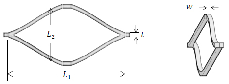
Expanded metal sheets are manufactured in a single process upon in-line expansion of partially slit metal sheets producing diamond like cells as shown in Figure 1 (EMMA 2015Expanded Metal Manufacturers Association (EMMA). Division of the National Association of Architectural Metal Manufacturers (NAAM) “EMMA 557-12: Standards for expanded metal”, 2012.). These cells are composed by strands and connecting nodes. Figure 1 shows a schematic view of an expanded metal cell, in which w is the strand width; t is the strand thickness, L2 and L1 are the minor and major cell axes, respectively.
To predict the axial crushing response of the concentric expanded metal tubes subjected to impact loading, the explicit nonlinear finite element code ANSYS AUTODYN (2010ANSYS AUTODYN User’s Manual Theorеtical manual, ANSYS Inc. Southpoint, 275 Technology Drive, Canonsburg, PA, USA, 2010.) is used herein. Individual cells in the tubes are modeled using 4-nodes tetrahedral solid elements (SOLID 164) suitable for modeling plasticity and large strain analyses. Figure 2 shows a typical mesh for an expanded metal cell. The contact between the rigid plates and the tube, and the self-contact between the strands of expanded metal as the tube collapses are taken into account using a penalty method based algorithm (ANSYS 2009ANSYS, Inc, ANSYS Release 12.0 Elements Reference, USA. 2009.). To simplify the numerical model all surface contacts in the model were treated as frictionless.
The material used to model the expanded metal tubes is an ASTM A-569 steel, hence the following material properties are considered: Young’s modulus E= 205GPa and Poisson ratio v= 0.3; quasi-static yield stress σy = 250MPa; hardening coefficient k= 495.35MPa; and strain-hardening coefficient n=0.21. These values were obtained experimentally in (Sanchez 2005Sánchez, R., (2005). Determinación de las Propiedades Mecánicas de Láminas de Metal Expandido, Master Thesis, Coordinación de Postgrado en Ingeniería Mecánica, Universidad Simón Bolívar, Caracas, Venezuela [In Spanish].). An elastoplastic model was used to reproduce the steel properties of the expanded metal cells. In the elastic range, the material is assumed homogeneous, linear and isotropic, and in the plastic range, isotropic hardening is taken into account. Therefore, the hardening curve of the material can be described employing the Hollomon correlation:
In Eq. (1), the plastic stress (σp) is expressed as a function of the plastic deformation (εp), the hardening coefficient k and the hardening exponent n. Furthermore, the effect of the strain rate of the material is taken into account in the numerical model by implementing the Cowper - Symonds correlation (Cowper and Symonds 1957Cowper G.R, Symonds P.S., (1957). Strain-hardening and strain-rate effects in the impact loading of cantilever beams, Brown University Division of Applied Mathematics, Providence, Rhode Island, USA.) shown in equation
From Eq. (2), σy
d is the dynamic yield stress at a uniaxial plastic deformation rate Abramowicz and Jones 1984Abramowicz, W., Jones, N., (1984). Dynamic axial crushing of square tubes. International Journal of Impact Engineering 2(2):179-208.). Hence, the final plasticity model, considering Eqs. (1) and (2), is provided in Eq. (3), which expresses the magnitude of the stress or yield surface for the isotropic hardening of the material , σy is the static yield stress and D and q are material constants. For low carbon steels such as the one investigated herein, the corresponding values for D=6844s-1 and q=3.91 can be used (
Figure 3 shows a schematic view of the boundary conditions considered in the numerical model. Accordingly, the nodes at the bottom of the tube are fully clamped, while the nodes on the impacted end move only in the vertical direction allowing axial crushing. The impact mass m has an initial speed V towards the impacted end of the tube, which is initially stationary. The impact mass and the base of the tube are modeled as rigid square plates (180x180mm), using 4-nodes hexahedral solid elements, with an infinite stiffness, in order to account mass inertial effects only. In the numerical analyses, all the concentric tubes were constrained to an outer tube with a mesh oriented at α = 0° (Figure 4a), and an inner tube with a mesh oriented at α = 90° (Figure 4b). Tube orientation is referred to the direction of the major axis of the cells.
Schematic view and boundary conditions used in the numerical model of the concentric tubes.
The numerical procedure used herein has been validated using the results from the investigation performed by Nagel and Thambiratnam (2004Nagel G.M, Thambiratnam D.P., (2004). A numerical study on the impact response and energy absorption of tapered thin-walled tubes. International Journal of Mechanical Sciences 46:201-16.) on the dynamic response of tapered thin-walled rectangular tubes. For details, the reader are encouraged to read about the impact response of single expanded metal tubes in Borges et al. (2015Borges, H., (2015). Caracterización de la fuerza de colapso en tubos de metal expandido sometidos a cargas de impacto, Master Thesis, Coordinación de Postgrado en Ingeniería Mecánica, Universidad Simón Bolívar, Caracas, Venezuela [In Spanish]. http://www.bib.usb.ve/tesis/000168137.pdf
http://www.bib.usb.ve/tesis/000168137.pd...
, 2016Borges, H., Martínez, G., Graciano, C., (2016). Impact response of expanded metal tubes: A numerical investigation. Thin-Walled Structures 105:71-80.). In this work, a further convergence analysis was performed for tubes with meshes H23A (Table 1) subjected to an impact mass travelling at a speed V=10 m/s. The final mesh has 10230 elements, 3585 with an average size of 5.4 mm for the outer tube, and 6645 with an average size of 7 mm for the inner one.
2.2 Parametric Analysis
Table 1 shows the dimensions of the three expanded metal cells analyzed herein. The finite element models were built according to the cell orientation, for α = 0° the models have 4 cells in the radial direction and for α = 90° the models have 6 cells. The length of the tubes is approximately three times their diameter.
Using the dimensions of the cells presented in Table 1, six numerical models (one for each single tube) were built to obtain three concentric tubes, i.e. 3 for the outer and 3 for the inner tubes. Each concentric tube was created using the same mesh type for outer and inner tubes. Table 2 shows the corresponding dimensions of the tubes, in which L is total length of the tubes, ∅e and Ne are the diameter and number of cells of the outer tube, respectively. Correspondingly, ∅i and Ni are the diameter and number of cells of the inner one.
It is important to notice that the tubes with α = 90° were placed inside the tubes with α = 0°. In previous studies (Smith et al. 2014Smith, D., Graciano, C., Martínez, G., (2014b). Quasi-static axial compression of concentric expanded metal tubes. Thin-Walled Structures 84:170-176., Hatami and Nouri 2015Nouri, M.D., Hatami, H., Jahromi, A.G., (2015a). Experimental and numerical investigation of expanded metal tube absorber under axial impact loading. Structural Engineering and Mechanics, 54(6):1245-1266.), it was found that tubes with α = 90° fail due to barreling of the cross section, i.e. outward buckling of the tube walls. Therefore, outer tubes with (= 0° restrict the buckling deformation of the inner tubes, enhancing both the load-carrying capacity and the energy absorbed of the concentric tubes. All tubes underwent impact loading using a mass m=100 kg, and the impact speed was varied from V=10m/s to V=30m/s. Figure 5 show a plan view of the arrangement for the concentric tubes.
3 RESULTS AND DISCUSSION
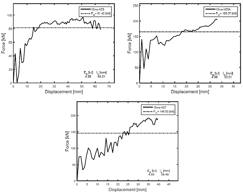
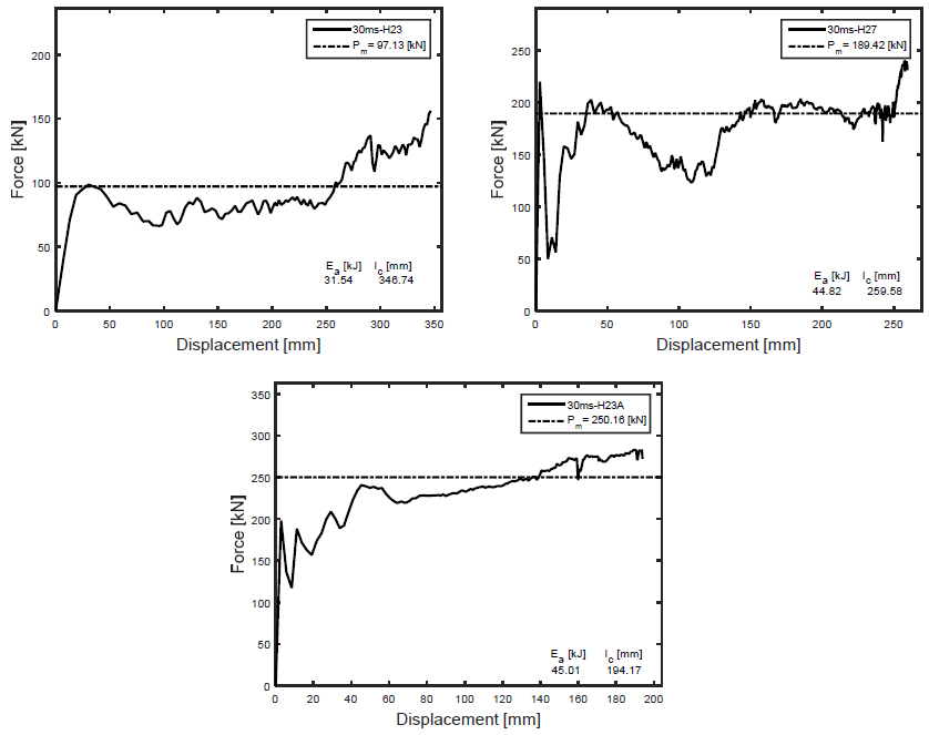
Figures 6 to 8 shows the load-displacements responses obtained numerically for the concentric tubes described in Table 2 as a function of the impact speed V. From these curves, the following parameters were calculated: mean load (Pm ) and the absorbed energy (Ea ), and the crushing length (lc ). All these parameters are calculated up to a crushing length lc that varies for each geometry.
The mean crushing force Pm , based on the area under the curve over the crushing distance lc , is calculated by
Then, the absorbed energy is calculated integrating the load-displacement curves as
where P is the measured crushing force.
Figure 6 shows the load-displacement responses for a speed V=10 m/s. It is observed that the impact speed affects the maximum crushing length of the three tubes. It is obvious that an increasing speed represents an increase in the kinetic energy to be absorbed. Concentric tubes with the smaller mesh H23 achieves the largest crushing length (lc = 64.01 mm), the tube is highly deformed since there is not enough material for plastic deformation to absorb the kinetic energy of the mass. The shortest crushing length is attained for tube with mesh H23A (lc = 33.01 mm) with larger cross-section than that of mesh H23.
Figure 7 and 8 show the load-displacement responses for speeds of V=20 m/s and V=30 m/s, respectively. There is an increasing crushing length for an increasing speed. Once again the larger crushing length is attained by the tube with the smallest mesh H23. Computed values for the crushing length are also presented in Table 3.
All responses exhibit fluctuations due to the dynamic behavior of the material. However when the displacements attain the crushing length lc , the tube is almost compacted and the compression space is utilized, giving a rise in the crushing force.
As seen in Table 3, all tubes are capable to fully absorb the kinetic energy for V=10 m/s (Ek = 5 kJ) and V=20m/s (Ek = 20 kJ). For V= 30 m/s, tube H23A is the only one capable to absorb the impact (Ek = 45 kJ) with a reasonable crushing length. For tube H23, it is physically impossible to withstand the impact at V=30 m/s, the absorbed energy was Ea = 31.54 kJ since the required crushing length is larger than its actual length.
The differences in the crushing length is mainly attributed to the amount of material in the cross section area. H27 and H23A tubes have more strand thickness than H23 tubes, but H27 has better cell aspect ratio than H23A.
On the other hand, the impact speed has a small effect in the mean load due to the hardening effect of the strain velocity as pointed in Eq. (3), but the crushing length is increased to achieve the total energy.
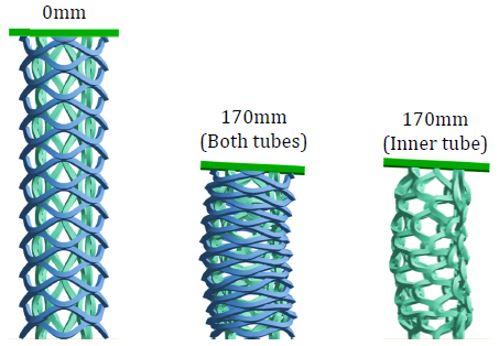
Analyzing the collapse of the concentric tubes (Figures 9 and 10), it was observed that the wall of the inner tube (α = 90°) moved outwards, until getting in contact with the wall of the outer tube (α = 0°). As both tubes collapsed, the wall of the outer tube limits the radial displacement of the wall in the inner, restricting its mode of collapse inducing additional plastic deformation in the inner.
Additionally, it is worth noticing that the concentric tube H23A exhibited a more controlled collapse mode than tubes H23 and H27A. As indicated in Table 1, the length of the axes in mesh H23A are smaller than for the other two tubes, hence the outer tube is more effective controlling the outward displacement of the inner. On the contrary, for tubes H23 and H27A the cells are larger allowing more interaction between the walls of the tubes, consequently the deformation is more irregular.
4 CONCLUSIONS
A numerical study on the axial crushing of expanded metal tubes subjected to impact load was conducted herein. During the axial collapse of concentric tubes 90 - 0, the inner tube with α = 90⁰ begins to fail by global buckling moving towards the wall of the outer tube with α = 0⁰, therefore the inner tube is restrained and forced to deform to fit a reduced volume. In this manner, the amount of energy absorbed by plastic deformation increases and the failure mode to collapse the tube is controlled, thus maintaining a constant collapse strength, which is a desirable property in energy absorption devices. Furthermore, a better cell aspect ratio enhances the energy absorption capacity for similar thickness, as can be seen in the mean force results. Finally, the impact speed has a small effect in the mean load due to the hardening effect of the strain velocity, but the crushing length is increased to absorb the total kinetic energy.
References
- Abdelaal, A.H.A., Tarlochan, F., (2015). Numerical simulation of a novel expanded metal tubular structure for crashworthiness application. In IOP Conference Series: Materials Science and Engineering Vol. 100, No. 1, p. 012063. IOP Publishing. (http://iopscience.iop.org/article/10.1088/1757-899X/100/1/012063/meta)
» http://iopscience.iop.org/article/10.1088/1757-899X/100/1/012063/meta - Abramowicz, W., Jones, N., (1984). Dynamic axial crushing of square tubes. International Journal of Impact Engineering 2(2):179-208.
- ANSYS AUTODYN User’s Manual Theorеtical manual, ANSYS Inc. Southpoint, 275 Technology Drive, Canonsburg, PA, USA, 2010.
- ANSYS, Inc, ANSYS Release 12.0 Elements Reference, USA. 2009.
- Baroutaji, A., Gilchrist, M.D., Olabi, A.G., (2016). Quasi-static, impact and energy absorption of internally nested tubes subjected to lateral loading. Thin-Walled Structures 98B:337-350.
- Baroutaji, A., Morris, E., Olabi, A.G., (2014). Quasi-static response and multi-objective crashworthiness optimization of oblong tube under lateral loading. Thin-Walled Structures 82:262-77.
- Borges, H., (2015). Caracterización de la fuerza de colapso en tubos de metal expandido sometidos a cargas de impacto, Master Thesis, Coordinación de Postgrado en Ingeniería Mecánica, Universidad Simón Bolívar, Caracas, Venezuela [In Spanish]. http://www.bib.usb.ve/tesis/000168137.pdf
» http://www.bib.usb.ve/tesis/000168137.pdf - Borges, H., Martínez, G., Graciano, C., (2016). Impact response of expanded metal tubes: A numerical investigation. Thin-Walled Structures 105:71-80.
- Cowper G.R, Symonds P.S., (1957). Strain-hardening and strain-rate effects in the impact loading of cantilever beams, Brown University Division of Applied Mathematics, Providence, Rhode Island, USA.
- Expanded Metal Manufacturers Association (EMMA). Division of the National Association of Architectural Metal Manufacturers (NAAM) “EMMA 557-12: Standards for expanded metal”, 2012.
- Graciano, C., Martínez, G., Saavedra, E., (2016). Effect of elastoplastic behavior on the impact response of expanded metal tubes. DYNA, 83(198):102-109.
- Graciano, C., Martínez, G., Smith, D., (2009). Experimental investigation on the axial collapse of expanded metal tubes. Thin-Walled Structures 47:953-61.
- Haghi, M., Shahsavari, H., Akbarshahi, H., Shakeri, M., (2013). Bitubular square tubes with different arrangements under quasi-static axial compression loading. Materials and Design 51:1095-103.
- Hatami, H., Nouri, M.D. (2015b). Experimental and numerical investigation of lattice-walled cylindrical shell under low axial impact velocities. Latin American Journal of Solids and Structures, 12(10):1950-1971.
- Jones, N., Abramowicz, W., (1985). Static and dynamic axial crushing of circular and square tubes. Metal Form Impact Mechanics 10:225-47.
- Martínez, G., Graciano, C., Teixeira, P., (2013). Energy absorption of axially crushed expanded metal tubes. Thin-Walled Structures 71:134-46.
- Morris, E., Olabi, A.G., Hashmi, M.S.J., (2006). Analysis of nested tube type energy absorbers with different indenters and exterior constraints. Thin-Walled Structures 44:872-85.
- Morris, E., Olabi, A.G., Hashmi, M.S.J., (2007). Lateral crushing of circular and non-circular tube systems under quasi-static conditions. Journal of Materials Processing Technology 191:132-35.
- Nagel G.M, Thambiratnam D.P., (2004). A numerical study on the impact response and energy absorption of tapered thin-walled tubes. International Journal of Mechanical Sciences 46:201-16.
- Nia, A.A., Chahardoli, S., (2016a). Mechanical behavior of nested multi-tubular structures under quasi-static axial load. Thin-Walled Structures 106:376-389.
- Nia, A.A., Chahardoli, S., (2016b). Optimizing the layout of nested three-tube structures in quasi-static axial collapse. Thin-Walled Structures 107:169-181.
- Nia, A.A., Khodabakhsh, H., (2015). The effect of radial distance of concentric thin-walled tubes on their energy absorption capability under axial dynamic and quasi-static loading, Thin-Walled Structures 93:188-197.
- Niknejad, A., Orojloo, P.H., (2016). A novel nested system of tubes with special cross-section as the energy absorber. Thin-Walled Structures 100:113-123.
- Nouri, M.D., Hatami, H., Jahromi, A.G., (2015a). Experimental and numerical investigation of expanded metal tube absorber under axial impact loading. Structural Engineering and Mechanics, 54(6):1245-1266.
- Sánchez, R., (2005). Determinación de las Propiedades Mecánicas de Láminas de Metal Expandido, Master Thesis, Coordinación de Postgrado en Ingeniería Mecánica, Universidad Simón Bolívar, Caracas, Venezuela [In Spanish].
- Smith D, Graciano C, Martínez G, Texeira P., (2014a). Axial crushing of flattened expanded metal tubes. Thin-Walled Structures 85:42-49.
- Smith, D., Graciano, C., Martínez, G., (2009). Recent patents on expanded metal. Recent Patents on Materials Science 2(3);209-25.
- Smith, D., Graciano, C., Martínez, G., (2014b). Quasi-static axial compression of concentric expanded metal tubes. Thin-Walled Structures 84:170-176.
- Zhang, Y., Sun, G., Li, G., Luo, Z., Li, Q., (2012). Optimization of foam-filled bitubal structures for crashworthiness criteria. Materials and Design 38:99-109.
- Zhang, Z., Liu, S., Tang, Z., (2010). Crashworthiness investigation of kagome honeycomb sandwich cylindrical column under axial crushing loads. Thin-Walled Structures 48(1):9-18.
Publication Dates
-
Publication in this collection
June 2017
History
-
Received
09 Jan 2017 -
Reviewed
16 Mar 2017 -
Accepted
19 Mar 2017


