
 Comparative Case-Study Analysis of Lightweight and Conventional Concrete in Structural Elements of a Multi-Story Building
Abstract
This study evaluates the structural implications of adopting lightweight concrete (LC) in multistory buildings, with emphasis on columns – a configuration seldom examined. Three models of the same fourstory building – (i) all conventional concrete (CC), (ii) LC in slabs and beams (CLC), and (iii) LC in slabs, beams, and columns (LC) – were analyzed in AltoQi Eberick V10. Verifications followed NBR 6118 (ABNT 2023a); where NBR 6118 does not prescribe LC material properties, ACI 318-19 (ACI 2019) was used for the elastic modulus and EN 199211 (CEN 2004) for the densitybased tensile adjustment. Results show foundation loads decreased by up to 12.8% and total steel consumption by up to 13.7% with LC, while lateral displacements remained within code limits. Applying LC in columns increased the global instability index to γz = 1.10 yet retained a nonsway classification. The column case clarifies the tradeoff between weight reduction and increased deformability and provides codeanchored guidance for safe adoption in Brazilian practice. Overall, the findings indicate that LC is structurally viable and materially efficient for multistory buildings under NBR-based design, and highlight priorities for detailing and stiffness control when columns are also cast with LC.
Key words
Building Structures; Global Stability; Lightweight Concrete; Reinforced Concrete Structures; Structural Analysis
INTRODUCTION
Concrete is, indisputably, the most widely used material in modern civil engineering, playing a fundamental role across a wide range of construction typologies—from small residential buildings and road pavements to large-scale infrastructure projects such as skyscrapers, dams, and offshore platforms (Diaferio & Varona 2024, Du & Jin 2021). Its widespread adoption over the decades is attributed to the abundance of raw materials, competitive cost, and versatility in molding various geometries (Li et al. 2022).
Despite its widely recognized advantages, conventional concrete has notable limitations, particularly its low tensile strength and high density, which significantly increase the self-weight of structures (Guo 2014, Neville & Cremonini 2016). These characteristics have driven, over the years, the development of technologies aimed at improving structural performance and construction efficiency through the creation of so-called special concretes.
Among these technological alternatives, lightweight concrete stands out as a strategic solution for reducing permanent loads in structures, contributing to the relief of internal stresses and optimizing material consumption, especially in multi-story buildings and precast systems. With a density below 2000 kg/m³, its lightness is achieved through the incorporation of natural or artificial lightweight aggregates, the addition of foaming agents, or the combination of techniques that promote a more porous matrix (Lu 2023, Newman & Owens 2003, Sahoo et al. 2022, Thienel et al. 2020).
Lightweight concrete offers additional advantages that go beyond simply reducing self-weight. In addition to enabling more economical design of elements such as beams, slabs, and foundations, its use facilitates logistical gains by easing the transportation and assembly of precast components. Furthermore, its physical and mechanical properties can lead to improved thermal and acoustic performance in buildings –features increasingly valued in today’s construction industry (Dabbaghi & Ogunsanya 2024, Newman & Owens 2003).
From a technical perspective, the use of lightweight concrete in structural elements requires careful evaluation of parameters such as compressive strength, modulus of elasticity, and creep, as its behavior differs significantly from that of conventional concrete. Replacing traditional aggregates with lightweight ones, such as expanded clay, may lead to reduced stiffness and increased deformability, which directly affects displacements and the overall stability of the structure (Asif & Wayal 2021). Nonetheless, studies have shown that when properly specified, lightweight concrete can fully meet code requirements, ensuring satisfactory structural performance (Badogiannis et al. 2021, Lu 2023, Wei et al. 2022).
Lightweight concrete (LC) for structural use typically exhibits oven-dry densities in the range of 1.6-1.85 t/m³ (NBR NM 35) (ABNT 1995, Newman & Owens 2003). For fck ≈ 30 MPa, density-based relations (ACI 318-19) (ACI 2019) lead to secant moduli on the order of 17-22 GPa. Compared with normal-weight concrete, LC generally shows a lower tensile strength – reflected by the density reduction factors in EN 1992-1-1 (CEN 2004) – and higher creep and drying shrinkage, which reinforces the need for careful checks of serviceability and global stability, as emphasized in this study.
In Brazil, the use of structural lightweight concrete remains limited, being more commonly employed in non-load-bearing systems such as partition walls and precast masonry units. However, recent studies conducted by authors such as Rossignolo (2021) and Rodrigues et al. (2022) have demonstrated the feasibility of using lightweight concrete made with locally produced expanded clay in load-bearing structural elements, showing a significant reduction in steel consumption and improved construction efficiency.
Despite these advancements, there is still a lack of studies that comprehensively analyze the global behavior of buildings when different combinations of lightweight and conventional concrete are applied to key elements such as beams, slabs, and especially columns. The analysis of column performance is particularly relevant due to their essential role in the global stiffness of the structure and in resisting horizontal displacements.
Previous research conducted by Islam et al. (2024), Vives et al. (2021), Abd & Ghalib (2018) and Selwyn Babu & Rex (2019) has shown that the partial replacement of conventional concrete with lightweight concrete in beams and slabs can lead to reduced steel consumption and lower loads on foundations, albeit with an increase in vertical and horizontal displacements. However, these studies did not delve into the impact of applying lightweight concrete in columns – a factor that could significantly affect the global stability and behavior of the structure under horizontal actions.
This study quantifies, under controlled modeling conditions – identical geometry and actions – the effect of lightweight concrete (LC) on the global behavior of a multi-story building by comparing three configurations: (i) all elements in conventional concrete (CC); (ii) LC applied only to slabs and beams; and (iii) LC applied to slabs, beams, and columns. Beyond a direct comparison of critical structural parameters – foundation loads, total reinforcement, lateral displacements, and global stability via γz – the work explicitly evaluates the use of LC in columns, a topic rarely addressed in the literature, while preserving comparability by holding geometry and actions constant.
All verifications follow NBR 6118 (ABNT 2023a); only where NBR 6118 does not prescribe specific LC material properties are ACI 318-19 (ACI 2019) used for the elastic modulus and EN 1992-1-1 (CEN 2004) for the density-based tensile adjustment. The analysis yields numerical evidence and a code-anchored design message: it clarifies the trade-off between weight/reaction reduction and increased deformability, indicates when LC can be adopted without changing member sizes, and identifies where targeted measures for global stiffness control (with γz remaining in the non-sway range) become advisable. In this context, the work addresses gaps arising from the limited Brazilian guidance for LC structural design and provides support for its consolidation as a viable and safe alternative in multi-story buildings.
MATERIALS AND METHODS
Materials
Two types of structural concrete with a characteristic compressive strength of 30 MPa were adopted: a conventional concrete and a structural lightweight concrete using expanded clay as coarse aggregate. Both were used in the comparative study. A consolidated summary of the adopted parameters for the three configurations (CC, CLC, and LC) is provided in Table II. The following subsections detail the governing code provisions and calculations.
Density class and corresponding density of lightweight aggregate concrete according to EN 206-1 (CEN 2004).
Conventional concrete
For the modeling of the conventional structure, parameters corresponding to a concrete with a characteristic compressive strength of 30 MPa were adopted, in accordance with NBR 6118 (ABNT 2023a), the Brazilian standard for structural design in reinforced concrete. This standard aligns directly with ACI 318-19 (ACI 2019) in the United States and EN 1992-1-1 (CEN 2004) in Europe, both of which are widely used in international design practice.
The conventional concrete was defined using Portland Cement with Additions (CP-II), in accordance with NBR 16697 (ABNT 2018), which presents suitable characteristics for use in reinforced concrete structures exposed to Environmental Aggressiveness Class II (moderate). This cement exhibits behavior similar to C595/C595M-23 (ASTM 2023b) Type IP (USA) and to CEM II/A-P or CEM II/B-P, as specified by the European standard EN 197-1 (CEN 2011), both containing pozzolanic additions. The aggregates used were natural fine aggregates and coarse granite aggregates. The conventional concrete was characterized by a dry density of 2400 kg/m³ and unit weight of 25 kN/m³ for reinforced concrete, as recommended by NBR 6118 (ABNT 2023a).
Determination of the modulus of elasticity for conventional concrete
The secant modulus of elasticity for conventional concrete was determined in accordance with the specifications of NBR 6118 (ABNT 2023a). The value of Ecs results from the multiplication of the initial modulus of elasticity (Eci) by the correction factor αi, the latter being a function of the characteristic compressive strength (fck), as shown in Equation 01:
The initial modulus of elasticity was calculated using Equation 02:
Where αₑ e represents the coarse aggregate type factor. This factor depends on the nature of the coarse aggregates used in the concrete mix. According to NBR 6118 (ABNT 2023a), the values are: 1.2 for basalt and diabase; 1.0 for granite and gneiss; 0.9 for limestone; and 0.7 for sandstone. In this study, a value of 1.0 was adopted for granite aggregate. A characteristic compressive strength fck of 30 MPa was considered, resulting in an initial modulus of elasticity of 30,038.8 MPa.
The correction factor αi was obtained using the normative Equation 03.
Accordingly, a value of 0.875 was calculated for the correction factor, resulting in a secant modulus of elasticity of 26,288.9 MPa. This value was adopted in the structural model using conventional concrete.
Tensile strength of conventional concrete
The average tensile strength of conventional concrete was calculated according to NBR 6118 (ABNT 2023a), applicable for concretes with fck ≤ 50 MPa. Considering an fck of 30 MPa, the value obtained was (Equation 04):
For design purposes, the design tensile strength was obtained by dividing the mean value by 1.4, as prescribed by the Brazilian code for normal design actions. Thus, a value of 2.06 MPa was adopted in the structural modeling performed using the software. Tensile strength is used exclusively for serviceability checks – particularly for deflection evaluation – through the software’s internal models in accordance with this standard.
Structural lightweight concrete
The structural lightweight concrete used in this study was composed of Portland cement, conventional fine aggregates, and expanded clay type 1506 as coarse aggregate. This application is regulated by NBR NM 35 (ABNT 1995), the Brazilian standard for lightweight aggregates in structural concrete, which corresponds C330/C330M-23 (ASTM 2023a), widely used for the same purpose internationally.
According to NBR NM 35 (ABNT 1995), a dry density of 1750 kg/m³ was adopted, consistent with the established limits for lightweight concrete with a minimum strength of 28 MPa and a maximum allowable density of 1840 kg/m³. This value was selected based on the typical properties of expanded clay commercially available in the national market.
For structural analysis, the unit weigth of the reinforced lightweight concrete was considered to be 18.5 kN/m³, as recommended by NBR 6118 (ABNT 2023a), which suggests adding 1 kN/m³ to the dry concrete density to account for reinforcement weight.
In addition, High Early Strength Portland Cement (CPV-ARI) was used, equivalent to C150/C150M-22 (ASTM 2022b) Type III and EN 197-1 (CEN 2011) CEM I 52.5 R. This choice was based on the need for better control of shrinkage (Maulidyah et al. 2024, Szydłowski & Łabuzek 2021) and creep (Daneti et al. 2024), which are typical concerns in lightweight concrete due to the lower stiffness of expanded aggregates. The use of CPV-ARI ensures faster strength gain, helping to mitigate differential deformation in slender structural elements and reducing formwork removal time—an important factor in lightweight concrete and precast structures.
The lightweight concrete was specified with a characteristic compressive strength of 30 MPa, which is sufficient to meet the requirements of environmental exposure class II (moderate), according to NBR 6118 (ABNT 2023a), and complies with the minimum standards defined in equivalent codes such as EN 1992-1-1 (CEN 2004).
Determination of the modulus of elasticity for lightweight concrete
The secant modulus of elasticity for lightweight concrete was determined using the ACI 318-19 (ACI 2019) equation, which is widely adopted internationally for lightweight concretes with densities ranging from 1440 kg/m³ to 2480 kg/m³. Because NBR 6118 (ABNT 2023a) does not provide a specific prescription for estimating the modulus of lightweight concrete as a function of density, the ACI 318-19 (ACI 2019) expression was adopted, which directly relates density and compressive strength of LC to its global stiffness (Equation 05).
Where Elc is the secant modulus of elasticity (MPa), γ is the density of the lightweight concrete (kg/m³), and fck is the characteristic compressive strength (MPa). This method allows for a more realistic estimation of the stiffness of lightweight concretes, whose deformability tends to be higher due to the lower density of expanded aggregates. Substituting the values adopted in this study (γ = 1750 kg/m³ e fck = 30 MPa), the resulting Elc is 19.405 MPa. This value was used in the numerical modeling of the building under the different simulated structural configurations. Tensile strength is employed only in serviceability checks (deflections), with a density-based adjustment per EN 1992-1-1 (CEN 2004), as implemented by the software.
Tensile strength of lightweight concrete
The tensile strength of lightweight concrete was determined in accordance with the recommendations of EN 1992-1-1 (CEN 2004), which applies a density-based reduction. EC2 was used because NBR 6118 (ABNT 2023a) does not provide a density-dependent relation for LC tensile strength. The standard suggests that the mean tensile strength of structural lightweight concrete (flct,m ) should be adjusted from the mean tensile strength of conventional concrete (fct,m ) using a reduction factor (η1), as shown in Equation 06:
The factor η1 is defined by Equation 07:
Where ρ is the upper limit of the dry density for the respective density class, as specified in Table I of EN 206-1 (CEN 2004).
Thus, considering that the lightweight concrete used in this study has an actual density of 1750 kg/m³ and falls within a class with a maximum density of 1800 kg/m³, a value of ρ = 1800 kg/m³ was used in the calculation of η1, resulting in a factor of 0.891. The value of fct,m for conventional concrete was adopted according to NBR 6118 (ABNT 2023a), which recommends 2.90 MPa for concrete with a characteristic compressive strength of 30 MPa. Therefore, the mean tensile strength of the lightweight concrete used in this study was 0.891 ⋅ 2.90 = 2.58 MPa. This value was then used to calculate the design tensile strength, considering a partial safety factor of 1.4 for standard design loads. Accordingly, the design tensile strength fctd was 1.84 MPa, which was used in the structural models for the lightweight concrete.
Table II presents a summary of the concrete property values used in the structural design.
Reinforcement
The reinforcement used in the structural modeling was defined according to the specifications of NBR 7480 (ABNT 2020), the Brazilian standard governing the characteristics of steel bars and wires for reinforced concrete. This standard corresponds to A615/A615M-22 (ASTM 2022a) and EN 10080 (CEN 2005), which regulate the properties of steel used in concrete structures.
The following were considered:
-
CA-50 steel (fyk = 500 MPa) for the longitudinal reinforcement of beams, columns, slabs, and stairs;
-
CA-60 steel (fyk = 600 MPa) for stirrups, transverse reinforcement, and the top mesh of slabs.
CA-50 steel exhibits behavior equivalent to 615 Grade 60 (A615/A615M-22) (ASTM 2022a), while CA-60 corresponds to Grade 75 of the same American standard and to B500B or B500C steel in EN 10080 (CEN 2005). The selection of CA-50 and CA-60 steels follows standard practice for designing reinforced concrete structures in Brazil and was implemented for both the conventional and lightweight concrete structures. Reinforcement connections followed the conventional detailing prescribed by NBR 6118 (ABNT 2023a), including hooks, bends, and splices, depending on the type of stress and structural element.
The following modeling steps were identical for all three configurations, ensuring that any differences observed in the results arise solely from the adopted concrete type.
Methods
The experimental program involved the analysis of the architectural design and the characterization of materials, including the definition of the mechanical properties of both lightweight and conventional concrete, such as specific gravity, secant modulus of elasticity, compressive strength, and tensile strength. Subsequently, the structural configurations and the vertical and horizontal loads applied were defined. The structural model was created and processed using AltoQi Eberick software (AltoQi Tecnologia Ltda. 2020), following the relevant code requirements. After processing, aspects such as global stability, horizontal displacements, beam and slab deformations, foundation forces, shear forces in beams, and material quantities were evaluated, culminating in the analysis of the results and the study’s conclusions. The experimental plan developed to achieve the proposed objectives is described in the activity flowchart shown in Figure 1.

Architectural context
The study considered a residential building located in the state of Paraíba, Brazil, comprising four levels: a ground floor, three typical floors, and a roof. Each typical floor contains two apartments (total floor area: 143.39 m²), replicating the same layout as the ground floor in terms of circulation areas and stairways. The complete architectural floor plans and sections are presented in Supplementary Material - Figures S1-S4, and were used solely as the basis for developing the structural model.
Structural model and studied structures
The building was modeled as a three-dimensional reinforced-concrete frame, with layout and member dimensions consistent with the architectural scheme and the provisions of NBR 6118 (ABNT 2023a). Numerical analyses were performed using AltoQi Eberick V10 (AltoQi Tecnologia Ltda. 2020). The architectural form plans used in the model are provided in the Supplementary Material (Figures S1-S4), and the corresponding structural drawings and a representative structural section are provided in the Supplementary Material (Figures S5-S9), outlining the arrangement of slabs, beams, and columns adopted in the study.
The building behaves as a three-dimensional reinforced-concrete frame system. Gravity loads are carried by slabs, beams, and columns along the vertical load path. Horizontal loads are resisted by the bending stiffness of the interconnected frames in both principal directions. The slabs act as rigid diaphragms that collect wind actions and distribute them to the frames. Column bases were modeled as fixed supports. No shear walls were included, so the global lateral stiffness derives from the frame action.
For the comparative assessment, three structural configurations with identical member dimensions and identical actions were considered to ensure model-to-model comparability: CC (all elements—slabs, beams, columns, and the tank—in conventional concrete), CLC (slabs, beams, and tank in lightweight concrete; columns in conventional concrete), and LC (all elements in lightweight concrete). These configurations are hereafter referred to as CC, CLC, and LC.
Preliminary sizing established the initial dimensions of slabs, beams, and columns and served as the basis for the structural model. This step followed practice-oriented recommendations from the literature (Ambrose & Tripeny 2007, Botelho 2016, Ochshorn 2020) and the provisions of NBR 6118 (ABNT 2023a), aiming to balance constructability and safety. Solid slabs were set to 100 mm thickness; beams were assigned 14 cm width (matching masonry thickness) and 30 cm depth—locally increased to 40 cm where additional stiffness was required; and columns adopted cross-sections of 14×30 cm, 15×30 cm, and 18×40 cm according to local stiffness and loading demands. Tank-support beams at the roof level were detailed with a minimum thickness of 15 cm and depth corresponding to the difference between the tank bottom and rim elevations.
For columns, the influence-area method (Botelho 2016) was employed, relating the design axial load to the tributary area in plan, as expressed in Equation 08:
A is the cross-sectional area of the column, Nd is the design axial load, fcd is the design compressive strength of the concrete, ρ is the longitudinal reinforcement ratio, and σs is the stress in the reinforcement corresponding to a strain of 0.2%. However, the analysis resulted in minimum cross-sections of 14 cm × 30 cm, which were adjusted to 15 cm × 30 cm and 18 cm × 40 cm at specific locations in the structure, according to local stiffness and loading requirements. All adopted dimensions comply with the minimum limits of NBR 6118 (ABNT 2023a).
Global stability
Given the frame-based lateral system described above, global stability was verified in accordance with NBR 6118 (ABNT 2023a) using the γz index, computed from linear first-order analyses in the X and Y directions. The coefficient relates global second-order effects to first-order actions through Equation 09:
Where ∆Mtot,d is the sum of vertical forces times their horizontal displacements (global second-order moments) and M1,tot,d is the sum of first-order overturning moments. According to NBR 6118, frames with γz ≤ 1.10 are classified as non-sway, and global second-order effects are deemed satisfied by the code procedure embedded in the software. The γz values reported here were obtained automatically by AltoQi Eberick for each model and direction.
Durability
The environmental exposure class was defined as II (moderate), in accordance with the criteria established by NBR 6118 (ABNT 2023a). Minimum cover values of 3 cm were adopted for beams, columns, and foundations, and 2.5 cm for slabs. Crack-width limits were 0.2 mm for members in contact with soil, 0.1 mm for members exposed to water, and 0.3 mm for other elements, as specified in Table 13.4 of NBR 6118 (ABNT 2023a). The maximum aggregate size was limited to 19 mm, as required by the code.
Loads
Design actions followed NBR 6120 (ABNT 2019) for vertical loads, NBR 6123 (ABNT 2023b) for wind, and NBR 8681 (ABNT 2003) for combinations at the ULS and SLS. Permanent actions included self-weight with unit weights of 25 kN/m³ (reinforced conventional concrete) and 18.5 kN/m³ (reinforced lightweight concrete), masonry in hollow clay bricks (13 kN/m³), and plaster (19 kN/m³). Floor finishes were taken as 1.0 kN/m² on interior slabs and 0.8 kN/m² on stairs and roof, plus 0.7 kN/m² for the roof covering in designated areas. Live loads were 1.5 kN/m² for bedrooms, living rooms, and kitchens; 2.0 kN/m² for bathrooms and service areas; and 3.0 kN/m² for shared-use corridors. At the roof, an additional 1.0 kN/m² was considered to allow occasional access for inspection and maintenance. Wind actions were determined per NBR 6123 (ABNT 2023b), adopting a basic wind speed of 30 m/s for the state of Paraíba and applying exposure, topography, and shape factors for a rectangular plan with total height below 30 m. For full details, see Table SI.
At the Ultimate Limit State, combinations followed Equation 10:
In this equation, Fd represents the design load, Fgk denotes the characteristic permanent loads, Fqlk is the leading variable load, Fqjk corresponds to the accompanying variable loads, γg and γq are the safety factors applied to permanent and variable actions respectively, and φ0j refers to the combination factors for secondary variable loads. In this study, the adopted values were γg = 1.4, γq = 1.4, and φ0 = 0.7 for both live loads and wind actions. For the Serviceability Limit State, the frequent and quasi-permanent combinations followed Equations 11 and 12:
In these combinations, the factor φ1 was taken as 0.5 for the predominant live load, while φ2 was assumed to be zero for accompanying variable actions under this condition. All load combinations were implemented in the structural analysis software in accordance with the aforementioned standards.
RESULTS AND DISCUSSION
Horizontal displacements
The horizontal displacements of the structures were evaluated considering wind action in two principal directions: parallel and perpendicular to the longest dimension of the building’s floor plan. The analyses were conducted for the three structural configurations modeled: structure with conventional concrete (CC), structure with slabs and beams in lightweight concrete and columns in conventional concrete (CLC), and structure entirely in lightweight concrete (LC).
The floor-by-floor absolute displacements and the interstory drifts for each model and direction are reported in Tables III-V.
When the wind acted parallel to the building’s longest dimension (X-axis), the maximum horizontal displacements recorded were 0.10 cm for the CC structure, 0.12 cm for the CLC structure, and 0.14 cm for the LC structure. In the perpendicular direction (Y-axis), the displacements were higher, with maximum values of 0.30 cm, 0.34 cm, and 0.41 cm, respectively, for the CC, CLC, and LC structures. Compared to the CC configuration, the CLC structure showed increases of 20% in the X-axis and 13.3% in the Y-axis in terms of maximum horizontal displacement. The LC structure exhibited increases of 40% and 36.7% in the same directions, respectively.
All horizontal displacements remained below the limit of H/1700, which, for the height of the analyzed building (H = 16.50 m), corresponds to 0.97 cm, as required by NBR 6118 (ABNT 2023a).
The observed behavior highlights the direct influence of lightweight concrete on the global stiffness of the structure. The lower stiffness of lightweight concrete, associated with its reduced modulus of elasticity compared to conventional concrete, resulted in greater displacements in the CLC and LC structures. It is worth noting that the increase in displacements in the LC structure was more pronounced due to the application of lightweight concrete in the columns as well, which are critical elements for the global stability of the structural system. This behavior is consistent with findings from other researchers, such as Oushabi et al. (2017), Rodacka et al. (2023) and Jahami et al. (2024), who also reported increased vertical and horizontal deformations in structural elements when using lightweight concrete, especially due to its lower modulus of elasticity.
Tables III-V present the horizontal displacements and the interstory drift (defined as the difference between the displacement of a floor and that of the immediately lower floor) for each configuration and wind direction.
The results obtained for interstory drift in all configurations remained below the code limits established by NBR 6118 (ABNT 2023a) for each of the floors analyzed. According to the standard, interstory drift must be less than Hi/850, where Hi is the story height between two consecutive levels. Thus, for floors with Hi = 280 cm, the limit is 0.33 cm; for the level with Hi = 127 cm, the limit is 0.15 cm; and for the top of the water tank, with Hi = 122.5 cm, the limit is 0.14 cm.
Analyzing the maximum interstory drifts for a story height of 280 cm, the value was 12.5% higher in the CLC structure compared to the CC structure. Similarly, the LC structure also exhibited a 12.5% increase.
The increases observed for CLC/LC are governed primarily by the lower elastic modulus of LC rather than by load changes. When columns are also cast in LC, story-sidesway effects become more pronounced, yet all code limits are satisfied. From a design standpoint, global stiffness control should be prioritized when extending LC to columns (e.g., deeper beams, more effective end fixity, or enhanced diaphragm stiffness where warranted).
Global stability
Global stability was assessed by the γz index in accordance with NBR 6118 (ABNT 2023a). Figure 2 reports the γz coefficient values, considering wind acting parallel to the building’s longest dimension in plan (X-axis) and perpendicular to it (Y-axis). It also shows the calculated first-order overturning moment (M1,tot,d) and the global second-order moment (∆Mtot,d).

All models satisfied γz ≤ 1.10 and are therefore classified as non-sway per NBR 6118 (ABNT 2023a), so global second-order effects may be neglected. The CC and CLC configurations yielded identical γz values in both directions – 1.09 (X) and 1.08 (Y) – indicating that using LC only in slabs and beams has minimal impact on global stability when columns remain conventional. In the LC configuration, γz increased to 1.10 (X) and 1.09 (Y), reflecting larger second-order effects driven by higher displacements due to the lower elastic modulus of LC; even so, the non-sway classification is retained.
For both X and Y directions, Figure 2 also reports the first-order overturning moment (M1,tot,d) and the global second-order moment (ΔMtot,d). The overturning moment under wind in Y is 2.26 times that in X. The adopted stiffness strategy along the axis with the larger M1,tot,d (Y) – by enlarging beam and column dimensions as described in the structural configurations – reduced the ratio ΔMtot,d/M1,tot,d, which is consistent with γz(Y) being slightly lower than γz(X) in CC/CLC. In LC, the lower elastic modulus of LC increased lateral displacements and thus ΔMtot,d, explaining the modest rise in γz, while the frame remained non-sway (γz ≤ 1.10).
Even with 2.26 times the overturning moment in Y compared to X, global stability remained satisfactory (γz = 1.08–1.10). The directional difference reflects a balance between action level (M1,tot,d) and deformation-driven second-order effects (ΔMtot,d): stiffening along Y effectively lowers ΔM/M1, whereas extending LC to columns shifts the governing criterion to global stiffness control. From a design standpoint, maintaining non-sway margins with LC columns is best achieved through targeted measures – e.g., deeper beams, more effective end fixity, or diaphragm stiffening—without forfeiting the weight-reduction benefits.
Slab deflection
The analysis of total displacements in the slabs considered the results for the third floor, where the largest deformations were observed among the structures. Figure 3 presents the total deflections obtained for the CC, CLC, and LC structures.

Analyzing the results, it is observed that the use of lightweight concrete led to an increase in slab deflections, with LC and CLC structures presenting higher values compared to the CC structure. However, all recorded displacements were lower than the L/250 limit established by NBR 6118 (ABNT 2023a), ensuring compliance with the visual acceptability criteria for slab deformations.
Among the configurations, the structure with full lightweight concrete application (LC) exhibited the highest total slab deflections, followed by the CLC structure. The increase in total displacements for the LC structure ranged from 0% to 34.6% compared to the CC structure, while the increase for the CLC structure ranged from 0% to 23.1%.
These results reinforce that the reduction in specific weight due to the use of lightweight concrete leads to smaller vertical loads but also decreases the flexural stiffness of the slabs, resulting in greater vertical displacements. The increase in total deflection in CLC/LC is primarily stiffness-driven (due to the lower elastic modulus of lightweight concrete); all values remain within the L/250 limit. For longer spans or more deformation-sensitive applications, targeted stiffness measures—such as increased effective depth, compression reinforcement, or ribbed solutions—may be adopted while preserving the weight-reduction benefits.
Internal forces in beams
To analyze the internal forces in the beams, the results for the third floor were considered again, given the greater deformations observed.
Figure 4 shows the maximum positive and negative bending moments obtained for the beams, while Figure 5 presents the maximum shear forces.


From the bending moment analysis (Figure 4), it is observed that the CLC and LC structures presented lower maximum moments compared to the CC structure for almost all beams. This reduction is associated with the lower permanent loads resulting from the use of lightweight concrete.
However, for certain beams, the LC structure showed an increase in internal moments compared to the CLC structure. The effect is consistent with the lower global stiffness of LC and the associated redistribution under lateral actions. The beams V11, V16, and V20 exhibited the highest positive moments, while V2, V10, and V16 recorded the highest negative moments. The reduction in positive moments for the CLC structure compared to the CC structure was 13.1%, and for negative moments, the reduction was 10.8%.
Regarding shear forces (Figure 5), the same trend was observed: the structures with lightweight concrete showed lower maximum shear forces compared to the CC structure. The LC structure exhibited slightly higher shear forces than the CLC structure, which can also be explained by the reduced stiffness and greater sensitivity to lateral loads. The greatest reductions in shear forces were found in beams V11, V16, and V20, with an average reduction of 11.4% when using lightweight concrete in slabs and beams. This reduction in shear demands directly benefits the structural design, allowing for a reduction in the required amount of transverse reinforcement in beams, contributing to material optimization.
Weight reduction with CL lowers bending and shear demands on most beams, while the lower global stiffness of CL explains localized increases (CL versus CLC) through internal-force redistribution under lateral actions. Overall, the net effect favors design economy—reflected in the ~11–13% reductions—while highlighting that targeted stiffness checks are advisable where local peaks occur.
Beam deflection
The total deflections of the beams on the third floor were also analyzed. For a more accurate assessment, the greatest deflection was considered for beams with more than one span. Figure 6 presents the total deflections for the CC, CLC, and LC structures.

The total deflections of beams made with lightweight concrete were always equal to or greater than those of the CC structure. However, all beams exhibited displacements below L/250, remaining within the visual acceptability limit for structural elements established by NBR 6118 (ABNT 2023a). The LC beams presented the highest deflections due to the reduced stiffness of the supporting columns made with lightweight concrete, which increased overall deformability. The total deflections in LC beams rose by 10% to 34.8% compared to CC, while in the CLC structure, the increase ranged from 0% to 18.75%.
A direct relationship was observed between internal forces and maximum beam displacements. To examine it, quadratic response-surface models (multiple regression) were fitted, relating maximum deflection to shear (V), positive bending (M⁺), and negative bending (M⁻). In each model, V, M⁺, and M⁻ were treated as independent variables and the maximum vertical displacement as the response. To isolate moment effects, two companion surfaces were generated per structure: one with M⁻ = 0 (positive bending only) and another with M⁺ = 0 (negative bending only). A single statistical model was used for each structure; only the nullified moment differed when constructing the companion surfaces. Relative contributions and interactions were evaluated with Pareto charts derived from ANOVA; the dashed reference line marks the adopted significance level, and bars above it denote statistically significant factors or interactions.
Figure 7 presents the analysis related to the fully conventional structure (CC). Upon examination, it is observed that the response surface constructed for the positive bending moments (M⁺) and shear forces (V) reveals a predominant influence of shear on the maximum deflections of the beams in the CC structure. The surface exhibits significant curvature primarily as a function of the shear force, suggesting the presence of nonlinear behavior, which is corroborated by the inclusion of quadratic terms in the adjusted model. The surface corresponding to negative moments (M⁻) and shear forces (V) maintains the same trend, reinforcing the conclusion that, even when different types of bending moments are considered, the shear force remains the most influential variable affecting vertical displacements.
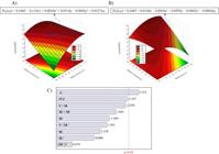
Response surfaces and Pareto chart for the influence of internal forces on beam deflections – CC structure.
This interpretation is reinforced by the analysis of the associated Pareto chart, also presented in Figure 7. According to the chart, the shear force (V) is the factor with the greatest positive effect on displacements, with a normalized coefficient of 2.518, followed by the quadratic term V² and the interaction between shear and negative bending moment (V × M⁻). These results indicate that both the magnitude of the shear force itself and its quadratic variation have a significant impact on beam deformation. The contribution of bending moments, both positive and negative, was considerably lower, with normalized effects well below those associated with shear. It is also observed that the factors related to shear exceed the established significance threshold, confirming their statistically dominant role in the deformational behavior of the beams.
The R² value of 0.784 obtained for the statistical model indicates that approximately 78.4% of the variability in maximum vertical displacements can be explained by the independent variables analyzed (V, M⁺, M⁻), which represents a satisfactory fit for comparative analysis purposes. From a structural perspective, the dominance of shear force in generating deflections in beams composed of conventional concrete reinforces the importance of transverse stiffness and the control of vertical loads in minimizing vertical displacements in traditional structural systems. The relatively smaller contribution of bending moments may be attributed to the high flexural stiffness provided by conventional concrete, which reduces deformations associated with bending moments, even in moderately long spans.
The analysis presented in Figure 8, corresponding to the CLC structure (with slabs and beams made of lightweight concrete and columns made of conventional concrete), shows that the shear force (V) continues to be the most influential variable on the maximum vertical displacements of the beams, with an even greater predominance than in the CC structure. This increased influence of shear can be attributed to the reduction in both the specific mass and the elastic modulus of the lightweight concrete used in the slabs and beams, which lowers the flexural-transverse stiffness of the structural elements.

Response surfaces and Pareto chart for the influence of internal forces on beam deflections – CLC structure.
The pronounced curvature of the response surfaces confirms the importance of quadratic terms in the statistical model, and the analysis of the Pareto chart indicates that, in addition to the direct effects of shear, its interactions with negative bending moments (V × M⁻) also have a significant contribution. This greater interaction highlights that, in the presence of lightweight concrete, the structural system becomes more sensitive to combinations of internal forces rather than to isolated loading effects.
The isolated contributions of positive and negative moments remain relatively low, but their combined effect with shear becomes considerably relevant. This behavior suggests that, for CLC-type structures, design strategies aimed at mitigating displacements should focus not only on controlling shear forces but also on limiting unfavorable interactions between negative bending and transverse forces.
The statistical model fitted for the CLC structure showed a coefficient of determination (R²) of 0.761, indicating that 76.1% of the variability in maximum vertical displacements was explained by the analyzed variables (V, M⁺, and M⁻). This value confirms the good quality of the fit and the model’s ability to adequately represent the observed deformational behavior. Structurally, the use of lightweight concrete only in slabs and beams, while maintaining conventional concrete in the columns, leads to an increase in maximum vertical displacements compared to the fully conventional system, though in a controlled and predictable manner, without significantly altering the global behavior of the building.
In contrast, the analysis in Figure 9, corresponding to the LC structure (with lightweight concrete applied in slabs, beams, and columns), reveals that the shear force (V) remains the primary contributor to maximum beam deflections, followed by the positive bending moment (M⁺), whose influence becomes more pronounced compared to the previous structures (CC and CLC).

Response surfaces and Pareto chart for the influence of internal forces on beam deflections – LC structure.
The response surface demonstrates that nonlinear behavior persists, as evidenced by the prominence of the quadratic shear term (V²) in the Pareto chart. However, unlike the previous analyses, the positive bending moment (M⁺) emerges as a significant contributor, suggesting that the reduced global flexural stiffness—resulting from the use of lightweight concrete in columns, beams, and slabs—renders the structure more susceptible to flexure-induced deformations in addition to transverse actions.
This interpretation is supported by the Pareto chart, where M⁺ appears as the third most significant factor, following only V and V². The prominent presence of interaction terms (V × M⁺, V × M⁻) further reinforces the notion that, in more flexible structural systems, the combination of internal forces tends to amplify deformation effects.
The statistical model fitted for this structure presented a coefficient of determination (R²) of 0.786, indicating that 78.6% of the variability in maximum vertical displacements was explained by the analyzed variables (V, M⁺, and M⁻), also confirming the good agreement of the model with the observed data.
From a practical design perspective, these results suggest that for structures made entirely of lightweight concrete, displacement control strategies should address both the reduction of shear forces and the limitation of positive bending moments. It is advisable to reinforce regions with higher moment demands along the spans of structural elements.
The response surface results for the CC, CLC, and LC structures revealed the predominant role of shear forces in influencing maximum beam deflections. However, it was observed that the increased use of lightweight concrete intensified the influence of positive moments and the interactions between internal forces, particularly in more flexible structures. These findings underscore the importance of simultaneously controlling shear and bending moments in lightweight concrete design to ensure compliance with displacement limits established by structural design codes.
Foundation loads
The foundation loads were obtained by summing the characteristic vertical loads acting on the building’s columns, from the top of the reservoir down to the ground floor, also accounting for wind action in the most unfavorable direction. Figure 10 presents the distribution of vertical loads per column for each of the three structural configurations (a) and the total loads applied to the foundations of each structure (b).
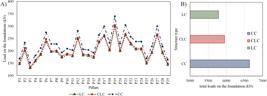
Analyzing Figure 10a, it is evident that, for all columns, the structures using lightweight concrete (CLC and CL) exhibited reduced loads compared to the fully conventional structure (CC). The difference is most pronounced in the CL structure, where the comprehensive use of lightweight concrete in slabs, beams, and columns resulted in the greatest reduction of vertical loads. Notably, column P19, which exhibited the highest loading among all columns, also showed the largest load reduction, with decreases of 35.62 kN in the CLC structure and 40.92 kN in the CL structure compared to the CC structure.
However, not all columns showed proportional reductions. For instance, column P9 experienced the smallest load decrease among the structures, demonstrating that the influence of replacing conventional concrete with lightweight concrete also depends on the column’s location and the distribution of live loads and wind loads, and is not purely a linear effect.
Figure 10b summarizes the total loads acting on the foundations of each structure. The CC structure exhibited a total load of 6639.03 kN, while the CLC structure recorded 5953.08 kN and the CL structure 5787.95 kN, representing reductions of approximately 10.3% and 12.8%, respectively, when compared to the conventional structure.
These results confirm that the use of lightweight concrete leads to a significant reduction in the loads applied to the foundations. This reduction directly affects the design of footings and foundation blocks and can lead to smaller dimensions and potentially avoid the need for more costly solutions, such as deep foundations, depending on the local soil bearing capacity (Sifan et al. 2023, Usman et al. 2025).
Moreover, although the largest load reduction occurs in slabs and beams due to the decrease in self-weight, a cumulative effect was also observed in the columns, albeit to a lesser extent. This behavior highlights the importance of evaluating the structure as a whole when implementing lightweight concrete, maximizing the benefits of structural economy and optimization.
Material quantities
Table VI presents the concrete and formwork consumption for the CC, CLC, and LC structures, based on the detailed quantities obtained from the structural modeling and processing in the design software. It is observed that, since the dimensions of the structural elements (beams, columns, slabs, and stairs) were kept constant across all three configurations, the consumption of concrete and formwork remained equivalent for all structures, with no significant variations.
This behavior confirms that the differences observed in the consumption of structural materials are exclusively associated with variations in the type of concrete used (conventional or lightweight), with no changes in material volumes due to geometric modifications.
Regarding steel consumption, Figure 11 presents a comparative distribution of reinforcement by structural element (a) and the total consumption obtained for each configuration (b).

Comparative analysis of steel consumption by structural element (a) and total steel consumption (b).
An analysis of Figure 11a shows that the beams, columns, slabs, and stairs of the CC structure exhibited higher steel consumption compared to the CLC and LC structures. The greatest difference was observed in the columns, where the use of lightweight concrete led to significant reductions in reinforcement consumption. Slabs and stairs also showed modest reductions, confirming the trend that the reduced self-weight of lightweight concrete positively affects steel demand, particularly in vertical elements.
Figure 11b highlights that the LC structure, with full application of lightweight concrete, recorded the lowest total steel consumption (6069.5 kg), representing a reduction of approximately 13.7% compared to the CC structure (7031.4 kg). The CLC structure, which employed lightweight concrete only in slabs and beams, recorded a total consumption of 6204 kg, equivalent to an 11.8% savings relative to the fully conventional structure.
These results demonstrate that the use of lightweight concrete, in addition to reducing vertical loads, contributes to the optimization of steel usage in the structure, particularly in columns. The decrease in self-weight directly influences the reduction of internal forces, enabling the use of more economical cross-sections and lower reinforcement ratios. Consequently, the adoption of lightweight concrete may represent not only a structurally efficient solution but also an economically viable one, optimizing the total material costs of the project.
CONCLUSIONS
This study analyzed the structural behavior of a reinforced concrete building by comparing three configurations: a conventional concrete structure (CC), a structure with lightweight concrete in beams and slabs (CLC), and a structure entirely using lightweight concrete (LC). The results obtained allowed the following conclusions to be drawn:
-
Serviceability (deflections): Total beam/slab deflections with lightweight concrete were equal to or higher than CC, yet all remained below L/250 (NBR 6118) (ABNT 2023a), meeting visual serviceability limits;
-
Internal forces: Lightweight concrete generally reduced peak bending moments and shear in beams; however, some beams—especially in LC—showed local increases due to lower global stiffness and higher sensitivity to lateral loads;
-
Foundation reactions: Vertical loads on foundations decreased with lightweight concrete: −12.8% (LC) and −10.3% (CLC) vs. CC, enabling more economical foundation design (smaller dimensions or shallower depths);
-
Lateral displacements: Maximum horizontal displacements were higher with lightweight concrete—greatest in LC—confirming the stiffness effect; all within NBR 6118 (ABNT 2023a) limits;
-
Steel consumption: Total steel use decreased significantly: −13.7% (LC) and −11.8% (CLC) vs. CC; savings were most pronounced in column reinforcement due to lower vertical loads;
-
Response surfaces and Pareto: Shear (V) was the primary driver of beam deflection; moment effects (notably M⁺ in LC) gained importance as stiffness decreased, highlighting nonlinearity and stronger V–M interactions in more flexible systems.
The use of lightweight concrete in structural elements was shown to be technically feasible, allowing reductions in vertical loads, steel consumption, and foundation demands without compromising serviceability requirements. Although the lower elastic modulus resulted in slightly higher lateral displacements—particularly in more slender buildings—all measured values remained within the limits established by NBR 6118 (ABNT 2023a), confirming the system’s safety and functionality.
From a design perspective, when the primary goal is to reduce reactions and steel consumption without changing member dimensions, the use of lightweight concrete only in slabs and beams (CLC) proved advantageous, maintaining global stability while achieving clear material savings. In contrast, full application in columns and other elements (LC) requires careful control of global stiffness, with recommended measures such as increasing beam effective depth, improving joint fixity, and optimizing critical column sections to maintain non-pandeability margins (γz ≤ 1.10). In serviceability verification, the simultaneous control of shear and bending effects—particularly in longer spans—proved more effective than isolated approaches. Future studies are encouraged to further assess the economic feasibility of lightweight concrete, considering the balance between material savings and potential needs for additional structural reinforcement.
Acknowledgements
The authors are grateful to the Federal University of Campina Grande, Academic Unit of Environmental Science and Technology for the support of the research activities.
References
- ABD SM & GHALIB D. 2018. Flexural Behaviour of Lightweight Foamed Concrete Beams Reinforced with GFRP Bars. Civ Eng J 4(2): 278-293. Available at: https://www.civilejournal.org/index.php/cej/article/view/636. Accessed on: April 28, 2025.
- ABNT – ASSOCIAÇÃO BRASILEIRA DE NORMAS TÉCNICAS. 1995. NBR NM 35: Agregados leves — Especificação. Associação Brasileira de Normas Técnicas (ABNT), 8 p.
- ABNT – ASSOCIAÇÃO BRASILEIRA DE NORMAS TÉCNICAS. 2003. NBR 8681: Ações e segurança nas estruturas — Procedimento. Associação Brasileira de Normas Técnicas (ABNT), p. 18.
- ABNT – ASSOCIAÇÃO BRASILEIRA DE NORMAS TÉCNICAS. 2018. NBR 16697: Cimento Portland — Requisitos. Associação Brasileira de Normas Técnicas (ABNT), 1st ed., 12 p.
- ABNT – ASSOCIAÇÃO BRASILEIRA DE NORMAS TÉCNICAS. 2019. NBR 6120: Ações para o cálculo de estruturas de edificações. Associação Brasileira de Normas Técnicas (ABNT), 2nd ed., 61 p.
- ABNT – ASSOCIAÇÃO BRASILEIRA DE NORMAS TÉCNICAS. 2020. NBR 7480: Aço destinado às armaduras para estruturas de concreto armado — Requisitos. Associação Brasileira de Normas Técnicas (ABNT), 2020.
- ABNT – ASSOCIAÇÃO BRASILEIRA DE NORMAS TÉCNICAS. 2023a. NBR 6118: Projeto de estruturas de concreto. Associação Brasileira de Normas Técnicas (ABNT), Emenda 1, 19 p.
- ABNT – ASSOCIAÇÃO BRASILEIRA DE NORMAS TÉCNICAS. 2023b. NBR 6123: Forças devidas ao vento em edificações. Associação Brasileira de Normas Técnicas (ABNT), 2nd ed., 96 p.
- ACI – AMERICAN CONCRETE INSTITUTE. 2019. ACI 318-19. Building Code Requirements for Structural Concrete and Commentary. ACI Committee 318, 624 p.
-
ALTOQI TECNOLOGIA LTDA. 2020. AltoQi Eberick – Software for structural analysis and design of reinforced concrete structures. Version 10, Florianópolis. Available at: https://www.altoqi.com.br/produtos/eberick
» https://www.altoqi.com.br/produtos/eberick - AMBROSE J & TRIPENY P. 2007. Simplified Design of Concrete Structures. 8th ed., Hoboken: John Wiley & Sons, 428 p.
-
ASIF SMT & WAYAL AS. 2021. Study on Properties of Lightweight Concrete Using Expanded Clay Aggregate and Its Value Engineering. In: Gupta LM, Ray MR & Labhasetwar PK (Eds), Advances in Civil Engineering and Infrastructural Development. Lect Notes Civ Eng 87: 149-163. https://doi.org/10.1007/978-981-15-6463-5_15.
» https://doi.org/10.1007/978-981-15-6463-5_15 -
ASTM – AMERICAN NATIONAL STANDARDS PACKAGES. 2022a. A615/A615M-22. Standard Specification for Deformed and Plain Carbon-Steel Bars for Concrete Reinforcement. ASTM International 1: 8. DOI: 10.1520/A0615_A0615M-22.
» https://doi.org/10.1520/A0615_A0615M-22 -
ASTM – AMERICAN NATIONAL STANDARDS PACKAGES. 2022b. ASTM C150/C150M-22. Standard Specification for Portland Cement. ASTM International 4: 9. DOI: 10.1520/C0150_C0150M-22.
» https://doi.org/10.1520/C0150_C0150M-22 -
ASTM – AMERICAN NATIONAL STANDARDS PACKAGES. 2023a. ASTM C330/C330M-23. Standard Specification for Lightweight Aggregates for Structural Concrete. ASTM International 4: 4. DOI: 10.1520/C0330_C0330M-23.
» https://doi.org/10.1520/C0330_C0330M-23 -
ASTM – AMERICAN NATIONAL STANDARDS PACKAGES. 2023b. ASTM C595/C595M-23. Standard Specification for Blended Hydraulic Cements. ASTM International 4: 9. DOI: 10.1520/C0595_C0595M-23.
» https://doi.org/10.1520/C0595_C0595M-23 -
BADOGIANNIS E, STRATOURA M, ASPIOTIS K & CHATZOPOULOS A. 2021. Durability of Structural Lightweight Concrete Containing Different Types of Natural or Artificial Lightweight Aggregates. Corros Mater Degrad 2(4): 554-567. https://doi.org/10.3390/cmd2040029.
» https://doi.org/10.3390/cmd2040029 - BOTELHO MHC. 2016. Concreto armado: eu te amo: para arquitetos. 3rd ed., Blutcher, São Paulo, SP, 256 p.
-
CEN - EUROPEAN COMMITTEE FOR STANDARDIZATION. 2004. EN 1992-1-1. Eurocode 2: Design of Concrete Structures – Part 1-1: General Rules and Rules for Buildings. Available at: https://www.phd.eng.br/wp-content/uploads/2015/12/en.1992.1.1.2004.pdf
» https://www.phd.eng.br/wp-content/uploads/2015/12/en.1992.1.1.2004.pdf - CEN - EUROPEAN COMMITTEE FOR STANDARDIZATION. 2005. EN 10080. Steel for the reinforcement of concrete – Weldable reinforcing steel – General. European Committee for Standardization (CEN), 74 p.
- CEN - EUROPEAN COMMITTEE FOR STANDARDIZATION. 2011. EN 197-1. Cement – Part 1: Composition, Specifications and Conformity Criteria for Common Cements. European Committee for Standardization (CEN), 56 p.
-
DABBAGHI F & OGUNSANYA IG. 2024. Environmental and Mechanical Investigation of Sustainable Lightweight Aggregate Concrete. RILEM Bookseries 48: 354-365. https://doi.org/10.1007/978-3-031-53389-1_33.
» https://doi.org/10.1007/978-3-031-53389-1_33 -
DANETI SB, TAM CT, TAMILSELVAN T, KANNAN V, KONG KH & ISLAM MR. 2024. Shrinkage Cracking Potential of Lightweight Aggregate Concrete. J Phys Conf Ser 2779(1): 012067. DOI: 10.1088/1742-6596/2779/1/012067.
» https://doi.org/10.1088/1742-6596/2779/1/012067 -
DIAFERIO M & VARONA FB. 2024. Concrete Structures: Latest Advances and Prospects for a Sustainable Future. Appl Sci 14(9): 3803. https://doi.org/10.3390/app14093803.
» https://doi.org/10.3390/app14093803 -
DU X & JIN L. 2021. Concrete on the Meso-level. SEL, p. 17-25. https://doi.org/10.1007/978-981-33-4943-8_2
» https://doi.org/10.1007/978-981-33-4943-8_2 -
GUO Z. 2014. Various Structural Concrete. In: Principles of Reinforced Concrete. Butterworth-Heinemann, p. 89-112. https://doi.org/10.1016/B978-0-12-800859-1.00004-9
» https://doi.org/10.1016/B978-0-12-800859-1.00004-9 -
ISLAM S, ARA G, AKHTAR US, MOSTAFA MG, HAQUE I, SHUVA ZM & SAMAD A. 2024. Development of lightweight structural concrete with artificial aggregate manufactured from local clay and solid waste materials. Heliyon 10(15): e34887. https://doi.org/10.1016/j.heliyon.2024.e34887.
» https://doi.org/10.1016/j.heliyon.2024.e34887 -
JAHAMI A, DAYAA L, ASSAAD JJ, BAALBAKI O & KHATIB J. 2024. Flexural Strength of Structural Beams Cast Using Combined Normal-Weight and Lightweight Concrete Mixtures. Buildings 14(12): 3787. https://doi.org/10.3390/buildings14123787.
» https://doi.org/10.3390/buildings14123787 -
LI Z, ZHOU X, MA H & HOU D. 2022. Introduction to Concrete. In: Advanced Concrete Technology. John Wiley & Sons, p. 1-23. https://doi.org/10.1002/9781119806219.ch1
» https://doi.org/10.1002/9781119806219.ch1 -
LU JX. 2023. Recent advances in high strength lightweight concrete: From development strategies to practical applications. Constr Build Mater 400: 132905. https://doi.org/10.1016/j.conbuildmat.2023.132905.
» https://doi.org/10.1016/j.conbuildmat.2023.132905 -
MAULIDYAH C, WISNUMURTI W & SETYOWULAN D. 2024. Prediction of Creep Concrete in Lightweight Concrete with Pumice as Coarse Aggregate. Rekayasa Sipil 18(3): 217-223. https://doi.org/10.21776/ub.rekayasasipil.2024.018.03.7.
» https://doi.org/10.21776/ub.rekayasasipil.2024.018.03.7 - NEVILLE AM & CREMONINI R. 2016. Propriedades do Concreto. 5th ed., Porto Alegre: Bookman, 912 p.
-
NEWMAN J & OWENS P. 2003. Properties of lightweight concrete. Adv Concr Technol 4: 3-29. https://doi.org/10.1016/B978-075065686-3/50288-3.
» https://doi.org/10.1016/B978-075065686-3/50288-3 - OCHSHORN J. 2020. Structural Elements for Architects and Builders: Design of Columns, Beams, and Tension Elements in Wood, Steel, and Reinforced Concrete. 3rd ed., Elsevier, Butterworth-Heinemann, 385 p.
-
OUSHABI A, SAIR S, ABBOUD Y, TANANE O & BOUARI AE. 2017. An experimental investigation on morphological, mechanical and thermal properties of date palm particles reinforced polyurethane composites as new ecological insulating materials in building. Case Stud Constr Mater 7: 128-137. https://doi.org/10.1016/j.cscm.2017.06.002.
» https://doi.org/10.1016/j.cscm.2017.06.002 -
RODACKA M, DOMAGAŁA L & SZYDŁOWSKI R. 2023. Assessment of Properties of Structural Lightweight Concrete with Sintered Fly Ash Aggregate in Terms of Its Suitability for Use in Prestressed Members. Materials 16(15): 5429. doi: 10.3390/ma16155429.
» https://doi.org/10.3390/ma16155429 -
RODRIGUES HKS, OLIVEIRA HA, MELO FMC & ALMEIDA VGO. 2022. Propriedades de um concreto leve estrutural com incorporação de argila expandida e resíduo de granito. Matéria 27(1): e13153. https://doi.org/10.1590/S1517-707620220001.1353.
» https://doi.org/10.1590/S1517-707620220001.1353 -
ROSSIGNOLO JA. 2021. Concreto leve estrutural: influência da argila expandida na microestrutura da zona de transição pasta/agregado. Ambiente Constr 9(4): 119-127. https://doi.org/10.1590/s1678-86212009000400522.
» https://doi.org/10.1590/s1678-86212009000400522 -
SAHOO C, SAHOO SK, DAS M & MISHRA SP. 2022. Lightweight Aggregate Concrete: Strength Analysis. Curr Appl Sci Technol 41(31): 32-41. https://doi.org/10.9734/cjast/2022/v41i3131811.
» https://doi.org/10.9734/cjast/2022/v41i3131811 - SELWYN BABU JS & REX J. 2019. Experimental investigation on lightweight concrete slabs. IJRTE 7(5): 502-506. Available at: https://www.researchgate.net/publication/332264410_Experimental_investigation_on_lightweight_concrete_slabs.
-
SIFAN M, NAGARATNAM B, THAMBOO J, KASHANI A & CORRADI M. 2023. Development and prospectives of lightweight high strength concrete using lightweight aggregates. Constr Build Mater 362: 129628. https://doi.org/10.1016/j.conbuildmat.2022.129628.
» https://doi.org/10.1016/j.conbuildmat.2022.129628 -
SZYDŁOWSKI RS & ŁABUZEK B. 2021. Experimental Evaluation of Shrinkage, Creep and Prestress Losses in Lightweight Aggregate Concrete with Sintered Fly Ash. Materials 14(14): 3895. https://doi.org/10.3390/ma14143895.
» https://doi.org/10.3390/ma14143895 -
THIENEL KC, HALLER T & BEUNTNER N. 2020. Lightweight Concrete—From Basics to Innovations. Materials 13(5): 1120. https://doi.org/10.3390/ma13051120.
» https://doi.org/10.3390/ma13051120 -
USMAN M, POLASH FA, OUBELKHIR G & RION MDSI. 2025. Lightweight Concrete for High-Rise Structures – Analyze the Use of Lightweight Aggregates to Reduce Structural Load. NAAR 8(3): 75-88. DOI: 10.5281/zenodo.15048145.
» https://doi.org/10.5281/zenodo.15048145 -
VIVES I, VARONA FB, TENZA-ABRIL AJ & PEREIRO-BARCELÓ J. 2021. A Parametric Study to Assess Lightweight Aggregate Concrete for Future Sustainable Construction of Reinforced Concrete Beams. Sustainability 13(24): 13893. https://doi.org/10.3390/su132413893.
» https://doi.org/10.3390/su132413893 -
WEI J, LIU H & LEUNG CKY. 2022. Development of High-Performance Foamed Concrete with Lightweight Aggregates for Structural Use. J Mater Civ Eng 35(2): 06022006. https://doi.org/10.1061/(ASCE)MT.1943-5533.0004583.
» https://doi.org/10.1061/(ASCE)MT.1943-5533.0004583
Edited by
-
Handling editor
Andrea Balbo
The data generated and analyzed during this study are included in this published article. Additional information related to the experimental data may be made available by the corresponding author upon request.


