 Evaluation of Reduced-Switch Seven-Level Converter-Based upqc with Hybrid Fuzzy-Feedforward Neural Network Algorithm
Abstract
To improve the performance of end-user equipment in an electric utility distribution network, it is necessary to improve power quality (PQ). This paper presents PQ improvement in electric distribution network using seven-level five switch converter based Unified Power Quality Conditioner (7LFSC-UPQC). Nowadays, power quality plays a vital role in the power distribution sector in the use of highly non-linear loads. Industrial non-linear loads produce electrical imbalances, thereby causing various voltage and current quality related problems, large amounts of harmonics, voltage swell, voltage sag, voltage interruption, etc. This paper proposes the design of a 7LFSC -UPQC based fuzzy-multilayer feed forward multi-layer neural network (FFMLNN) controller to mitigate PQ issues such as voltage sags, swells and current harmonics. A multi-layer feed forward neural network, in which a back-propagation algorithm is used to generate the appropriate reference voltage and current signals, and a shunt compensator of a seven-level unified power quality conditioner (UPQC). This proposed control scheme also controls the DC-link voltage and terminal voltage using an intelligent fuzzy controller. The performance of the proposed FFMLN-fuzzy based 7LFSC-UPQC configuration for simultaneous voltage swell, sag and total harmonic distortion is demonstrated and a comparative analysis of 7LFSC-UPQC and five level UPQC with PI-controller, fuzzy-controller and FFMLNN-controller is conducted using MATLAB/SIMULINK software.
Keywords:
Three phase seven-level five switch UPQC; Feed forward multi-layer neural network; Fuzzy logic; Three phase five level converter; Power Quality; Back Propagation algorithm.
HIGHLIGHTS
Introduces a FFMLNN and fuzzy logic control scheme for a 7-level 5-switch converter-based UPQC.
Demonstrates substantial reductions in source current THD compared to conventional controllers.
Shows superior performance of the proposed scheme under non-linear load and polluted power supply.
INTRODUCTION
Due to the increasing use of renewable energy sources combined with power electronic devices as clean energy sources in recent smart grids, nonlinear loads in the utility distribution system and industrial sector create significant power quality problems, which affect the respective consumers. The definition of power quality is to maintain the voltage and frequency variations and current transients under various disturbances within acceptable limits. From the consumer’s point of view, power quality is an ability to maintain received power with distinct sinusoidal signal shape and signal magnitude [1]. In a distribution system, the quality of power exceeds the acceptable limits due to internal system parameter deviations as well as external disturbances. A Unified Power Quality Conditioner (UPQC) is a shunt and series-compensating device for voltage and current quality issues [2]. The power quality issues are broadly classified as long and short duration problems. There are various control schemes like resonant control scheme and IRP theory for the mitigation of power quality issues for multi-level converter based UPQC [3] effectively with both series and shunt compensation.
Several multi-level configurations for UPQC have been analyzed, such as cascaded multi-level converter with individual DC link capacitors, diode clamped multi-level converter, and capacitor clamped multi-level converter [4], which needs more switching elements and is not reliable since the series transformer gets shorted due to shortage of even single-cell short circuits. Various multilayer converter topologies are reviewed using intelligent controllers in [5] and reduced switch count configurations are discussed in ref. [6].
Power electronic converter controllers-based UPQC suppress voltage and current harmonics, which are generated by large non-linear loads. Power Quality Enhancement in High/Medium Voltage Distribution Systems Conventional control schemes using modified synchronous reference theory [7], improved resonant control method [8] and instantaneous real power theory [9] are not suitable for the dynamic behavior of modern smart grid applications. To achieve better power quality reduction, Power Quality Research has fully developed control schemes based on soft computing techniques such as Fuzzy, ANN, PSO etc. Artificial Intelligence algorithms for dynamic modern smart grid applications. Particle swarm optimization control technique is employed to generate reference signals for cascaded H-bridge inverter is reported in [10]. Fuzzy control scheme is employed to generate reference signals for cascaded H-bridge inverter and better comparative analysis is reported in [11]. The single stage five level converter was proposed in which higher voltage switching stress, lower compactness [12]. Further, seven level inverter was introduced for better power quality mitigation with conventional control technique [13]. Due to the intermittent nature of renewable energy sources, the smart grid and the dynamic nature of modern distribution system, managing power quality becomes a challenge. An integrated power quality conditioner consisting of various multilevel inverters associated with hybrid control algorithms is introduced to overcome critical power quality challenges [14].
Power quality problems like harmonic distortions, transients, voltage swell, and sag are mitigated using Fuzzy Logic Controller (FLC) and Emperor Penguin Optimization Algorithm (EPO) based Unified Power Quality Conditioner (UPQC) and critical analysis is performed in MATLAB/SIMULINK [15]. A fractional order fuzzy logic (FOFL) controller is proposed in [16] using a recursive filter device and the results are analysed and compared with the PI controller. Simulation studies were conducted on three phase three wire distribution network using DSTATCOM with comparative analysis of PI, deep belief nets and convolution neural network controller and concluded that deep belief nets and convolution neural network controller have better voltage profile improvement [17]. A hybrid fuzzy-multilayer perceptron neural network controller based UPQC is proposed and a comparative analysis with conventional PI controller is conducted and it is proved that the proposed control scheme is more effective for power quality mitigation [18]. In addition to various control methods, recent research has focused on the area of reducing switches in multilevel inverters to improve overall system efficiency and reduce switching losses and cost [19]. In the case of a three-level neutral point clamped converter the problem of excess switching and switching power loss is solved as a comprehensive approach. By introducing new PWM schemes and conducting thorough analysis and verification, the article contributes to improving the efficiency and performance of such converters [20]. A novel hybrid PWM scheme that makes optimal use of ABCPWM sequences to reduce switching loss and improve harmonic performance in a three-level neutral point-clamped inverter. Theoretical, simulation and experimental results confirm the effectiveness of the proposed approach [21], providing promising progress in power electronics technology.
The proposed control method of a multi-level converter-based UPQC with a fuzzy-artificial neural network control scheme is to enhance the quality in medium-voltage high-power applications. Multi-level configuration has benefits such as good dynamic characteristics of DC link capacitance, lower harmonic distortion, and fewer conduction losses [22]. Multi-level topology is applicable to medium-voltage level executable proposal for the configuration of seven level five switch converter based UPQC to mitigate power quality issues under different unbalanced and multi variable load conditions. The soft computing techniques are based on the control strategies of fuzzy logic and the artificial neural network trained is verified to MC-UPQC in the medium-voltage high-power industrial load. This study presents a novel five-switch, reduced-switch seven-level converter-based UPQC designed for industrial applications. Leveraging multilevel converter technology, it improves power quality with minimal Total Harmonic Distortion (THD) and reduces system complexity and losses. A Hybrid Fuzzy-Feed Forward Neural Network(HF-FNN) controller enhances the UPQC's performance by combining fuzzy adaptability with neural network prediction, ensuring robust disturbance compensation and real-time voltage regulation. This approach maintains power quality in dynamic load conditions.
SYSTEM CONFIGURATION
A seven-level five switch three phase converter based UPQC (7LFSC-UPQC) is connected to a 415 V three-phase feeder line between a contaminated three-phase source and a non-linear load shown in Figure 1. 7LFSC-UPQC consists of series converter and shunt converter with common DC link capacitor. UPQC mitigates voltage and current quality issues like voltage sag, swell, harmonics, etc. The shunt converter exchanges reactive power between the non-linear grid and DC link to mitigate current-related issues such as source current harmonics, and the series converter mitigates voltage-related issues such as voltage sag and voltage swell in series through the three-phase series transformer. A three phase source distorted with 26% fifth harmonics and 16% seventh harmonics is connected to a three phase non-linear load of Resistance -30Ω and Inductance -6mH. The main system parameters and their values are given in Table 1.
Schematic representation of proposed Fuzzy multi-layer feed forward neural network control scheme based seven-level five switch UPQC.
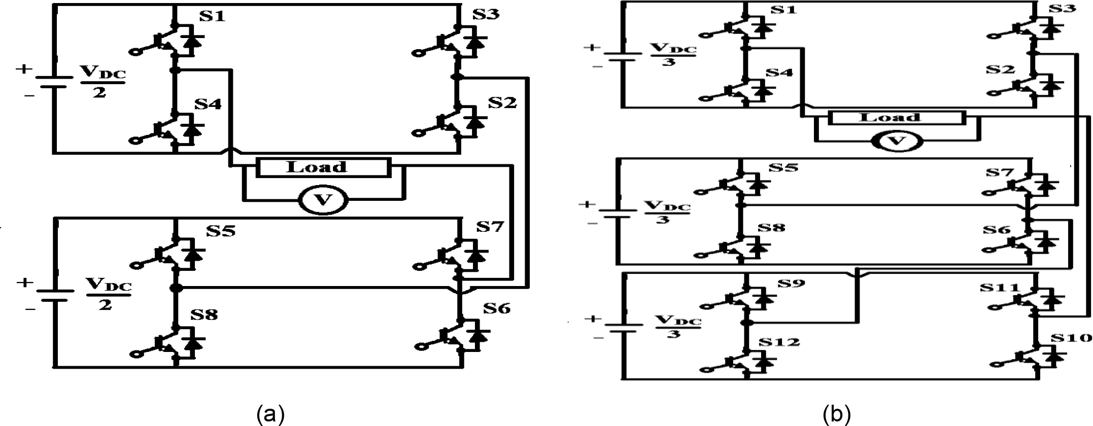
The number of bridges required for 'n' level cascaded H-bridge inverter is '(n-1)/2' per phase, each bridge having four switches. A conventional five level Cascaded H-Bridge Multi Level Inverter(CHB-MLI) topology requires 8 switches per phase as shown in Figure 2(a) and its switching modes are given in Table.2 [23]. A conventional seven level CHB-MLI topology requires 12 switches per phase as shown in Figure 2(b) and its switching modes are given in Table 3. A new five switch seven level MLI topology is proposed which is a maximum switch reduction from the conventional seven level twelve switch MLI topology. The main disadvantages of the conventional seven level 12 switch topology are increased complexity, size, switching losses and cost. The proposed MLI topology consists of four DC sources, five switches and seven levels with low complexity, switching losses, size and cost as depicted in Figure 3 and its switching modes are tabulated in Table.4. The conduction modes are depicted in Figure 4.
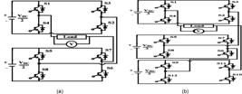
Conventional single phase Cascaded H-Bridge Multilevel Inverter: (a) five-level eight switches; (b) seven-level twelve switches.
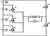
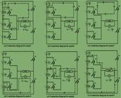
The main purpose of a seven level five switches multilevel inverter is to provide sinusoidal waveforms with low-level harmonic content to reduce distortion in electric distribution network and maximize power efficiency and improving inverter performance with the quality of the output voltage, low switching loss, compact in size, low cost. In each conduction mode operation, only two switches are turned on. The six conduction modes excluding the zero voltage mode are depicted in Figure 4. In zero operation mode, all five switches are off.
METHODOLOGY
The UPQC is the series MLC and shunt MLC compensation device. The voltage appraised power quality issues are mitigated by using series MLC, whereas current appraised power quality issues are mitigated by using shunt MLC. The design of the proposed system configuration is presented in the next subsections.
Choosing DC link capacitor and DC link voltage
A DC link capacitor is designed by equalizing the energy across the capacitor and changing the energy of the system in a load transient state. UPQC's rating is X KVA and the series inverter and shunt inverter share a ratio of 0.4:2. When the load KVA increases, the capacitor starts discharging and hence VDC decreases. For a maximum transient tolerance of 20%, the difference in capacitor energy is given by,
Difference in system power for load increase from 0.4X KVA to 2X KVA is
Where ‘n’ is the no of cycles, ‘T’ is the each cycle periodic time and ‘X’ is the system rating in KVA.
By equating two energy equations, we get the DC link capacitor (Cdc) as
The DC link capacitor voltage (VDC) is 'k' times the maximum voltage of the distribution system voltage (Vmax). The value of 'k' ranges from 1.2 to 2. From the experimental study, the optimum value of k for minimum harmonic distortion is 1.6.
The design of feed forward multilayer neural network-fuzzy (FFMLNN-Fuzzy) based control scheme for seven-level five switch converter (7LFSC-UPQC) is divided into four subsections: (1) Shunt compensator PI control scheme (2) Series compensator PI control scheme (3) Fuzzy control scheme and (4) Feed forward multilayer neural network-fuzzy control scheme. Each subsection is discussed in the following three sections.
Conventional PI control scheme for series compensator
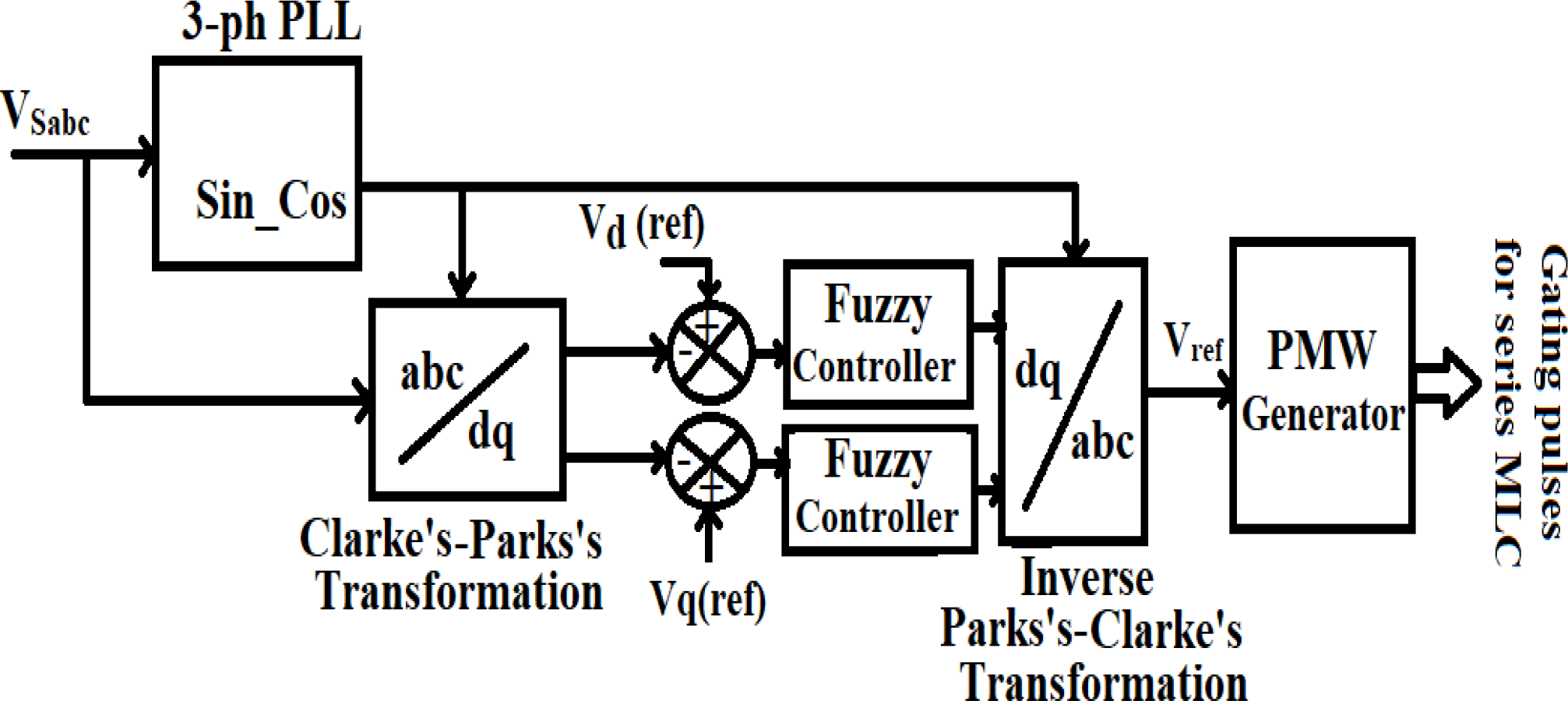
Conventional PI control scheme for series compensator consists of a phase locked loop (PLL), Clarke’s-Park’s transformation block, Inverse Clarke’s-Park’s transformation block, and PWM generator [24]. Based on the phase angle derived from the phase locked loop (PLL) of source voltage, he Clarke-Park transformation (4) converts three-phase voltages into d-q frame voltages, simplifying control by isolating direct and quadrature components. The error signals in (5) and (6) compare actual d-q voltages to their reference values, providing essential feedback for control systems. This approach enables precise voltage regulation, improving system performance and stability in AC systems, and this error signal is fed to the proportional-integral (PI) controller, which then produces reference voltage signals (7). The dq-frame parameters are then converted to a-b-c coordinates using (8) and are taken as reference voltage (VLabc_ref) to produce the final switching pulses for the series compensator of the 7LFSC-UPQC.
The dq-frame parameters are then converted to a-b-c coordinates using (8) and are taken as reference voltage (VLabc_ref).
Conventional PI control scheme for shunt compensator
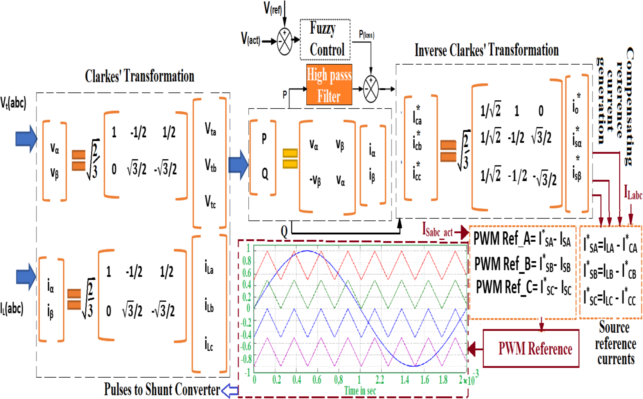
In this control scheme, the DC link voltage can be controlled using a PI controller, which involves more computing time for tuning proportional and integral gain parameters. Active (P) and reactive (Q) powers are calculated from line voltages and currents as in (9) and the angles are calculated from Clarke’s transformation. Compensating reference currents are obtained from PI controller output and active and reactive current components using inverse Clarke’s transformation as in (10).
The source reference currents are obtained by comparing compensating reference current signals and line currents from high/medium industrial distribution system as in (11), (12) & (13):
For ‘m’ level (7 level) multilevel inverter, the number of carriers required is ‘m-1’ (=6) is illustrated in Figure 2. The PWM reference signals are obtained by comparing reference source currents and actual source currents as in (14) as:
Fuzzy control scheme
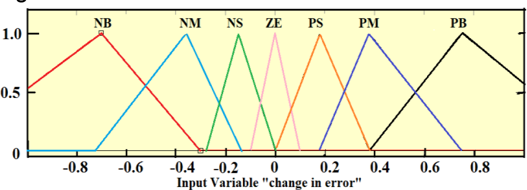
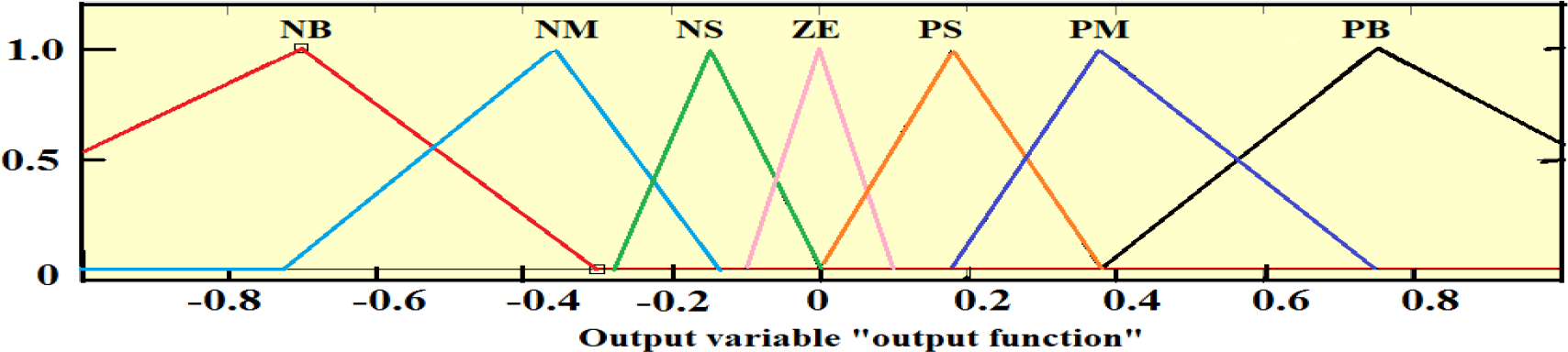
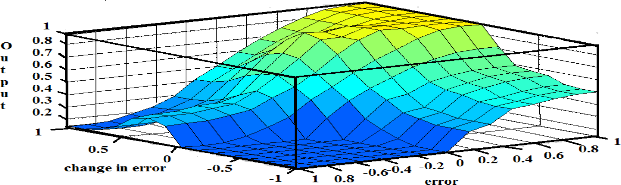
The main disadvantage of a PI controller is more computing time for tuning proportional and integral gain parameters, which can be overcome by a fuzzy control scheme as shown in Figure 1. The DC link voltage can be regulated using a fuzzy logic controller in which triangular membership functions are considered with forty-nine fuzzy rules tabulated in Table 5. The fuzzy system consists of two input membership functions and one output membership function as shown in Figures 5, 6 & 7 respectively. The surface view of error input, change in error input and output functions are shown in Figure 8.
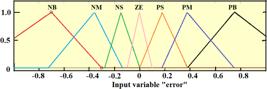
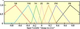
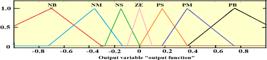
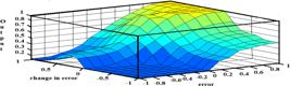
Fuzzy control scheme for shunt compensator is shown in Figure 9, DC link voltage can be controlled using fuzzy controller, in which fuzzification transforms crisp data of error and change in error into linguistic variables, fuzzy inference includes fuzzy rules as tabulated in table.5 and centroid method of defuzzification process using Suzeno fuzzy inference and equations (15), (16) and (17). The active (P) and reactive (Q) powers are calculated from the line voltages and currents as in (9) and the angles are calculated from Clark's transformation. Compensation reference currents are obtained from the fuzzy controller output and active and reactive current components using inverse Clark's transform as in (10) [25].
Fuzzy rule output is given by
Where e and ∆e are the fuzzy inputs. pi and qi are the constant coefficients.
Each rule firing strength (ri) is given by
Here, M1 and M2 are the membership functions of fuzzy inputs
The final output of fuzzy controller from ‘N’ no. of fuzzy rules is calculated by the equation (17).
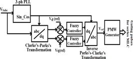
A fuzzy control scheme for a series compensator is shown in Figure10, which consists of a phase locked loop (PLL), a Clarks-Park's transformation block, an inverse Clarks-Park's transformation block, and a PWM generator. Based on the phase angle obtained from the phase locked loop (PLL) of the source voltage, Clarks-Park's transformation block transforms the voltage into rotational 'd-q' coordinate equations using three steps (4). The error signal is obtained by comparing the actual values and the 'd-q' reference signals using (5) & (6) and this error signal is fed to the fuzzy controller using equations (15), (16) and (17), which generates the reference voltage signals. The dq-frame parameters are converted to a-b-c coordinates using (8) and taken as the reference voltage (VLabc_ref) to generate the final switching pulses for the series compensator of the 7LFSC-UPQC.
Feed Forward Multi-Layer Neural Network-Fuzzy control scheme
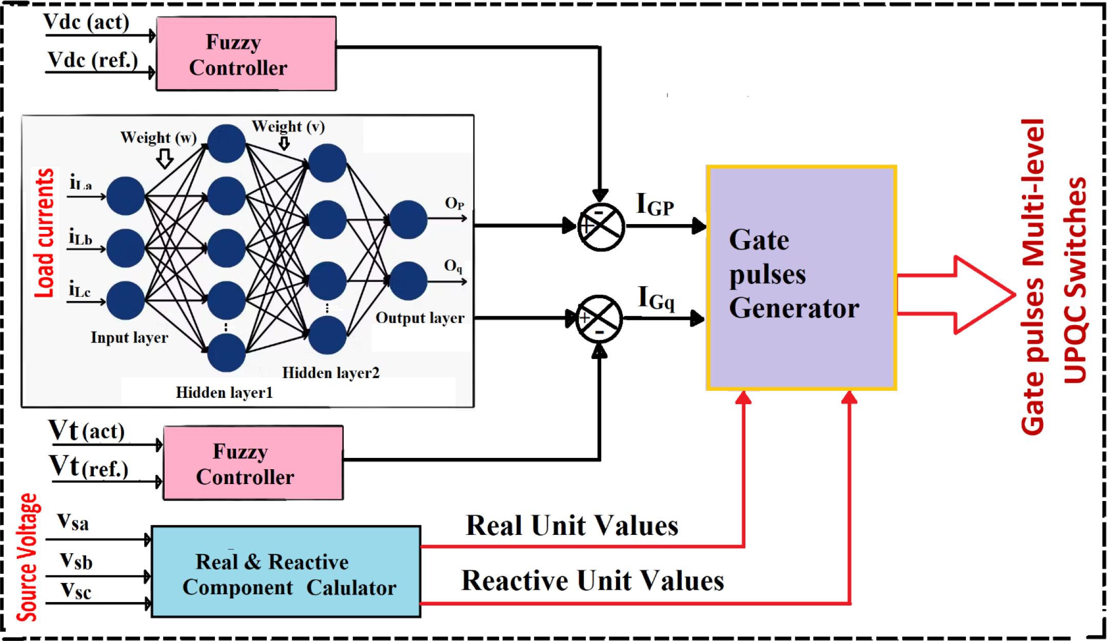
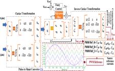
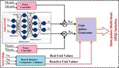
The proposed FFMLNN-fuzzy control scheme is implemented in three stages as in the first stage, the active and reactive power quantities are estimated using the assumed weight vectors (w, v) in the forward direction of the signal propagation as shown in Figure11. In the second step, the errors are reduced by updating the weights using the gradient descent method in the error back propagation direction. In the third step, the DC link voltage and terminal voltage are controlled using a fuzzy controller and compared with the active and reactive power outputs of the neural network. The final error signals are used as reference signals to generate gating pulses to the UPQC.
Fuzzy multi-layer feed forward neural network control scheme for seven-level five switches based UPQC
The loss function of three phase active and quadrature components due to load disturbance can be calculated in forward propagation from input layer to output layer with pre-assumed weight values using sigmoid activation function as follows:
The general output of hidden layer 1 is expressed as:
Where
The general output of hidden layer 2 is expressed as:
Where
The general output signal of neural network algorithm is expressed as:
The load currents are processed through a back propagation-based multi-layer artificial neural network to generate active and reactive component outputs. The general weights (w & v) are updated by using back propagation algorithm as:
Where
Where
The terminal voltage is calculated from the three phase supply voltages using (2) as:
The in-phase unit voltages are estimated as
The quadrature-unit quantities are calculated as
The dc link voltage and the predicted terminal voltage are compared with the actual values and the error signals are provided as inputs to the fuzzy logic controller (5.44) and (5.45):
The reference quantities are calculated from the output quantities of FFMLNN and Fuzzy as follows:
The reference current and voltage quantities are estimated in the form of the following equations:
The three phase error signals for shunt converter of 7LFSC-UPQC are:
The three phase error signals for series converter of 7LFSC-UPQC are:
The error signals (41) are fed to a POD-SPWM technique in order to generate the switching signals for switches S1 to S5 of each phase of 7LFSC-UPQC series VSC. The error signals (42) are fed to a POD-SPWM technique in order to generate the switching signals for switches S’1 to S’5 of each phase of 7LFSC-UPQC series VSC as depicted in Figure 11.
RESULTS AND DISCUSSIONS
The proposed feed forward multilayer neural network based 7LFSC-UPQC is designed in MATLAB with the system parameter specifications shown in Table 1. The simulation is carried under a nonlinear load distorted source voltage with voltage sag, swell, and harmonics condition.
Proposed three phase seven-level five switches converter
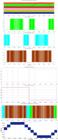
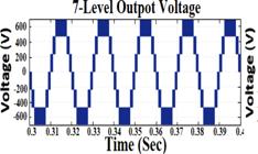
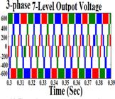
Generation of a suitable pattern of gate pulses plays a vital role in generating the required seven level output voltage. Phase-opposition disposition SPWM (POD-SPWM) technique is used for three phase seven-level five switch structure. The switching pulse pattern for switches S1 to S5 and seven level voltage for one cycle is illustrated in Figure 12. Figure 13 and Figure 14 show the single phase seven level output voltage and three phase seven level output voltage respectively.
Sag and Swell mitigation
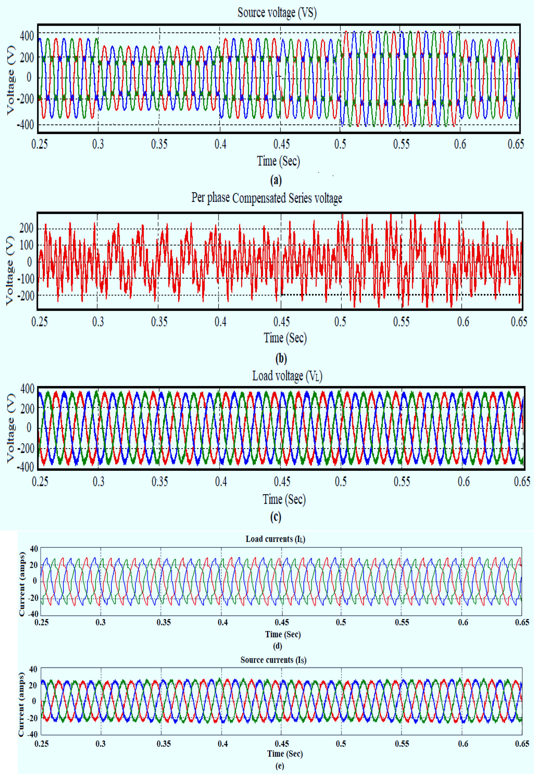
The voltage sag of 20% occurs at t=0.3 sec to 0.4 sec and voltage swell of 20% occurs at t=0.5 sec to 0.6 sec in source voltage as shown in Figure 15 (a). It is observed that voltage sag is compensated by using series converter of FFMLNN-UPQC and voltage swell is compensated by using shunt converter of FFMLNN-UPQC. The per phase series injected voltage, three phase compensated load voltages during sag and swell are depicted in Figure 15 (b) and Figure15(c) respectively. The dynamic performance compensated three phase load currents and compensated source currents during sag and swell are shown in Figure 15 (d) and Figure 15 (e) respectively.
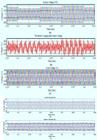
Dynamic performance of source voltage sag-swell, compensation voltage, load voltage, load current and source current
Total Harmonic Distortion
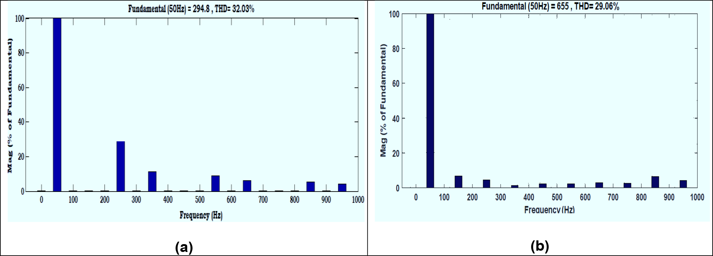
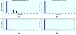
%THD of single phase 7LFSC-UPQC is 29.06% compared to 32.03% of conventional five phase UPQC. Due to polluted power supply, the source voltage with 26% of fifth harmonics and 16% of seventh harmonics, % THD of source voltage and load voltage is 30.53% before compensation using five-level UPQC as shown in Figure 16(a). After compensation, the %THD of load voltage is reduced to 3.98% from 30.53% with the PI controller and reduced to 3.03% with the fuzzy logic controller and further reduced to 1.61% as per the FFT analysis results shown in Figure 16(b), 16(c) & 16(d). Due to non-linear loads and distorted source voltage, the total harmonic distortion (THD) of load currents is 64.27%. From the simulation results, it is observed that the %THD of source current is reduced to 8.49% from 64.27% with the PI controller and reduced to 5.74% with the fuzzy logic controller and further reduced to 3.62% as per the FFT analysis results shown in Figure 17. As per the IEEE standard, the source current total harmonic distortion of < 5% is achieved with the proposed control scheme. The %THD of the load voltage and source current with the PI controller, fuzzy-controller and FFMLNN control scheme results are compared and listed in Table 6.
Comparison of % THD and No. of switches between five-level and proposed seven-level converter
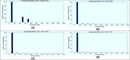
%THD spectrum of Load voltage of five level UPQC (a) before compensation (b) with PI controller (c) with fuzzy controller (d) with FFMLNN-fuzzy controller
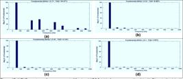
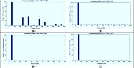
%THD spectrum of source current of five level UPQC (a) before compensation (b) with PI controller (c) with fuzzy controller (d) with FFMLNN-fuzzy controller
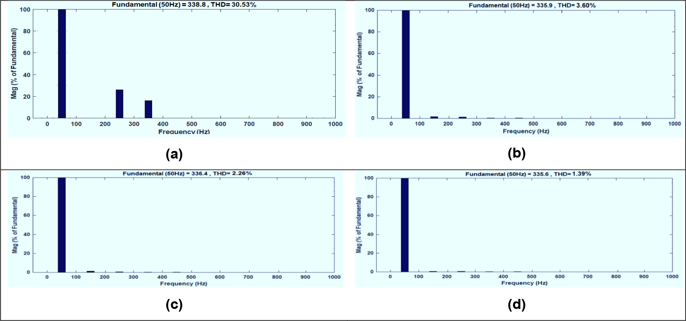
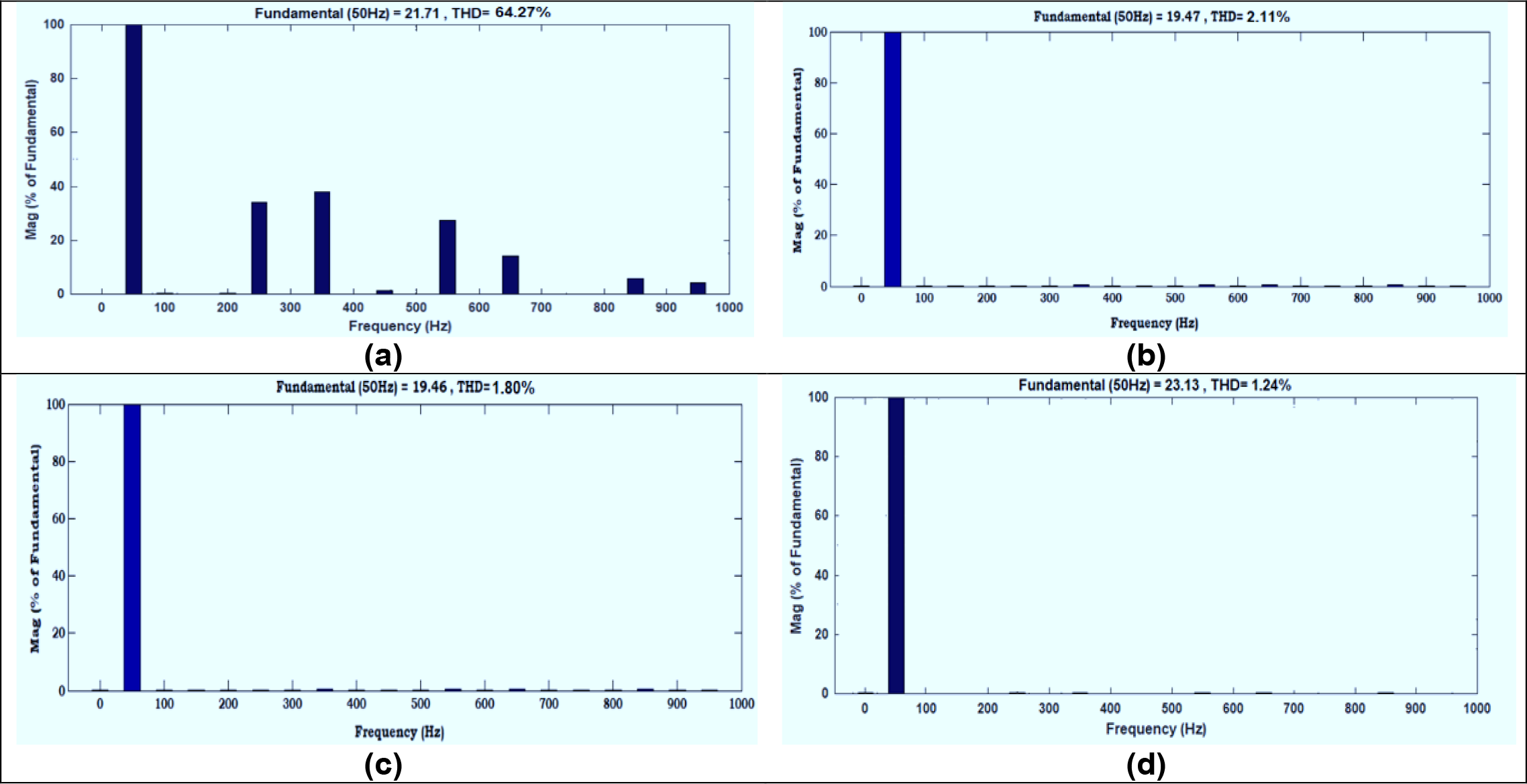
Due to polluted power supply, the source voltage with 26% of fifth harmonics and 16% of seventh harmonics, % THD of source voltage and load voltage is 30.53% before compensation using seven-level UPQC as shown in Figure 18(a). After compensation, the %THD of load voltage is reduced to 3.60% from 30.53% with the PI controller and reduced to 2.26% with the fuzzy logic controller and further reduced to 1.39% as per the FFT analysis results shown in Figure 18(b), 18(c) & 18(d). Due to non-linear loads and distorted source voltage, the total harmonic distortion (THD) of load currents is 64.27%. From the simulation results, it is observed that the %THD of source current is reduced to 2.11% from 64.27% with the PI controller and reduced to 1.80% with the fuzzy logic controller and further reduced to 1.24% as per the FFT analysis results shown in Figure 19. As per the IEEE standard, the source current total harmonic distortion of < 5% is achieved with the proposed control scheme. The %THD of the load voltage and source current with the PI controller, fuzzy-controller and FFMLNN control scheme results are compared and listed in Table 6.
%THD spectrum of Load voltage of seven level UPQC (a) before compensation (b) with PI controller (c) with fuzzy controller (d) with FFMLNN-fuzzy controller
%THD spectrum of source current of seven level UPQC (a) before compensation (b) with PI controller (c) with fuzzy controller (d) with FFMLNN-fuzzy controller
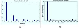
%THD of output voltage of (a) five-level eight switches MLC (b) seven-level five switches MLC
CONCLUSION
This paper has investigated a feed forward multilayer neural network control scheme for three phase five-switch and seven-level configuration based UPQC. This control scheme uses back-propagation algorithm and fuzzy control to generate reference voltages and reference source currents for generating gating pulses to series compensation and shunt compensation respectively. The MATLAB simulation results of the conventional PI, fuzzy and FFMLNN controller are demonstrated. The %THD of the source current using PI controller based 7LFSC-UPQC is reduced from 64.27% to 2.11%, compared to 8.49% THD using PI controller based five level UPQC. The %THD of the source current using fuzzy controller based 7LFSC-UPQC is reduced from 64.27% to 1.80%, compared to 5.74% THD using fuzzy controller based five level UPQC. The %THD of the source current using FFMLNN controller based 7LFSC-UPQC is reduced from 64.27% to 1.24%, compared to 3.62% THD using PI controller based five level UPQC. The proposed 7LFSC-UPQC uses 30 switches compared to 48 switches used by the five level converter based UPQC. It concluded that the performance of the proposed FFMLNN-fuzzy control scheme is more effective over fuzzy controller and PI controller under non-linear load and polluted power supply conditions. A seven-level five switch converter UPQC is presented and proved to be more efficient than a five-level eight switch converter UPQC with respect to lower complexity, lower cost and fewer number of switches.
-
Funding:
This research received no external funding.
Acknowledgments:
The authors would like to thank all those who contributed indirectly to this research.
Data Availability Statement:
Research data are only available upon request for corresponding author.
REFERENCES
-
1 Luo A, Xu Q, Ma F, Chen Y. Overview of power quality analysis and control technology for the smart grid. J Mod Power Syst Clean Energy. 2016 Jan;4(1):1-9. doi: https://doi.org/10.1007/s40565-016-0185-8
» https://doi.org/10.1007/s40565-016-0185-8 -
2 Qashou A, Yousef S, Smadi AA, AlOmari AA. Distribution system power quality compensation using a HSeAPF based on SRF and SMC features. Int J Syst Assur Eng Manag. 2021 Oct;12(5):976-89. doi: https://doi.org/10.1007/s13198-021-01185-w
» https://doi.org/10.1007/s13198-021-01185-w -
3 Eftekharnejad S, Vittal V, Heydt GT, Keel B, Loehr J. Impact of increased penetration of photovoltaic generation on power systems. IEEE Trans Power Syst. 2012 Oct 16;28(2):893-901. doi: https://doi.org/10.1109/TPWRS.2012.2216294
» https://doi.org/10.1109/TPWRS.2012.2216294 -
4 Prabaharan N, Palanisamy K. Analysis of cascaded H-bridge multilevel inverter configuration with double level circuit. IET Power Electron. 2017 Jul;10(9):1023-33. doi: https://doi.org/10.1049/iet-pel.2016.0506
» https://doi.org/10.1049/iet-pel.2016.0506 -
5 Thangaraju I, Muruganandam M, Madheswaran M. Performance Analysis and Experimental Verification of Buck Converter fed DC Series Motor using Hybrid Intelligent Controller with Stability Analysis and Parameter Variations. J Electr Eng Technol. 2015;10(2):518-28. doi: https://doi.org/10.5370/JEET.2015.10.2.518
» https://doi.org/10.5370/JEET.2015.10.2.518 -
6 Harbi I, Rodriguez J, Liegmann E, Makhamreh H, Heldwein ML, Novak M, et al. Model-predictive control of multilevel inverters: Challenges, recent advances, and trends. IEEE Trans Power Electron. 2023 Jun 22;38(9):10845-68. doi: https://doi.org/10.1109/TPEL.2023.3288499
» https://doi.org/10.1109/TPEL.2023.3288499 -
7 Panda AK, Patnaik N. Management of reactive power sharing & power quality improvement with SRF-PAC based UPQC under unbalanced source voltage condition. Int J Electr Power Energy Syst. 2017 Jan 1;84:182-94. doi: https://doi.org/10.1016/j.ijepes.2016.05.010
» https://doi.org/10.1016/j.ijepes.2016.05.010 -
8 Trinh QN, Lee HH. Improvement of unified power quality conditioner performance with enhanced resonant control strategy. IET Gener Transm Distrib. 2014 Dec;8(12):2114-23. doi: https://doi.org/10.1049/iet-gtd.2013.0636
» https://doi.org/10.1049/iet-gtd.2013.0636 -
9 Reddy VV, Kumar DA, Kota VR. A multilevel UPQC for voltage and current quality improvement in distribution system. Int J Power Electron Drive Syst. 2019 Dec 1;10(4):1932. doi: https://doi.org/10.11591/ijpeds.v10.i4.pp1932-1941
» https://doi.org/10.11591/ijpeds.v10.i4.pp1932-1941 -
10 Sadoughi M, Pourdadashnia A, Farhadi-Kangarlu M, Galvani S. PSO-optimized SHE-PWM technique in a cascaded H-bridge multilevel inverter for variable output voltage applications. IEEE Trans Power Electron. 2022 Jan 27;37(7):8065-75. doi: https://doi.org/10.1109/TPEL.2022.3146605
» https://doi.org/10.1109/TPEL.2022.3146605 -
11 Kumar DV, Kota VR. Fuzzy-PI Controller based Modulated Multilevel UPQC under Faulty Conditions. Recent Adv Electr Electron Eng. 2020 Nov 1;13(7):1010-21. doi: https://doi.org/10.2174/2352096513666200828112357
» https://doi.org/10.2174/2352096513666200828112357 -
12 Lee SS, Yang Y, Siwakoti YP. A novel single-stage five-level common-ground-boost-type active neutral-point-clamped (5L-CGBT-ANPC) inverter. IEEE Trans Power Electron. 2020 Nov 12;36(6):6192-6. doi: https://doi.org/10.1109/TPEL.2020.3036784
» https://doi.org/10.1109/TPEL.2020.3036784 -
13 Chen M, Gao C, Yin C, Loh PC. Novel cascaded seven-level inverter with embedded voltage boosting for renewable energy applications. CPSS Trans Power Electron Appl. 2022 Mar;7(1):58-70. doi: https://doi.org/10.24295/CPSSTPEA.2022.00006
» https://doi.org/10.24295/CPSSTPEA.2022.00006 -
14 Das S, Ishrak HM, Hasan MM, Kabir MA. Empirical analysis of power quality using UPQC with hybrid control techniques. Results Eng. 2023 Dec 1;20:101527. doi: https://doi.org/10.1016/j.rineng.2023.101527
» https://doi.org/10.1016/j.rineng.2023.101527 -
15 Subanth Williams A, Mani Malar RS, Ahilan T. EPO Optimized FLC Controller for PQ Improvement in Wind Integrated Power Distribution System. Electr Power Compon Syst. 2023 May 9;51(8):809-21. doi: https://doi.org/10.1080/15325008.2023.2191875
» https://doi.org/10.1080/15325008.2023.2191875 -
16 Krishna D, Sasikala M, Kiranmayi R. FOPI and FOFL controller based UPQC for mitigation of power quality problems in distribution power system. J Electr Eng Technol. 2022 May;17(3):1543-54. doi: https://doi.org/10.1007/s42835-021-00836-2
» https://doi.org/10.1007/s42835-021-00836-2 -
17 Sah P, Singh BK. Power quality improvement using Distribution Static Synchronous Compensator. Comput Electr Eng. 2023 Mar 1;106:108599. doi: https://doi.org/10.1016/j.compeleceng.2023.108599
» https://doi.org/10.1016/j.compeleceng.2023.108599 -
18 Varampati VN, Ashok Kumar DV, Kota VR. Comparative analysis of fuzzy-PI and hybrid fuzzy-multi-layer perceptron network-based UPQC for voltage and current quality improvement. Int J Ambient Energy. 2022 Dec 31;43(1):2912-30. doi: https://doi.org/10.1080/01430750.2020.1858421
» https://doi.org/10.1080/01430750.2020.1858421 -
19 Omer P, Kumar J, Surjan BS. A review on reduced switch count multilevel inverter topologies. IEEE Access. 2020 Jan 28;8:22281-302. doi: https://doi.org/10.1109/ACCESS.2020.2969982
» https://doi.org/10.1109/ACCESS.2020.2969982 -
20 Pham KD, Nguyen NV. Switching loss optimization for a pulsewidth modulation strategy with reduced CMV and improved output harmonic distortion for a three-level NPC converter. IEEE Trans Power Electron. 2022 May 19;37(10):12118-33. doi: https://doi.org/10.1109/TPEL.2022.3176564
» https://doi.org/10.1109/TPEL.2022.3176564 -
21 Nanshikar K, Das S. A Hybrid PWM Strategy for Switching Loss Reduction in Three-Level Inverters. IEEE J Emerg Sel Top Power Electron. 2023 Jun 6. doi: https://doi.org/10.1109/JESTPE.2023.3272237
» https://doi.org/10.1109/JESTPE.2023.3272237 -
22 Sunbul A, Alduraibi A, Zare F. Harmonics mitigation filter for high-power applications. IEEE Access. 2022 Oct 17;10:111406-18. doi: https://doi.org/10.1109/ACCESS.2022.3215072
» https://doi.org/10.1109/ACCESS.2022.3215072 -
23 Barah SS, Behera S. An optimize configuration of H-bridge multilevel inverter. In2021 1st International Conference on Power Electronics and Energy (ICPEE) 2021 Jan 2 (pp. 1-4). IEEE. doi: https://doi.org/10.1109/ICPEE50452.2021.9358533
» https://doi.org/10.1109/ICPEE50452.2021.9358533 -
24 Jha K, Shaik AG. A comprehensive review of power quality mitigation in the scenario of solar PV integration into utility grid. e-Prime Adv Electr Eng Electron Energy 2023 Mar;3:100103. doi: https://doi.org/10.1016/j.prime.2022.100103
» https://doi.org/10.1016/j.prime.2022.100103 -
25 Varshney AK, Torra V. Literature review of the recent trends and applications in various fuzzy rule-based systems. Int J Fuzzy Syst. 2023 Sep;25(6):2163-86. doi: https://doi.org/10.1007/s40815-023-01534-w
» https://doi.org/10.1007/s40815-023-01534-w
-
Editor-in-Chief:
Alexandre Rasi Aoki
-
Associate Editor:
Daniel Navarro Gevers