Abstract:
The use of a transformation method for the passage from one geodetic system to another requires the use of some common points as support points, these points are used in the determination of the transformation parameters. Generally, the choice of the support points is effected manually by choosing the best distribution of these points in the transformation area. In the present study, we present a methodology of selection of these points where an algorithm takes into account the computation of the transformation parameters with all combinations between the common points and the best result will be adopted. An application of this methodology are carried out in North-East of Algeria to determine the best set of the 09 transformation parameters between the WGS84 system and the National North Sahara system using 10 common points (05 support and 05 control). This methodology is efficient in the case where the common points are near one another.
Keywords:
Nine-parameters of transformation; North Sahara Datum; WGS84; Support points; Control points; Combination
1. Introduction
Nowadays, the Global Positioning System (GPS) is widely used in geodetic studies. The GPS uses the World Geodetic System 1984 (WGS84) as a reference ellipsoid (Janssen 2009).
The national geodetic system North Sahara 1959 (NS59) is the basis of all geodetic and cartographic works in Algeria, it was derived (in 1957-1958) from the European Datum 1950 (ED50) by a simple translation of longitude (λNS59=λED50-0.0229° and isometric latitude and referenced to the Clarke 1880 ellipsoid where: semi-major axis, a=6378249.145 m; semi-minor axis, b=6356514.870 m; flatting, f=293.465; and eccentricity, e=0.082483339 (Mugnier 2019; Medjahed and Zeggai 2012).
The transformation of WGS84 coordinates into a local datum becomes a common and frequent task in geodesy. The procedure for converting (transforming) from one coordinate system to another is known as coordinate transformation (Wolf et al. 2014). The purpose of a datum transformation is to provide a mathematical or computational means to transform the coordinates of a point from one datum to another (Ruffhead 2021). This procedure in the case of the transformation from WGS84 to NS59 datum requires the definition of the following elements (Figure 1):
-
Source and target system: WGS84 is the source system and NS59 is the target datum.
-
Transformation parameters: It is the link between WGS84 and NS59 datum, when the transformation parameters are known is sufficient to apply them directly to the coordinates available to obtain their correspondents in the other system, in other cases they need to be estimated from some common points (Andrei 2006)
-
Common points: The set of known points in WGS84 and NS59, the number, distribution and accuracy of these points may influence the accuracy of the transformation (Janssen 2009), these points are divided in support points used in the determination of the transformation parameters and control points used to evaluate the results of transformation.
In this work, we study the effect of the geometry distribution of the support points on the transformation results, where an algorithm takes into account the computation of the transformation parameters with all combinations between the common points and the best result will be adopted.
The present work study is organized as follows: in section 2, we present the mathematical formalism of the 9 parameters transformation model, the section 3 is devoted to the computation of combinations for the creation of the different set of support and control points, in section 4 an application of transformation using 10 common points between WGS84 and NS59 is presented, a summary of conclusions is given.
2. Transformation Model of 9-Parameters
The 7-Parameters transformation model is the general similarity transformation developed by Helmert in 1876, which is well known in the geodetic community as a conformal datum transformation (Abbey et al. 2020), the current form of this model was developed by Burša (1962) and Wolf (1963) known as the Bursa-Wolf model.
The simplified and approximate form of Bursa-Wolf model (7-Parameters) is the most used in geodetic transformations because their simplicity and ease of implementation into software, (Gullu et al. 2017), the general formula of this model is presented in several documents (Deakin 2006; Janssen 2009; Ruffhead 2021):
Where: X 2 the coordinates in target system and X 1 the coordinates in source system, T the translation vector, k scale factor and R rotation matrix result of three rotations about each axis given in (Andrei 2006; Deakin 2006; Ruffhead 2021) by:
Where E x , E y , E z are the rotation angles about X, Y and Z axis.
If the rotations exceed a few arc-seconds, the use the rotation matrix (03) is required (Janssen 2009).
The 7 transformation model (Figure 1) determine three translations, three rotations and a single scale factor (Abbey et al. 2020).
In Equation (01), there a single scale factor to determine, in some case several datum have a problem in orientation and scale factor as the NS59 datum (Medjahed and Zeggai 2012), and to resolve this problem we suppose that each axis has a different scale factor.
The matrix of scale factor K given in (Andrei 2006; Awange et al. 2008; Paláncz and Piroska 2011) by:
Where, K x , K y and K z are the three different scale factors for each axis.
Substituting the scale factor matrix (04) in Equation (01), the model of 7-Parameters becomes a model of 9-Parameters described in the following:
The 9-Parameters transformation model it is an extension of the 7-Parameters transformation model (Awange et al. 2008), the Equation (05) is not linear and needs to be linearized as follows.
1-Translation: The three translations are approximated as:
Where: are the approximate and the corrected values of translation vector.
2-Scale factor: The three scale factors are approximated as:
Where: are the approximate and the corrected values of scale factor matrix.
This leads to formulate the matrix K under the form:
Where: K 0 , M, N, P are 3x3 matrices
3-Rotation: To linearize the rotation matrix, the three rotations are approximated as:
Where: are the approximate and the corrected values of rotation matrix.
The rotation matrix R can be linearized at the approximate values Ex 0 , Ey 0 and Ez 0 as:
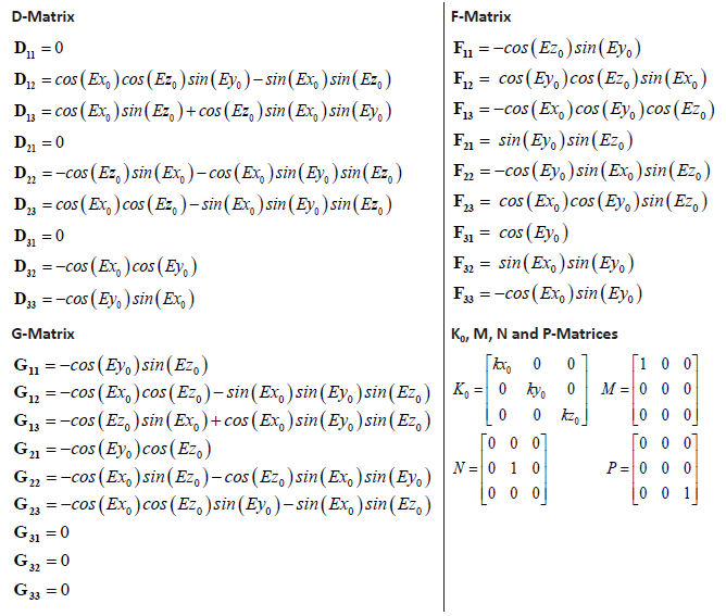
With:
Thus
Where: and D, F, G are 3x3 matrices.
The matrices K 0 , M, N, P of scale factor and R 0 , D, G, F of rotation are provided in Appendix.
Replacing T, K and R in Equation (05) give:
After development of (12) and neglecting the terms of second order , the 9-Parameters transformation model becomes:
By organizing the unknowns in the same vector, the Equation (13) can be written for one support point as:
Where: A is the configuration matrix, B is vector of observations and (X is the vector of the 9 unknown parameters.
The Equation (14) is defined as the problem of 9 transformation parameters of determining three translations parameters, three scales parameters and three rotations parameters in the X, Y and Z directions (Awange et al. 2008).
The solution of system (14) based on least squares method is given in (Deakin 2006; Gullu et al. 2017; Ruffhead 2021; Wolf et al. 2014) by:
Which can be obtained iteratively until convergence as follows:
Where: the vector of the initial values of T 0 , K 0 and R 0 .
The solution of (16) converges very quickly after two or three iterations (Andrei 2006).
The elements of B and A are provided in Appendix.
3. Creation of the Support and Control Points Sets
To use all the common points as support points and create the different sets of points (Figure 3), we will use the combination technique. A combination is a technical term meaning ‘selections’, it is a mathematical technique that determines the number of possible arrangements in a collection of items where the order of the selection does not matter.
Given a set E of P objects, we call combinations any set of N objects among the P objects. The combinations of N objects taken from P objects are denoted with .
In this work study, we asked the following question: How many possibilities to choose N support points from P common points not taking into account the order.
The number given by the formula (17) answers this question (Gordon 1994; Awange et al. 2010).
Where, : N Arrangement of P; P: Number of common points; N: Number of support points; !: Factorial; P-N=M: Number of control points.
4. Application of the 9 Transformation Parameters Model
4.1 Presentation of Data Test
In this application, we determinate the 9 transformation parameters between WGS84 and NS59 datum using 10 common points known in both systems (Figure 2).
If we fixed N the number of support points=05 and M the number of control points = 05, we have C possibilities to choose a set of 05 support points from P=10 common points.
Using the formulas (17) the result is different combinations. This numerical calculation of C can be translated as follows: If we use 05 support points and 05 control points, we have 252 sets of transformation parameters to calculate and each set gives a transformation result.
In this application, the following five support points: (01 02 04 09 10) have the best geographical distribution (Figure 2) and this set of support point is considered as the first choice.
The Figure 3 show the file of the support and control points for 252 sets.
After creating the file of 252 sets, we found that our choice was the set number 36 (Figure 3).
4.2 Results of Set Number 36
The Figure below shows what the solution converge after the second iteration for each parameter, where: is the initial solution.
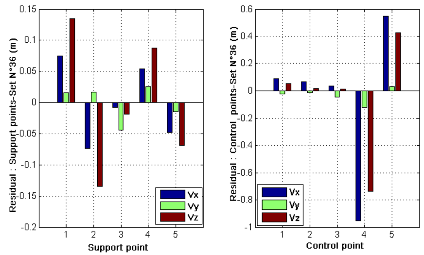
The following Figure shows the residuals in the support and control points.
The residuals have a maximum values in X and Z component and not very significant for the Y component.
4.3. Results of All Combinations (9-Parameters and RMS)
Figures 6, 7 and 8 shows the variation of the transformation parameters in function of combination number, where C=1 to 252.
The variation of the 9 transformation parameters depends on the geometry of the 05 support points. The values limiting the parameters have obtained in the case where the support points are aligned or have a bad distribution as the set number 134 composed by (02-03-04-06-09), the set number 135 composed by (02-03-04- 06 -10), the set number 146 composed by (02-03-05-07-08).
Figure 9 shows the RMS results on support and control points for each set.
On the basis of the numerical and graphical results, we can cite some remarks
-
The best result of transformation were obtained with set number 81 (Figure 10) where the RMS=11.3cm in control points and 35.2cm in support point.
-
The worst case in terms of transformation results is obtained with the set number 148 (Figure 10) where the RMS is 26.7cm in support points and is 454cm in control point, these results are due to the aligned geometry of the five support points.
-
In section 2 we have used the set number 36 (Figure 2), for this set, the RMS = 36.2cm in control points and 6.7cm in support points.
-
The methodology used for the choice of support points has retained the set number 81 as the best choice.
-
A difference of 24.9cm in the control points between set number 81 and set number 36 was observed, this difference is very important in geodetic application
-
For the set number 81, the transformation parameters were used outside their determination area.
-
The use of the points border the transformation area as support points is not always efficient.
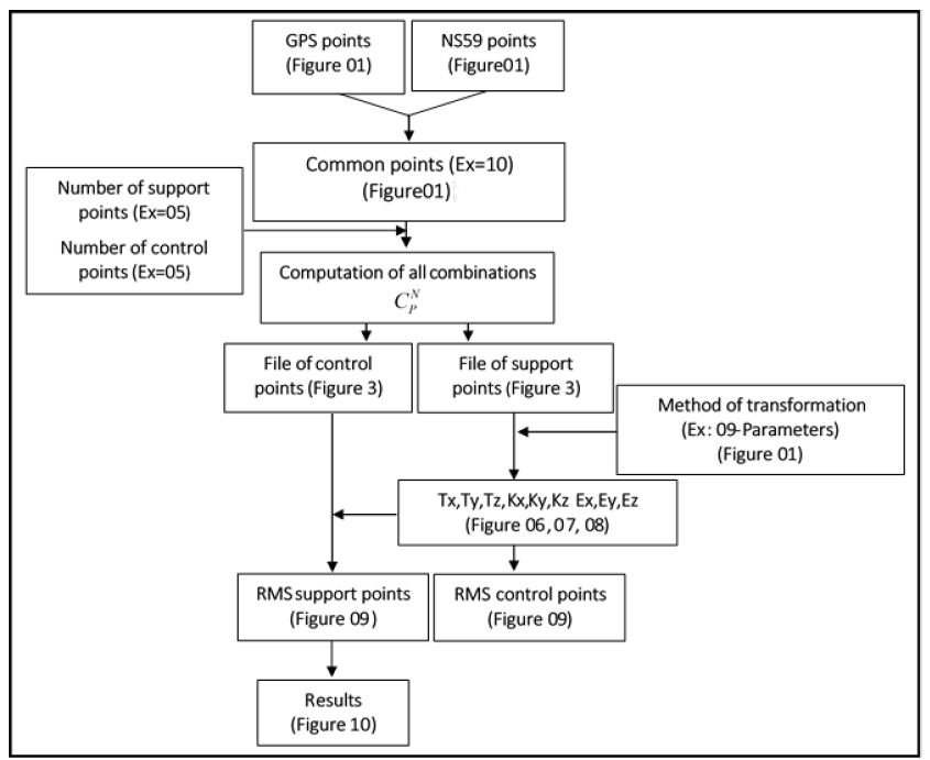
Figure 11, summarizes the calculation steps followed in this work-study.
5. Conclusions
The transformation of GPS coordinates into national geodetic North Sahara system (NS59) are the subject of this paper, this transformation is related to the choice of support points selected from the common points, this choice has an important influence on the quality of the transformation results.
The objective of this study is the presentation of selection methodology of the support points where an algorithm takes into account all possible combinations between the common points and the best result will be retained in function of the RMS minimum value.
The North Sahara geodetic system have a problem in orientation and scale factor (lack of information) and for this we have used the 9 parameter transformation model where the scale factor parameter is replaced by three scale factors.
The methodology presented in the present work can be applied with any transformation model (Bursa-Wolf, Molodensky, polynomial transformation, leveling/GPS...) and can be applied to identify the support points used in the computation of the transformation parameters.
REFERENCES
-
Abbey, D.A. and Featherstone, W.E. 2020. Comparative review of Molodensky-Badekas and Burša-Wolf methods for coordinate transformation. Journal of Surveying Engineering, 146 (3), 04020010. https://doi.org/10.1061/(ASCE)SU.1943-5428.0000319
» https://doi.org/10.1061/(ASCE)SU.1943-5428.0000319 -
Andrei, O.C. 2006. 3D affine coordinate transformations. Masters of Science. School of Architecture and the Built Environment, Royal Institute of Technology (KTH), 100 44 Stockholm, Sweden. http://learning.aols.org/aols/3D_Affine_Coordinate_Transformations.pdf
» http://learning.aols.org/aols/3D_Affine_Coordinate_Transformations.pdf -
Awange, J.L., Bae, K.-H., and Claessens, S.J. 2008. Procrustean solution of the 9-parameter transformation problem. Earth, Planets and Space, 60 (6), pp.529-537. https://doi.org/10.1186/BF03353115
» https://doi.org/10.1186/BF03353115 -
Awange, J.L., Grafarend, E.W., Paláncz, B., and Zaletnyik, P. 2010. Algebraic Geodesy and Geoinformatics 2nd ed., Berlin, Heidelberg: Springer Berlin Heidelberg. https://doi.org/10.1007/978-3-642-12124-1
» https://doi.org/10.1007/978-3-642-12124-1 -
Deakin, R. E. 2006. A note on the Bursa-Wolf and Molodensky-Badekas transformations. School of Mathematical and Geospatial Sciences, RMIT University, pp.1-21. http://www.mygeodesy.id.au/documents/Similarity%20Transforms.pdf
» http://www.mygeodesy.id.au/documents/Similarity%20Transforms.pdf - Gordon, S. 1994. Counting Techniques, Mathematics Learning Centre, University of Sydney, NSW 2006.
-
Gullu, M., Yilmaz, M., and Baybura, T. 2017. Comparative analysis of least-squares approaches for 3D datum transformation in Western Turkey. Afyon Kocatepe University Journal of Sciences and Engineering, 17 (3), pp.1019-1029. https://doi.org/10.5578/fmbd.66171
» https://doi.org/10.5578/fmbd.66171 -
Janssen, V. 2009. Understanding coordinate systems, datums and transformations in Australia. In: Surveying & Spatial Sciences Institute Biennial International Conference (SSC2009), pp. 697-715. Adelaide. https://eprints.utas.edu.au/9489/
» https://eprints.utas.edu.au/9489/ - Medjahed, S., Zeggai, A. 2012. Elaboration d’une grille de conversion de coordonnées géographiques -Application à la région d’Oran [Elaboration of a conversion grid of geographical coordinates -Application to the Oran region]. Review XYZ, 131(2), pp. 47-51.
-
Mugnier, C.J. 2019. Democratic and Popular Republic of Algeria. Photogrammetric Engineering & Remote Sensing, 85 (7), pp.475-478. https://doi.org/10.14358/PERS.85.7.475
» https://doi.org/10.14358/PERS.85.7.475 -
Paláncz, B. and Piroska, Z. 2011. A symbolic solution of a 3D affine transformation. The Mathematica Journal, 13. https://doi.org/10.3888/tmj.13-9
» https://doi.org/10.3888/tmj.13-9 -
Ruffhead, C. 2021. Investigation into the accuracy and practicality of methods for transforming coordinates between geodetic datums. Doctor of Philosophy. School of Architecture, Computing and Engineering, University of East London. https://doi.org/10.15123/uel.89w80
» https://doi.org/10.15123/uel.89w80 - Wolf, P.R., Dewitt, B.A., Wilkinson, B.E. 2014. Elements of Photogrammetry with Applications in GIS 4th Edition. McGraw-Hill Education
APPENDIX
R0-Matrix: Given by Equation (03)
The 9-Parameters transformation model given by Equation (13): need the computation of the following matrices:
Scale factor parameters:
Rotation parameters:
Observation vector:
Coefficients of B-Vector: We have and
Coefficients of A-Matrix: We have:

 Study of the geometry influence of the support points in coordonates transformation: application from WGS84 to NS59 datum


