
 Quality control of Cone Beam Computed Tomography (CBCT) equipment used in dental applications according to RDC 611
Abstract
Cone Beam Computed Tomography (CBCT) is a powerful and a versatile tool that has revolutionized the way dentists plan and perform treatments. Several advantages are attributed to this modality, including: the equipment is compact, image acquisition is fast, it has high spatial resolution and produces detailed images. However, when compared to other imaging diagnostic methods used in dentistry, CBCT often administers higher doses, emphasizing the need for careful use and the application of radiation protection principles. For example, the effective dose of an intraoral radiograph is less than 1.5 µSv. The effective dose of a panoramic radiograph ranges between 2.7 and 24.3 µSv, while the effective dose of a CBCT scan ranges from 64 to 674 µSv. This study evaluated a CBCT device that underwent the tests recommended by current Brazilian regulations, assessed the doses generated by the device, and implemented a quality assurance program in a dental radiology service that uses this technology, to promote maximum efficiency, safety, and accuracy, optimizing the radiation doses administered and ensuring the quality of the images acquired. This is the first step in the development of a quality control (QC) protocol for the service under evaluation. It is part of the implementation of a certification program to be applied initially in the Galeão Air Force Hospital (HFAG) service, which will serve as a model for other radiology services of the Brazilian Air Force.
Keywords:
CBCT; CQ protocol; Radiology Service; Dental Applications
Resumo
A Tomografia Computadorizada de Feixe Cônico (TCFC) é uma ferramenta poderosa e versátil que revolucionou a maneira como os dentistas planejam e realizam tratamentos. Várias vantagens são atribuídas a essa modalidade, entre elas: o equipamento é compacto, a aquisição de imagens é rápida, tem alta resolução espacial e produz imagens detalhadas. No entanto, quando comparado a outros métodos de diagnóstico por imagem usados na odontologia, a CBCT frequentemente administra doses mais altas, enfatizando a necessidade de uso cuidadoso e a aplicação de princípios de radioproteção. Como exemplo, a dose efetiva de uma radiografia intraoral é menor que 1,5 µSv. A dose efetiva de uma radiografia panorâmica varia entre 2,7 e 24,3 µSv, enquanto a dose efetiva de um exame de CBCT varia de 64 a 674 µSv. Este estudo avaliou um aparelho de TCFC que passou pelos testes recomendados pela regulamentação brasileira vigente, avaliou as doses geradas pelo aparelho e implementou um programa de garantia da qualidade em um serviço de radiologia odontológica que utiliza essa tecnologia, para promover a máxima eficiência, segurança e precisão, otimizando as doses de radiação administradas e garantindo a qualidade das imagens adquiridas. Este é o primeiro passo no desenvolvimento de um protocolo de controle da qualidade (CQ) para o serviço em avaliação. Faz parte da implementação de um programa de certificação a ser aplicado inicialmente no serviço do Hospital da Força Aérea do Galeão (HFAG), que servirá de modelo para outros serviços de radiologia da Força Aérea Brasileira.
Palavras-chave:
CBCT; Protocolo de CQ; Serviço de Radiologia; Aplicações Odontológicas
1. INTRODUCTION
Cone Beam Computed Tomography (CBCT) is a powerful and versatile tool that has revolutionized the way dentists plan and perform treatments. Unlike CT scanners, which have a narrow beam and are used in most medical procedures, cone beam equipment allows the acquisition of images of a larger anatomical region in a single exposure. This fact causes a significant reduction in radiation dose of the procedure [1]. The data is processed by a computer to generate detailed three-dimensional images of the areas examined and, for this reason, the technique has been widely used in dentistry. Several advantages are attributed to this modality, including: the equipment is compact, image acquisition is fast (which improves the efficiency of diagnosis and treatment planning), it has high spatial resolution, produces detailed images and generates lower radiation dose values, compared to those associated with medical computed tomography (which is a significant benefit for patients and professionals) [1]. It is difficult to establish how many times more radiation CBCT releases compared to intraoral and extraoral radiographs, because the radiation dose of CT varies according to the scanned area, the thickness of the slice, the adjustments of the device, as well as the type of CBCT machine [1]. However, when compared to other imaging diagnostic methods used in dentistry, CBCT often administers higher doses, emphasizing the need for careful use and the application of radiation protection principles. As an example, the effective dose of an intraoral radiograph is less than 1.5 µSv. The effective dose of a panoramic radiograph varies between 2.7 and 24.3 µSv, while the effective dose of a CBCT scan ranges from 64 to 674 µSv [1, 2, 3, 4, 5].
Quantifying the level of patient exposure in any medical procedure is complex due to the variation of several parameters, such as patient thickness, size of the irradiation field, etc. This quantification becomes even more complex in procedures that involve movement of the X-ray source and variable exposure times, as is the case with CBCT [5, 6].
To determine the levels of exposure in CBCT, kerma-length product (P KL ) or kerma-area product (P KA ) are normally used, thus determining dose indicators. This measurement requires some special care and precision in the measurement process.
1.1. Kerma-length product and kerma-area product
The main quantities used to assess dosimetry in cone beam tomography are: kerma-length product (P KL ) and kerma-area product (P KA ), quantities derived from basic physical quantities. The kerma-length product (P KL ) is the quantity used in radiological physics, particularly in computed tomography (CT), to assess the amount of energy that is transferred to air by the x-ray beam over a specific length, z. The air kerma–length product is the integral of the air kerma free-in-air over a line L parallel to the axis of rotation of a CT scanner [7, 8]. Kerma is a quantity that measures the energy absorbed per unit mass, while length refers to the length of the x-ray beam used during the scan. It is defined by equation 1:
The SI unit of P KL is Gy × m. Knowledge of the values of kerma-length products is important in assessing the risk of exposure to ionizing radiation and in optimizing the radiation dose in medical procedures.
The quantity air kerma–area product is the integral of the air kerma free-in-air over the area A of the x-ray beam in a plane perpendicular to the beam axis. (equation 2). It is a surrogate measurement for the entire amount of energy delivered to the patient by the X-ray beam [8].
P KA is the integral of the air kerma applied to the projection of the area of the X-ray beam onto the detector. The SI unit of P KA is Gy×m 2 . It is commonly used in diagnostic radiology to assess the radiation dose absorbed by patients during imaging exams, such as radiographs, computed tomography scans and fluoroscopy.
In Brazil, to comply with the requirements of ANVISA's Collegiate Board Resolution RDC 611 [9], published in 2021, many medical and dental radiology services have implemented Quality Assurance programs [10], like international practices [11]. Developing these Quality Assurance programs in Dental Radiology is essential in the current landscape of dental radiology services to ensure quality care, particularly in services that use ionizing radiation. This aspect must be closely monitored due to the risks involved [6].
Most CBCT equipment offers a standard dental protocol with acquisition parameters and voxel sizes suitable for an average patient. However, the operator can select, from a range of dental protocols, the most one appropriated based on the clinical needs and anatomical characteristics of each patient. Since the primary radiation dose received by the patient depends on the irradiated region and the selected exposure parameters, it is important to choose the dental protocol that provides the lowest dose while offering the necessary diagnostic information [12, 13], always respecting the ALARA principle ("As Low as Reasonably Achievable"). Protocols should, therefore, be created to reduce absorbed doses in dental exams, as radiosensitive structures, such as the thyroid, salivary glands, and eyes, may be within or near the primary radiation field.
One of the fundamental steps in establishing a quality assurance program or even in certifying a service is to test the relevant parameters of the radiological equipment to correct possible inconsistencies in its operation. The values obtained in this first assessment will serve as a reference for monitoring its performance over time. Once the equipment reaches optimal operation by adapting all technical parameters, it will be possible to move forward in seeking quality certification.
This study aims to evaluate a CBCT device that has undergone the tests recommended by current Brazilian regulations, assess the doses generated by the device, and implement a quality assurance program in a dental radiology service that uses this technology, to promote maximum efficiency, safety, and accuracy, optimizing the radiation doses administered and ensuring the quality of the images acquired. This is the first step in developing a QC protocol for the service under evaluation. It is part of the implementation of a certification program to be applied initially in the HFAG service, which will serve as a model for other radiology services of the Brazilian Air Force.
2. MATERIALS AND METHODS
The present study was developed in the dental radiology department of the Galeão Air Force Hospital (HFAG), located in Rio de Janeiro. The dental radiology department is equipped with 12 intraoral radiography devices, distributed across 12 consultation rooms, in addition to an Instrumentarium cone beam tomograph model Orthopantomograph OP300 (Figure 1).

In addition to tomography, the device also allows for panoramic and cephalometric examinations, depending on the operator's initial selection. Despite being multifunctional, only the tomographic modality was evaluated in this study. The tomograph uses an X-ray tube with a nominal voltage of 90 kV. Parameters such as field of view (FOV - 3D area captured by the scanner during the imaging process), current-time product, and nominal P KA are variable and depend on the programs available for taking the exam (Table 1).
In the present study, the quality control (QC) protocol proposed by Lisboa [6] was implemented, which provided a step-by-step guide for performing QC procedures in compliance with national legislation, using international documents as references [14, 15, 16]. The minimum instrumentation required for performance testing includes a solid-state detector capable of measuring parameters such as tube voltage, exposure time, air kerma (and air kerma rate), and half-value layer; an ionization chamber calibrated for air kerma or kerma- area product; an image quality phantom that allows for the measurement of image uniformity and the evaluation of CT numbers; and an image plate from a computed radiography system to measure the field of view.
The quality control tests on equipment, in tomographic mode, were conducted in accordance with the requirements outlined in the current Brazilian regulations — ANVISA's Collegiate Board Resolution (RDC) number 611 [9]. There are 18 evaluations established in Normative Instruction number 94, from May 2021 [17]. They are necessary to verify the proper functionality of the tomograph, all its components, and other procedures related to the safety of those involved in radiography and the assurance of diagnostic quality (Table 2).
2.1. X-Ray tube
The parameters related to the equipment's X-ray tube were evaluated using a Radcal Accu-Gold AGMS-D solid-state detector connected to a digitizer, which transmits the information to a computer (Figure 2).

Once the detector is multiparametric, the parameters as voltage accuracy and its reproducibility, exposure time accuracy and its reproducibility, and half-value layer were evaluated in a single exposure. Six exposures were performed for the same program suggested by the equipment (which offered the longest exposure time — FOV 61 x 78 mm², current 6.3 mA, and 13 seconds of exposure time).
P KA values were determined using a pencil-type ionization chamber, manufactured by Radcal, model 10X6-3CT, paired with an electrometer (Accu Dose 9095). This pencil-type ionization chamber was placed in the center of the image detector. An image plate (IP) from a CR radiography system was used to determine the actual field size, (i.e. area = length, b multiplied by height, h) employed during irradiations. Figures 3 and 4 illustrate the experimental setup. From the air kerma measurement, the kerma-length product was calculated using equation 3 (length of the chamber = 10 cm) and from this P KL value, using equation 4, the P KA value was calculated.
P KL = 10 (cm) × kerma (mGy)
(3)
P KA = P KL (mGy × cm) × h (cm)
(4)
The parameters dose indicator accuracy and air kerma rate accuracy were analyzed using the Accu-Gold AGMS-D solid-state detector placed in the center of the CBCT equipment's imaging detector.


2.2. Physical space and radiation protection accessories
The radiometric survey was conducted using a Radcal 9095 electrometer and an 1800 cm³ ionization chamber, model 10X6-1800 (Figure 5). Measurements were taken at the points indicated in the room diagram (Figure 6). The areas that were analyzed were those surrounding the exam room. The measurements were made in places where there is a greater presence of people. Points A, B and C refer to the control room, where the exam is performed. Point D refers to the dental office that is located next to the exam room (point E).


To evaluate the illuminance of the reporting room and the luminance of the primary and secondary monitors, a lux meter, model Light-o-meter P10 by Unfors, was used. The device was operated in ambient lighting mode.
The integrity of accessories and personal protective equipment was assessed through visual inspection.
2.3. Tomographic image
To evaluate the tomographic image, a phantom made of polymethyl methacrylate (PMMA) was exposed. The phantom consists of a homogeneous region — used for assessing image uniformity — and another region used to evaluate the indicated value and uniformity of CT numbers, with structures equivalent to materials such as air, PMMA itself, and polytetrafluoroethylene (PTFE), commonly known as Teflon. The phantom, supplied by the X-ray equipment manufacturer, is shown in Figure 7.

Next, a visual inspection of the phantom's tomographic images was performed using software integrated into the tomographic system, as recommended by the European Protocol [15] and the Spanish Quality Control Protocol in Diagnostic Radiology [16]. The evaluation included the presence or absence of artifacts in the image, the indicated value and uniformity of the CT number, and noise.
3. RESULTS AND DISCUSSION
3.1. X-ray Tube
Table 3 presents a comparison between the results obtained from measurements of the parameters related to the X-ray tube voltage and exposure time, and the tolerances established by IN 94/RDC 611 [9].
The results show that the HVL, the accuracy and the reproducibility of the tube voltage comply with the tolerances established in the norm. The measured voltage showed minimal variation from the nominal value, indicating that the system was stable and delivered the nominal voltage value (accuracy deviation less than 1%). When evaluating the consistency of the results, the system also demonstrated high reproducibility, as the maximum deviation among the six readings was less than 0.5%.
The six-time readings were found to be inaccurate, with an accuracy deviation of 19%. However, the readings presented no variation. Although the measured values deviated by 19% from the protocol value, there was no variation among the obtained results, demonstrating measurement stability. Despite this non-compliance, the restriction threshold established in the IN was not exceeded (20%). The technical support service needs to be contacted to adjust the X-ray equipment to comply the normative indices, ensuring its full functionality and preventing it from impacting other parameters, especially the patient dose, given the direct relationship between these two parameters.
To verify the reproducibility of the air kerma, six exposures were also performed using the same program suggested by the equipment (with the longest exposure time: FOV 61 x 78 mm², current 6.3 mA, and exposure time of 13 seconds), resulting in a reproducibility of 0.08%, demonstrating compliance with the legislation. According to IN 94, air kerma reproducibility must be ≤ 10%.
The height of the radiation field (h) was measured with a cassette used in computed radiography (CR) positioned at the detector entrance, yielding a result of (10.3 ± 0.1) cm. A radiopaque object was used as a reference to correct the image magnification effect. The field size was measured with a calibrated ruler in centimeters with a precision of 1 mm. According to the manufacturer's manual, the image detector area is 100 x 68.2 mm, confirming that the radiation field is confined to the device's detector.
The CBCT dental equipment studied in this work provides a dose estimate for each suggested technique before exposure. The calculated P KA values were obtained by multiplying the measured P KL values by the height of the irradiation field. However, the results showed that the nominal P KA values were underestimated by up to 34% compared to the calculated P KA values. In other words, the value indicated by the equipment is up to 34% lower than the measured representative dose value.
Table 4 shows the obtained results.
Comparison between nominal and calculated P KA values. The last column shows the percentage difference between these values.
It is possible to see that the equipment does not provide accurate information about the exposure in patients. This fact may be directly related to the results obtained in the exposure time accuracy test. Therefore, adjustments in the equipment are necessary. Similar results can be found in the literature, such as those obtained in this study [18, 19, 20], which allows us to infer that most commercial brands provide underestimated doses. It is necessary to perform the necessary adjustments on the equipment to correct these underestimations.
Consequently, it was immediately requested that the representative dose values be adjusted through a correction factor. Figure 8 shows the linear adjustment used. The measured P KA values are plotted on the y-axis, while the nominal P KA values are on the x- axis.

Linear adjustment plotted to determine the equation that allows the correction of the calculated P KA value.
The correlation between both quantities was determined to be linear, because its R² is approximately 1. This relation was given by equation 5.
Corrected P KA = (1,248 x Nominal P KA ) + 2,26
(5)
The equation 5 must be used to correct the equipment’s P KA values and, with these results, should be established a dose reference level (DLR), aiming to know those doses applied on the service. The knowledge of the doses received by the patients will allow us to go forward at a practice optimization, inside of a set of action proposed at a QC program that we intend to implement.
3.2. Physical Spaces and radiation protection accessories
The radiometric survey was done using the parameters that produce the highest dose. It was also considered a workload of 50 weeks per year. The limits established at IN 94 [17], for free areas are 0.5 mSv/year, while at controlled areas are 5 mSv/year. The results showed that the calculated value was below those limits, showing that the wall’s shielding is protecting the external areas from unacceptable dose rate levels. All measurements performed at each monitored point were satisfactory, demonstrating that the shielding is within the established limits.
The illuminance of the reporting room was measured under conditions that replicate the professionals’ working environment, yielding a result of 8 lux in front of the monitor. According to IN 94 [17], the tolerance value for the illuminance of the reporting room should be less than 50 lux, indicating that the room meets the ideal conditions.
The luminance of the reading monitor was measured using a radiography image from the computer's memory. This was done because the evaluated service's monitor is not specialized for this function. Measurements were taken in both bright and dark areas. The bright area presented a luminance of (42.5 ± 0.1) cd/m², while the dark area presented a luminance of (10.5 ± 0.1) cd/m². According to IN 94 [17], the luminance should be greater than or equal to 170 cd/m², indicating that the results were below expectations or that the applied methodology at is not ideal for this evaluation.
The integrity of accessories was visually assessed and found to be in compliance.
3.3. Tomographic Image
For the assessment of the tomographic image (image uniformity, indicated CT number value in three distinct materials – water, Teflon and air, CT number uniformity and noise). Figure 9 shows the image for the evaluation of image uniformity and noise.
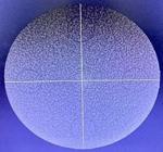
PMMA image obtained by tomographic acquisition. It is possible to see the regions of interest (ROIs).
The presence or absence of artifacts in the image was visually evaluated, and no artifacts were identified, in accordance with IN 94 [17]. The results of the indicated CT number values for each element of the phantom were in agreement with the values established in the reference (equipment user manual). Regarding the uniformity of the CT number, the values also presented within the expected range, indicating that the generated image has an adequate signal, in addition to being uniform and having low noise (Table 5).
According to IN 94 [17], the CT number should not vary by more than 10% from the reference values established by the manufacturers, and the noise levels should be less than 15% of the reference value.
Based on the results obtained from the 18 evaluations established in IN 94 [17], we verified that most parameters are complying (14 tests), and only 4 tests presented results outside the established tolerances: exposure time accuracy, dose representative values (P KA ), dose indicator accuracy, and monitor luminance for radiological reports.
The tests recommended in the normative configure a minimum set of evaluations to comply with legal requirements, but they are not the only ones that can be performed. A medical physicist responsible for quality control can and should expand the set of evaluations to optimize protection for all those involved in radiation exposure and improve image quality, thereby facilitating radiographic diagnosis. A quality assurance program should not be limited to only legal requirements, and the more evaluations performed, the easier it will be to ensure quality, safe, and efficient service in its processes. This would be the first step towards developing a certification program to be implemented, with subsequent reflections on professional training, process standardization, and automation of administrative procedures, seeking management professionalization, cost reduction, and consequently, excellence.
4. CONCLUSIONS
High-quality CTFC examinations are vital for accurate diagnoses, effective treatment planning, error reduction, and safe and efficient patient experience. The synergy of advanced technology and technical expertise is critical to optimize the benefits of this imaging modality, highlighting the need for established protocols.
The tube voltage and the half value layer presented stable and compliant with the established normative. However, the exposure time values were found to be non-compliant. Similarly, the representative dose values were outside the expected values determined by the Normative Instruction, but still within the tolerance limit. Therefore, although within tolerance levels, the equipment can be used. The radiometric survey of the installation was found to be compatible with the applied doses in the service, since the dose levels in each evaluated area are in accordance with the established normative for each type of area.
The equipment needs to be adjusted so that the parameters related to exposure time, dose representative values, and dose indicator accuracy are exact. It is also recommended that the radiological report monitors be specific for this purpose, aiming for excellence in image evaluation. The quality control tests of the equipment must be repeated periodically in accordance with the established normative
Equipment quality control allowed the characterization of its performance and dosimetry parameters, as well as the identification of indicators that require adjustments and the establishment of baseline values for future quality control tests. The next steps in establishing a certification program, the ultimate goal of this project, will involve conducting a rigorous evaluation that encompasses aspects such as professional qualification, radiological safety procedures, quality management, and other aspects related to service delivery. This will be an important indicator that a healthcare institution meets established standards and is committed to continuous improvement of quality and patient safety.
The implementation of a QC program would therefore enable the strengthening of respect and positive image of the service before patients, collaborators, and society, in addition to its operational efficiency serving as a quality reference to be followed.
This research was supported by the Galeão Air Force Hospital and the Radioprotection and Dosimetry Institute of the National Nuclear Energy Commission. We would like to thank for the encouragement, support for the development of this work and for recognizing the value of continuous study and always encouraging it. To the IRD and its employees for their support, provided resources, and commitment to academic excellence. To all who collaborated directly or indirectly in the realization of this work.
REFERENCES
-
1 GARIB, D. G. et al. Tomografia computadorizada de feixe cônico (cone beam): entendendo este novo método de diagnóstico por imagem com promissora aplicabilidade na ortodontia. Revista Dental Press de Ortodontia e Ortopedia Facial, SciELO Brasil, v. 12, p. 139–156, 2007.
» https://doi.org/10.1590/S1415-54192007000200018» https://doi.org/10.1590/S1415-54192007000200018 -
2 COHNEN, M. et al. Radiation dose in dental radiology. European Radiology, Springer, v. 12, n. 3, p. 634–637, 2002.
» https://doi.org/10.1007/s003300100928» https://doi.org/10.1007/s003300100928 - 3 HORNER, K. et al. European guidelines on radiation protection in dental radiology: the safe use of radiographs in dental practice. European commission, directorate-general for energy and transport. radiation protection. Brussel, Belgium EU, 2004.
- 4 HORNER, K. et al. Cone beam CT for dental and maxillofacial radiology (Evidence based guidelines). European Commission, Directorate-General for Energy X11, 2012.
-
5 LUDLOW, J. B. et al. Dosimetry of 3 cone beam computed tomography devices for oral and maxillofacial radiology: Cb mercuray, newtom 3g and i-cat. Dentomaxillofacial radiology, British Institute of Radiology, v. 35, n. 4, p. 219–226, 2006.
» https://doi.org/10.1259/dmfr/14340323» https://doi.org/10.1259/dmfr/14340323 - 6 LISBOA, B. F.O. Programa de Garanta de Qualidade em Radiologia Odontológica. Aplicação em um serviço de Tomografia de Feixe Cônico. Dissertação (mestrado) – Instituto de Radioproteção e Dosimetria. Rio de Janeiro, 2024.
-
7 ICRU, 2005. Patient dosimetry for X rays used in medical imaging. ICRU Report 74. Journal of the ICRU Vol 5 No 2 (2005).
» https://doi.org/10.1093/jicru_ndi016» https://doi.org/10.1093/jicru_ndi016 - 8 IAEA International Atomic Energy Agency. Dosimetry in diagnostic radiology: an international code of practice. Technical Reports Series no. 457, ISSN 0074–1914. Vienna, 2007.
-
9 ANVISA. AGÊNCIA NACIONAL DE VIGILÂNCIA SANITÁRIA. Resolução da Diretoria Colegiada - RDC 611. Disponível em: <https://www.in.gov.br/en/web/dou/-/resolucao-rdc-n-611-de-9-de-marco-de-2022- 386107075>. Acesso em: 28/08/2024.
» https://www.in.gov.br/en/web/dou/-/resolucao-rdc-n-611-de-9-de-marco-de-2022-386107075 -
10 COLÉGIO BRASILEIRO DE RADIOLOGIA (CBR). Programa de Acreditação em Diagnóstico por Imagem (PADI), Versão 4, de 01/01/2019. Disponível em: <https://padi.org.br/wp-content/uploads/2023/12/Norma-Padi-Versao-5.1.pdf>. Acesso em: 20/08/2024.
» https://padi.org.br/wp-content/uploads/2023/12/Norma-Padi-Versao-5.1.pdf -
11 THE JOINT COMMISSION SENTINEL EVENT ALERT 47. Radiation risks of diagnostic imaging and fluoroscopy, de 02/2019. Disponível em: <https://www.jointcommission.org/resources/patient-safety-topics.>. Acesso em: 28/08/2024
» https://doi.org/10.22478/ufpb.2317-6725.2023v28n49.66598» https://www.jointcommission.org/resources/patient-safety-topics. - 12 ROCHA, R. A. Otimização da relação dose x qualidade de imagem para Tomografia Computadorizada Cone Beam em implantodontia. Dissertação (mestrado) – Instituto de Radioproteção e Dosimetria. Rio de Janeiro, 2013.
- 13 NASCIMENTO, H.A.R.D. Dosimetria em Tomografia Computadorizada de feixe Cônico com diferentes protocolos. Tese de conclusão de curso - Universidade Estadual de Campinas. Piracicaba, 2016.
- 14 AGÊNCIA INTERNACIONAL DE ENERGIA ATÔMICA. Protocolos de control de calidad para Radiodiagnóstico en América Latina y el Caribe - TEC- DOC 1958. Viena, 2021.
-
15 GALA, H. de L. H. et al. Quality control in cone-beam computed tomography EFOMP-ESTRO-IAEA protocol (summary report). Physica Medica, Elsevier, v. 39, p. 67–72, 2017.
» https://doi.org/10.1016/j.ejmp.2017.05.069» https://doi.org/10.1016/j.ejmp.2017.05.069 - 16 SOCIEDADE ESPANHOLA DE FÍSICA MÉDICA. Protocolo Español de Control de Calidad em Radiodiagnóstico. Revisão 2. Madrid, 2011.
-
17 ANVISA. AGÊNCIA NACIONAL DE VIGILÂNCIA SANITÁRIA. Instrução Normativa IN nº 94, de 27 de maio de 2021. Disponível em: <https://www.in.gov.br/en/web/dou/-/instrucao-normativa-in-n-94-de-27-de-maio- de-2021-*-413249375>. Acesso em: 30/08/2024.
» https://www.in.gov.br/en/web/dou/-/instrucao-normativa-in-n-94-de-27-de-maio-de-2021-*-413249375 - 18 INTERNATIONAL ELECTROTECHNICAL COMMISSION. Evaluation and routine testing in medical imaging departments–Part 3-1: Acceptance tests Imaging performance of X-ray equipment. IEC 61223-3-1. 1993.
- 19 BATISTA, W. O. G. Dosimetria e controle de qualidade em procedimentos radiológicos destinados a implantes odontológicos. Tese (Doutorado) - Universidade Federal de Sergipe. São Cristóvão, 2012.
- 20 OLIVEIRA, M. V. L. de. Avaliação dosimétrica de exames de tomografia computadorizada de feixe cônico em imagens da articulação temporomandibular. Dissertação (mestrado) - Universidade Federal da Bahia - Instituto de Ciências da Saúde. Salvador, 2013.
Edited by
-
SCIENTIFIC EDITOR:
Prof. Dr. Bernardo Maranhão Dantas http://orcid.org/0000-0002-2388-6073
-
SCIENTIFIC EDITOR:
Prof. Dr. Alfredo Lopes Ferreira Filho http://orcid.org/0000-0002-0806-1284

 Source: The authorsFigure 1: Instrumentarium’s Orthopantomograph OP300.
 Source: The authorsFigure 2: Detector Accu Gold AGMS-D positioned on the tomograph image receptor.
 Source: The authorsFigure 3: Ionization chamber and electrometer.
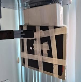 Source: The authorsFigure 4: IP positioned on the image receptor to determine the field size used on irradiation.
 Source: The authorsFigure 5: Ionization chamber positioned to perform the radiometric survey.
 Source: The authorsFigure 6: Diagram of the room showing monitored points during the radiometric survey, including lead glass, shutter button, control room, dental office, and examination room.
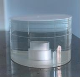 Source: The authorsFigure 7: PMMA phantom used for image quality control.
 Source: The authorsLinear adjustment used to correct the calculated PKA value.
 Source: The authorsPMMA phantom tomographic image showing ROIs.