Sextuple Stepped-Impedance Resonator Antenna for Multiband Wireless Communication Systems
Abstract
This article presents the design and analysis of a sextuple-patch antenna fabricated on Flame Retardant 4 (FR-4) substrate having a copper cladding of 0.5mm for the radiating patches and the ground plane. The antenna can operate at six distinct frequencies, 0.9 GHz, 1.2 GHz, 1.5 GHz, 2.5 GHz, 2.7 GHz, and 3.6 GHz, all of which fall within the communication bands of GSM, GPS, DCS, UMTS, and IEEE 802.11b/g. This versatility renders the antenna highly suitable for various communication devices. To achieve high gain and hexa-band characteristics at the resonant frequencies, the stepped-impedance resonator technique is implemented. The designed antenna's front surface is covered with rectangular-shaped radiating elements while the rear surface is the ground layer. Simulation results confirm that the antenna exhibits very good performance in terms of high gain across the specified frequencies and maintains a favourable impedance matching of 50Ω to observe minimal transmission losses. To ensure compactness and ease of integration with other circuits, the antenna is fed using a coaxial feeding technique. CST Studio is employed to design and validate the antenna's performance. The advanced features and capabilities of the designed antenna make it a compelling choice for integration into smart communication devices.
Index Terms
Multiband; microstrip patch; coaxial feeding; FR-4; SIR; UMTS; WiMAX; WLAN; DCS; GSM.
I. INTRODUCTION
With the rise in the development of modern communication systems, people of contemporary times are becoming more addicted to communication devices from all over the globe. For better communication and data sharing, different electronic devices with different frequency bands are being utilized. Nowadays, as the demand for high data rates and more reliable networks is increasing each day, researchers are also concerned about a compact device that can have the ability to work in different frequency bands. The rise of internet of things (IoT) and next the generation sub-6 GHz would enable more efficient networks that are supposed to increase comfort for users, this involves applications like smart cars, efficient home appliances, and many more which can be controlled using smart devices via the next generation sub-6 GHz bandwidth which it would be offering for better performance.
As antennas are an essential role holder in wireless communication, it is believed that instead of using different antennas within an electronic device for communication at different frequencies, an antenna with the ability to work at different frequencies would be a proper candidate. The requirements of an efficient communication society can be fulfilled by unitizing the features of microstrip patch antenna as these can be designed in different shapes and sizes. Microstrip patch antennas are widely used for modern communication systems because of their advanced features like low profile, lightweight and can easily be integrated inside complex devices. Moreover, antennas can be designed using different simulation software for evaluation before fabrication. The significant frequencies which are used for communication devices range from 0.9 GHz to 5.5 GHz. This frequency range encompasses various applications, including GSM (0.88-0.96 GHz), GPS (1.56-1.59 GHz), DCS (1.71-1.88 GHz), Personal Communication System (1.85-1.99 GHz), UMTS (1.92-2.17 GHz), and IEEE 802.11 b/g (2.4-2.48 GHz) [1]-[4].
In literature, many techniques have been investigated by researchers and accomplished acceptable results. These techniques include amendments in shapes and sizes of radiation structure geometry, different substrate layers, the addition of different substrates together to form multilayer substrates, U-slot array, microstrip monopole antenna, and stacked structure method [1]-[6]. U-shaped and S-shaped antenna have been proposed in [1] which is designed using the physical structure of two different antennas working at different frequencies. This increases the size, and the geometry of the antenna. A multiband C-Slot patch antenna with dual-patch radiating elements is proposed [2], it covers a volume of 50x50x1.57 mm including the ground plane. It contains two parallel C-Slots on the patch elements that are employed to perturb the surface current paths for excitation of the dual-band. Two pin diodes are placed inside the connection lines. The diodes are utilized for the connection and disconnection of patches to obtain the desired dual band. The model proposed in [2] is a bit complex because of the diodes placed in the connection line for obtaining dual band. Secondly, it cannot be easily utilized in handheld devices or in other compact electronic devices that are used for communication. Similarly, in [3], a novel planar monopole antenna is designed which is E-shaped and is fed using a 50 Ω coplanar waveguide transmission line. This antenna can operate in two different frequencies which can support the band frequencies of WiMAX and PCS. Different methods and techniques have been investigated to accomplish multiband characteristics. Multilayer substrates are utilized in [4] which are designed on three different substrate layers and is fed using an electromagnetic coupling method. The electromagnetic coupling feeding technique has complex fabrication methods as compared to other feeding techniques like microstrip line and coaxial feeding methods. Some researchers have achieved multiband attributes using stacked structure design and array formation of radiating patches [5], [6]. Planar multiband antenna-based CRLH is presented in [7], and a multi-layered design was proposed in [8], these antennae have marked acceptable gain and high bandwidth. Although the methods and techniques presented above have accomplished dual band and multiband characteristics [9]-[11], some other issues like complex geometry, high gain, and accuracy need to be resolved.
In this article, a novel methodology is proposed to enhance the multiband antenna characteristics with high gain and good impedance matching. The designed antenna can operate at six different frequencies which are required for different communication applications. The proposed antenna is composed of six radiating elements which are integrated to form a T-shaped antenna. The key contributions of this article are as follows:
-
• The application of a stepped impedance technique to achieve hexa-band characteristics, enhancing the antenna's suitability for several recent communication systems.
-
• The proposed techniques not only improve the antenna's multiband capabilities but also simplify its design when compared to existing methods reported in literature.
-
• The proposed antenna is efficiently fed using a coaxial feeding method, which is well-suited for electronic communication devices and enables seamless integration.
II. ANTENNA STRUCTURE AND DESIGN METHODOLOGY
The microstrip patch antenna proposed in this article is implemented using the FR-4 dielectric substrate, and copper as the conducting material. The width, W, of the designed microstrip patch antenna is determined using (1) while the length, L, of the patch is calculated using (2), where co is the speed of light in free space, f is the center frequency, λ is the wavelength, ɛ is the dielectric constant of the substrate material. The change in the length, ∆L, of the microstrip patch antenna is determined by (3) and the effective dielectric constant, ɛeff, of the substrate material is determined by (4), where h is the substrate height/thickness. The combined structure of the designed antenna is shown in Fig. 1.

The designed antenna consists of four main parts; the radiating patches, the ground plane, the dielectric substrate which is comprised of FR-4 with a relative permittivity value of 4.3 and the stepped impedance acts as a short circuit between the ground plane and the radiating patches. Several dielectric materials were investigated like liquid crystal polymer, roger 3003, and FR-4 [12]-[16]. These substrates were considered because of magnificent features like low cost, remaining stable in different environments, easy availability, and low permittivity [13]. However, FR-4 is selected for the designing of the antenna because of its environment-friendly features and negligible harmful effects compared to other substrates, FR-4 material is cheaper than Roger’s material and can be manufactured in bulk within a low budget. FR-4 material is well known for its feature to maintain its high mechanical values and electrical insulating qualities in both dry and humid conditions [14]. FR-4 has relatively stable dielectric properties over a wide range of frequencies. This stability is important for maintaining consistent antenna performance and allows for more predictable design outcomes. FR-4 provides good electrical insulation, preventing unwanted coupling or interference between the microstrip patch antenna and nearby conductive elements [15], [16]. The presented antenna is fed using a coaxial feeding method.
In literature, many techniques have been implemented to feed the microstrip patch antenna which includes microstrip line, coaxial probe (both contacting schemes), aperture coupling, and proximity coupling (both non-contacting schemes) [17]-[19]. Coaxial feed techniques often result in improved impedance matching, especially when compared to other feeding methods. This can contribute to a broader bandwidth, allowing the microstrip patch antenna to operate effectively over a range of frequencies [16]. The dimensions of the antenna are described in Table I. The wider horizontal rectangular patch P1 shown in the figure is responsible for the first frequency band of 0.9 GHz and the narrower rectangular patch P2 is accountable for 1.5 GHz. Similarly, the vertical wider rectangular patch P3 placed adjacent to the P1 is performing the 1.2 GHz and the thinner patch P4 placed next to the P3 is responsible for frequency operating at 2.75 GHz. The radiating patches placed vertically downwards P5 and P6 are responsible for the frequencies 2.5 GHz and 3.65 GHz. The radiating patches have different lengths and widths which cover an overall size of 85x50x1.574 mm. Radiating patches placed above the dielectric substrate form a T-shape which is shown in Fig. 1. The first radiating patch P1 has a length and width of 24.9x4 mm, second patch P2 is placed horizontally at the top of P1 having a rectangular structure consisting of 17.4x0.45 mm. The third radiating patch P3 comprises 27.8x4.88 mm which is connected to the fourth radiating element P4 having a length and width of 15.50x1.1 mm, correspondingly the fifth and sixth radiating element P5 has a length of 19.25 mm and width of 3.4 mm and P6 consist of 12.26x0.11 mm. The stepped impedance technique is applied to accomplish the multiband characteristic with an improved gain and radiation pattern. For obtaining it a thin circular copper attachment is placed inside the substrate which connects the ground and P1 radiating element. The intended resonators are fed using a coaxial feeding method and the simulated results illustrate perfect matching of 50 Ω is achieved and maximum power is delivered to the radiating elements from the transmission line. The dimensions of the proposed antenna are listed in Table I.
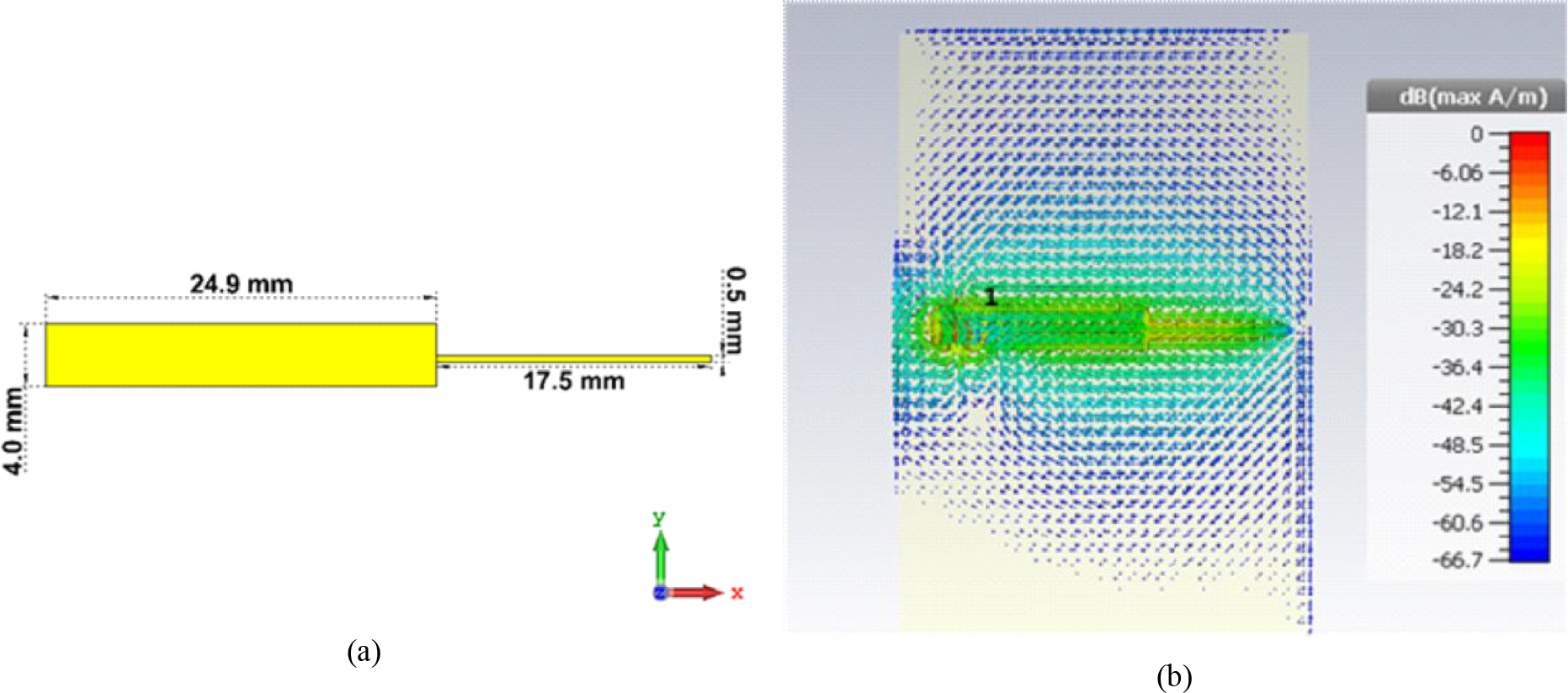
In the initial steps, two radiating patches were designed according to the resonating frequency of 0.9 GHz and 1.2 GHz. The electrical calculations are based on (2) and the techniques reported in [20]-[22]. The dimensions of the substrate are identical to those of the ground plane. The length, Lg, and width, Wg, of the ground plane are determined using (5) and (6) [11], [19]. The electrical measurements of the double patch antenna were designed as shown in the Fig. 2a. The surface current of the double patch antenna illustrates a good distribution of current over the radiating elements as shown in Fig. 2b. The patches are shot-circuited in the middle of the patch and the ground plane to achieve the stepped impedance which improved the current density in the radiating rectangular radiators and results in high gain. Stepped-impedance resonators can be configured to support multiple resonant frequencies. This enables the microstrip patch antenna to operate across different frequency bands, making it suitable for multiband communication systems.

The quadruple antenna was designed to achieve the radiating element with the ability to work at four different frequencies. Two rectangular radiating elements are added to the double-patch antenna. The added elements are responsible for the frequencies operating at 1.5 GHz and 2.51 GHz. The added rectangular patches are shown in the given Fig 3. They are similar to the first two radiating elements shown in Fig. 2 but are rotated to the vertical axis as indicated in Fig. 1 and have different dimensions. The structure of the patches is shown in Fig. 3a while the current distribution is shown in Fig. 3b. The current distribution image shows that most of the current is coming from the feeding port and getting distributed between the two rectangular patches.
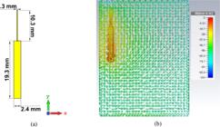
The first two vertically radiating elements P3 and P4: (a) Dimensions. (b) Current distribution.
The remaining two rectangular patches (P5 and P6) are designed according to the electrical measurement of their frequencies and the permittivity of the substrate material. Patches P5 and P6 are responsible for the 2.75 GHz and 3.45 GHz frequencies. They are vertically aligned to the y-axis and their dimensions and current distribution are shown in Fig. 4. The dimensions of the patches are minimally different when compared to the other four radiating patches (P1, P2, P3, and P4). The current distributed in these last two vertical patches confirms that the overall antenna current distribution is acceptable.

The last two vertically radiating elements P5 and P6: (a) Dimensions. (b) Current distribution.
The methodology applied in the design of the proposed sextuple stepped-impedance resonator may be summarized in eight simple steps as follows:
-
i. Choose the initial design specifications including operating frequencies and substate materials.
-
ii. Determine the design dimensions using Equations (1) to (6).
-
iii. Choose the electronic design automation (EDA) software tool to be employed in the proposed design simulation.
-
iv. Decide on the antenna feeding technique to be implemented in the design.
-
v. Implement the design based on the dimensions determined in step ii.
-
vi. Simulate and optimize your design using the EDA software choice made in step iii.
-
vii. Collect and present results including the gains, the reflection coefficients, and the radiation patterns both in the E- and the H-planes.
-
viii. Compare design performance to related state-of-the-art publications (i.e., papers published in the last five years).
III. ANTENNA PERFORMANCE AND DISCUSSION
The assessment of the antenna's effectiveness relies on attaining acceptable values for critical parameters such as the reflection coefficients (S11 or return loss). This metric gauges the amount of power reflected by the antenna, thus earning its designation as the reflection coefficient. Additionally, the evaluation and analysis encompass considerations of impedance matching and the distribution of current across the antenna.
The designed antenna simulation was performed using the CST Studio EDA software tool and the reflection coefficient results presented in Fig. 5. The return loss, which is better than 10 dB provides evidence that the signal is effectively radiated. The attainment of multiple frequencies signifies successful power delivery to the antenna's radiating elements with minimal losses, establishing the antenna's multiband characteristics. The initial three frequency bands at 0.9 GHz, 1.2 GHz, and 1.5 GHz exhibit return losses below -10 dB, yielding a bandwidth of 1.2 GHz. Furthermore, the fourth and fifth frequency bands at 2.5 GHz and 2.75 GHz meet the commercially acceptable standard of -6 dB. The sixth frequency band at 3.65 GHz also exhibits a return loss below -10 dB. These frequency bands align with useful ranges for personal communication systems including wireless LAN, ISM, and WiMAX. The proposed antenna functions across various frequency bands, including L-band, S-band, and WiMAX, with operating frequencies falling within the ranges of 1-2 GHz, 2-4 GHz, and 2.5-2.69 GHz, respectively.

The antenna radiation pattern is shown in Fig. 6 and illustrates that the surrounding angles are perfectly covered. At 0.9 Ghz and 1.2 GHz, the angular width is 95°. Similarly, at the next resonating frequencies 1.5 GHz and 2.51 GHz, the antenna angular width is slightly decreased to 91°. The simulation results of the E-plane and H-plane shown in Fig. 6 shows good coverage and contains some nulls which are common in high-frequency antenna applications. The proposed sextuple antenna recorded good gains at the six operating bands. At the frequencies of 0.9 GHz and 1.2 GHz, it achieved 3.73 dBi gain. With increase in frequency, the designed antenna gain stepped up as well. At the frequencies of 1.5 GHz and 2.51 GHz, the gain reached 5.38 dBi. In the same way, the antenna's angular width also increased. The antenna gain rises at the resonating frequencies of 2.75 GHz and 3.65 GHz, achieving a markable gain of 6.49 dBi. The performance of the antenna radiation pattern and gain is acceptable and makes it suitable for multiple frequency applications. E-plane and H-plane radiation patterns shown in Fig. 6 show that the magnitude of the main lobe is 54° and offers an angular width of 65.7°. Some minimal side lobes can be observed.
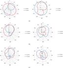
E- and H-plane radiation Patterns at: (a) 0.9 and 1.2 GHz. (b) 1.5 and 2.51 GHz. (c) 2.75 and 3.62 GHz.
The hexa-band antenna presented in this paper utilized a coaxial feeding technique to make it compact and easily integrable for smart communication devices. The antenna is perfectly matched at 50 Ohms by properly locating the probe which is located inside the primary radiating elements. As the designed antenna operates at multiple frequencies, for accuracy, a higher return loss is required and has been accomplished using the coaxial feeding technique. Table II demonstrates the validity of the proposed design and how it compares with the current state-of-the-art related literature [23]-[28] published in the last five years (between 2021 and 2025).
PERFORMANCE COMPARISON OF THE PROPOSED SEXTUPLE ANTENNA WITH RELATED STATE-OF-THE-ART PUBLICATIONS
IV. CONCLUSION
A sextuple antenna has been presented in this article. The antenna exhibits a multiband characteristic with high gain and acceptable bandwidth. The article reported on the methodology and analysis of the antenna design and presented vital results. The stepped-impedance resonator technique has been utilized to achieve multiband characteristics and make a simple design by short-circuiting the radiating elements and ground plane. The top side of the presented antenna is covered with six radiating patches whereas the bottom side is the ground layer. The antenna is fed using the coaxial feeding method. Overall, the reported antenna covers a reduced footprint of 85x50x1.574 mm and has accomplished six resonating frequencies which are widely used in wireless communication systems. The proposed antenna gain and performance are good which makes it suitable for applications in compact wireless communication devices. The utilization of stepped-impedance resonators and the coaxial feeding technique in the proposed antenna demonstrates added merits of simple design and ease of integration with other communication subsystems. SIR devices are generally well known for their easy fabrication/manufacturing process.
REFERENCES
- [1] Yang, G., Zhang, Y. and Zhang, S., 2021. Wide-band and wide-angle scanning phased array antenna for mobile communication system. IEEE Open Journal of Antennas and Propagation, 2, pp.203-212.
- [2] Abutarboush, H.F., Nilavalan, R., Cheung, S.W., Nasr, K.M., Peter, T., Budimir, D. and Al-Raweshidy, H., 2011. A reconfigurable wideband and multiband antenna using dual-patch elements for compact wireless devices. IEEE transactions on antennas and propagation, 60(1), pp.36-43.
- [3] Zhang, Q.T., Jiao, Y.C., Ding, Y. and Li, B., 2011, May. Design of a planar monopole multiband antenna with U-and L-shaped slots. In 2011 IEEE international conference on microwave technology & computational electromagnetics (pp. 331-333). IEEE.
- [4] Firdausi, A. and Alaydrus, M., 2016, October. Designing multiband multilayered microstrip antenna for mmWave applications. In 2016 International Conference on Radar, Antenna, Microwave, Electronics, and Telecommunications (ICRAMET) (pp. 99-102). IEEE.
- [5] Ur Rehman, S. and Alkanhal, M.A., 2019. System modelling and synthesis of stepped impedance resonators and filters. IET Microwaves, Antennas & Propagation, 13(15), pp.2693-2700.
- [6] Jabin, D., Singh, A.K., Srinivas, G. and Tripathi, V.S., 2014, May. Double U-slot loaded stacked microstrip patch antenna with 2× 2 array for multiband operation. In 2014 Students Conference on Engineering and Systems (pp. 1-3). IEEE.
- [7] Saeed, M.A. and Nwajana, A., 2022, October. A novel beamforming antenna array for 5G and beyond applications. In 2022 International Conference on Engineering and Emerging Technologies (ICEET) (pp. 1-4). IEEE.
- [8] Saeed, M.A., Obi, E.R. and Nwajana, A.O., 2024. A compact linear microstrip patch beamformer antenna array for millimeter-wave future communication. Sensors, 24(13), p.4068.
- [9] Saeed, M.A. and Nwajana, A.O., 2024, October. Design of a rectangular linear microstrip patch antenna array for 5G communication. In 2024 IEEE International Symposium on Phased Array Systems and Technology (ARRAY) (pp. 1-4). IEEE.
- [10] Huang, C., Jiao, Y.C., Weng, Z.B. and Li, X., 2018, March. A planar multiband antenna based on CRLH-TL ZOR for 4G compact mobile terminal applications. In 2018 International Workshop on Antenna Technology (iWAT) (pp. 1-3). IEEE.
- [11] Saeed, M.A. and Nwajana, A., 2023, September. U-shaped terahertz microstrip patch antenna for 6G future communications. In 2023 7th International Electromagnetic Compatibility Conference (EMC Turkiye) (pp. 1-4). IEEE.
- [12] Askarian, A. and Wu, K., 2020, July. Shared-aperture enabled integration of Sub-6 GHz and millimeter-wave antennas for future multi-functional wireless systems. In 2020 IEEE International Symposium on Antennas and Propagation and North American Radio Science Meeting (pp. 1775-1776). IEEE.
- [13] Shah, I.A., Hayat, S., Khan, I., Alam, I., Ullah, S. and Afridi, A., 2016. A compact, tri-band and 9-shape reconfigurable antenna for WiFi, WiMAX and WLAN applications. International Journal of Wireless and Microwave Technologies, 6(5), pp.45-53.
- [14] Iqbal, A., Ullah, S., Naeem, U., Basir, A. and Ali, U., 2017. Design, fabrication and measurement of a compact, frequency reconfigurable, modified T-shape planar antenna for portable applications. Journal of Electrical Engineering and Technology, 12(4), pp.1611-1618.
- [15] Saikia, B., Dutta, P. and Borah, K., 2020. Design of a frequency reconfigurable microstrip patch antenna for multiband applications. In Proceedings of the 5th International Conference on Computers & Management Skills (ICCM 2019)| North Eastern Regional Institute of Science & Technology (NERIST), Nirjuli, Arunachal Pradesh, India
- [16] Ullah, S., Ahmad, I., Raheem, Y., Ullah, S., Ahmad, T. and Habib, U., 2020, March. Hexagonal shaped CPW feed based frequency reconfigurable antenna for WLAN and sub-6 GHz 5G applications. In 2020 International Conference on Emerging Trends in Smart Technologies (ICETST) (pp. 1-4). IEEE.
- [17] Abdulraheem, Y.I., Oguntala, G.A., Abdullah, A.S., Mohammed, H.J., Ali, R.A., Abd-Alhameed, R.A. and Noras, J.M., 2017. Design of frequency reconfigurable multiband compact antenna using two PIN diodes for WLAN/WiMAX applications. IET Microwaves, Antennas & Propagation, 11(8), pp.1098-1105.
- [18] Khan, T., Rahman, M., Akram, A., Amin, Y. and Tenhunen, H., 2019. A low-cost CPW-fed multiband frequency reconfigurable antenna for wireless applications. Electronics, 8(8), p.900.
- [19] Saeed, M.A. and Nwajana, A.O., 2023, November. Sub-terahertz microstrip antenna array for future communication. In 2023 International Conference on Electrical, Computer and Energy Technologies (ICECET) (pp. 1-4). IEEE.
- [20] Saeed, M.A., Ahmad, M., Nwajana, A., Rehman, M.U., Sohaib, M.A. and Naseer, A., 2022, July. Coaxial feed ultra-wideband microstrip antenna for medical applications. In 2022 International Conference on Electrical, Computer and Energy Technologies (ICECET) (pp. 1-4). IEEE.
- [21] Saeed, M.A. and Nwajana, A.O., 2024. A review of beamforming microstrip patch antenna array for future 5G/6G networks. Frontiers in Mechanical Engineering, 9, p.1288171.
- [22] Balanis, C.A., 2016. Antenna theory: analysis and design John wiley & sons.
- [23] Jia, Y., Zhai, H., Yin, J., Wang, Y. and Liu, Y., 2024. A Quadruple-Band Shared-Aperture Antenna Array with Multi-Band Radiation Pattern Restorations. IEEE Transactions on Antennas and Propagation, 72(10), pp.7722-7735.
- [24] Niu, W., Sun, B. and Huang, X., 2024. A filtering and electromagnetic-transparent antenna for triple-band aperture-shared base station antenna array. IEEE Antennas and Wireless Propagation Letters, 23(1), pp.244-248.
- [25] Liu, P., Jia, F., Zhang, Y., Su, G., Wang, Q. and Zhang, X.Y., 2023. Dual-polarized dipole antenna with dual-band spatial filtering response for aperture-shared triband base station array application. IEEE Antennas and Wireless Propagation Letters, 22(12), pp.3057-3061.
- [26] Chang, Y.L. and Chu, Q.X., 2022. Suppression of cross-band coupling interference in tri-band shared-aperture base station antenna. IEEE Transactions on Antennas and Propagation, 70(6), pp.4200-4214.
- [27] Qin, Y., Li, R., Xue, Q., Zhang, X. and Cui, Y., 2022. Aperture-shared dual-band antennas with partially reflecting surfaces for base-station applications. IEEE Transactions on Antennas and Propagation, 70(5), pp.3195-3207.
- [28] Zhou, G.N., Sun, B.H., Liang, Q.Y., Wu, S.T., Yang, Y.H. and Cai, Y.M., 2021. Triband dual-polarized shared-aperture antenna for 2G/3G/4G/5G base station applications. IEEE Transactions on Antennas and Propagation, 69(1), pp.97-108.
-
Editor: João C. W. A. Costa Associate Editor: Karcius D. R. Assis