Case Study of Failure in Gray Cast Iron Brake Disc Under Racing Application
Abstract
This article analyzes a failure of a disc brake used in the Stock Car Pro Series. It focuses on a phase transformation in the pearlitic gray cast iron, commonly occurring during heat treatment. Telemetry data from the racing team, along with samples of brake discs, were utilized for this study. The aim was to explore the potential causes leading to catastrophic wear and failure of the component under real racing conditions. The analyzed brake disc exhibited catastrophic wear due to abrasion, adherence, and material transfer between the disc and brake pads. Through metallographic investigation using optical and scanning electron microscopy, a phase transformation was identified in the outer layer of the brake disc, which may have contributed to its reduced lifespan. Surface hardness was evaluated using a Vickers microhardness tester, revealing that rapid temperature increases induced tensile and compressive stresses, resulting in austenitization and eutectoid transformation in the cooling process.
Keywords:
Racing brake disc; Nanopearlite; Phase transformation; Thermal fatigue; Wear behavior
1. Introduction
The brake system is the most critical safety item in a motion vehicle, far demanding in a racing car. In addition to the most sensitive safety aspects, braking efficiency is fundamental for the ultimate performance of a racing driver to achieve the fastest laps1.
When the material, particularly the brake system, is subjected to extreme load and thermal stress, the change in performance and properties behavior can only be evaluated from samples obtained in real application condition2. In partnership with the Blau Motorsport Stock Car Pro Series team, it was possible to carry out a thorough analysis in both a brand new and used brake disc samples presented in this article.
The Stock Car Pro Series is a tubular chassis covered with a hybrid body of steel and fiberglass, weighing in total of 1.38 tons, reaching up to 270 km/h and powered by a V8 engine, 5.7 liters, limited to a 450 bhp, with the visual identity of the GM Cruze model in the case studied. The particular brake disc is designed with internal ventilation made by pillars in the center of friction surface and a floating connection with the central flange.
The car is also assembled with a PI telemetry system collecting data in real time from several sensors including an infrared sensor for brake disc temperature, pressure sensors from brake system master cylinders, car speed, lap time and others. The high load level with high temperature increase rate as shown from the telemetry data induced tensile and compressive stresses on the disc surface, leading to a catastrophic wear.
A metallographic investigation was carried out by analyzing images from optical microscopy and Scanning Electron Microscope (SEM), being possible to identify a phase transformation, appearing to be one of the factors responsible for the short useful life of the brake disc.
The brake disc manufactured in pearlitic gray cast iron (GCI), still are a great option to promote a good heat transfer coefficient, vibration and noise damping capacity, fatigue resistance and, together with some alloy elements, provide good resistance to wear as well3.
2. Literature Review
The most important cause of brake loss of efficiency is called brake fading. One of the most common vehicles braking system fading is associated with reduction in deceleration efficiency occurred after repeated or sustained application of the brake pads, especially in high load or high-speed conditions found in a heavy racing car like a Stock Car Pro Series. Brake fade occurs when the brake pad and brake disc no longer generate enough friction to achieve the required deceleration rate, and it can happen on any brake system4.
Bakshi et al.5 demonstrates that the rolling/sliding wear resistance of pearlite is increased by reducing the distance between the ferrite (α) and cementite (θ) lamellae. The refined pearlite has a higher yield stress as well as strain-hardening rate, both of which lead to a reduction in the wear rate. In this case, the hardening of the brake disc surface by refining pearlite could contribute to increase the tensile stress by the load applied between pads and disc, leading to micro cracks at the disc surface despite no evidence of thickness reduction of it was noticed.
Stodolny et al.6 have presented evidence of the formation of nanopearlite by initial heat treatment and its properties in the refinement of the pearlite matrix reducing interlamellar spacing of cementite. Before the initial heat treatment, the cementite lamellas thickness varied between 70 nm to 150 nm and the dominant interlamellar spacing around 300 nm. After the initial heat treatment, the cementite lamellas thickness were reduced to a range of 20 nm to 40 nm thickness and the interlamellar spacing reduced to around 50 nm to 130 nm.
The formation of white etching layers (WELs) on brake discs is associated with localized thermal and mechanical extremes during severe braking events. These layers typically originate from a combination of high surface temperatures, often exceeding the austenitization temperature, followed by rapid cooling, resulting in a martensitic transformation at the surface. Alternatively, WELs may also form through severe plastic deformation under sub-critical temperatures, leading to nanocrystalline Fe–C structures with high dislocation density. In both cases, WELs are characterized by their high hardness (up to ~800 HV) and refined microstructure, which cause localized surface hardening. While this hardening may enhance wear resistance, it also introduces a sharp hardness gradient and residual stresses at the WEL/substrate interface. This mismatch promotes crack initiation and facilitates their propagation under cyclic thermal and mechanical loads.
Furthermore, WELs can contribute to frictional instability and reduced thermal conductivity, exacerbating brake fade by impairing heat dissipation and altering the disc-pad contact conditions. As reported in recent rail studies7,8, WELs formed under similar service conditions significantly influenced fatigue crack development and surface damage. By analogy, WEL formation in brake discs may similarly undermine structural integrity and accelerate the degradation of braking performance in high-demand applications.
2.1. Gray cast iron (GCI)
The brake disc material is manufactured by pearlitic GCI, a Fe-Si-C system composed of an iron matrix and lamellar graphite that can be classified by ASTM9. The type A is preferred in brake discs manufacturing, due to its excellent thermal conductivity, lubricity, good wear resistance and mechanical properties compatible with the application10. The microstructure of these materials presents large amount of graphite promoting high thermal conductivity and pearlitic matrix providing mechanical and wear resistance3,11.
Considering the eutectoid reaction, Xu et al.12 shows the undercooling temperature effect in the pearlite interlamellar spacing. Can be observed that higher ∆T below the eutectoid temperature promotes a lower lamellar spacing.
2.2. Thermomechanical fatigue associated with volume change
Braking time, braking speed, and thousands of braking cycles during the brake lifetime cause repeated thermal expansion and cooling and, consequently, causing a change in the geometry of the brake discs. This temperature rise is uneven in different parts of the disc and all of the stress caused by this takes the denomination of thermal fatigue, which causes disc deformation, leading to violent vibration during braking favors the appearance of microcracks, and reduces braking efficiency13.
Surface hardening of brake discs is common to improve wear performance and corrosion resistance. Several different types of coating have been developed over the years to avoid problems of wear and corrosion12, heat treatment and surface hardening treatment methods are used to improve wear performance in GCI14. The Stock Car Pro Series brake disc was heated by friction to temperatures over 720°C as showed by telemetry measurements, then air-cooled in seconds.
Supposedly, the temperature reached during the event for the particular cast iron disc chemical composition was high enough to reach the critical zone for austenitization15 as presented in this study. The austenitization of the outer layer generates a γ phase (CFC) different from the α phase (CCC) with different atomic packing factor. This volumetric expansion generates internal stress that may have contributed to the fatigue of the material in this region.
3. Materials and Methods
3.1. Case background
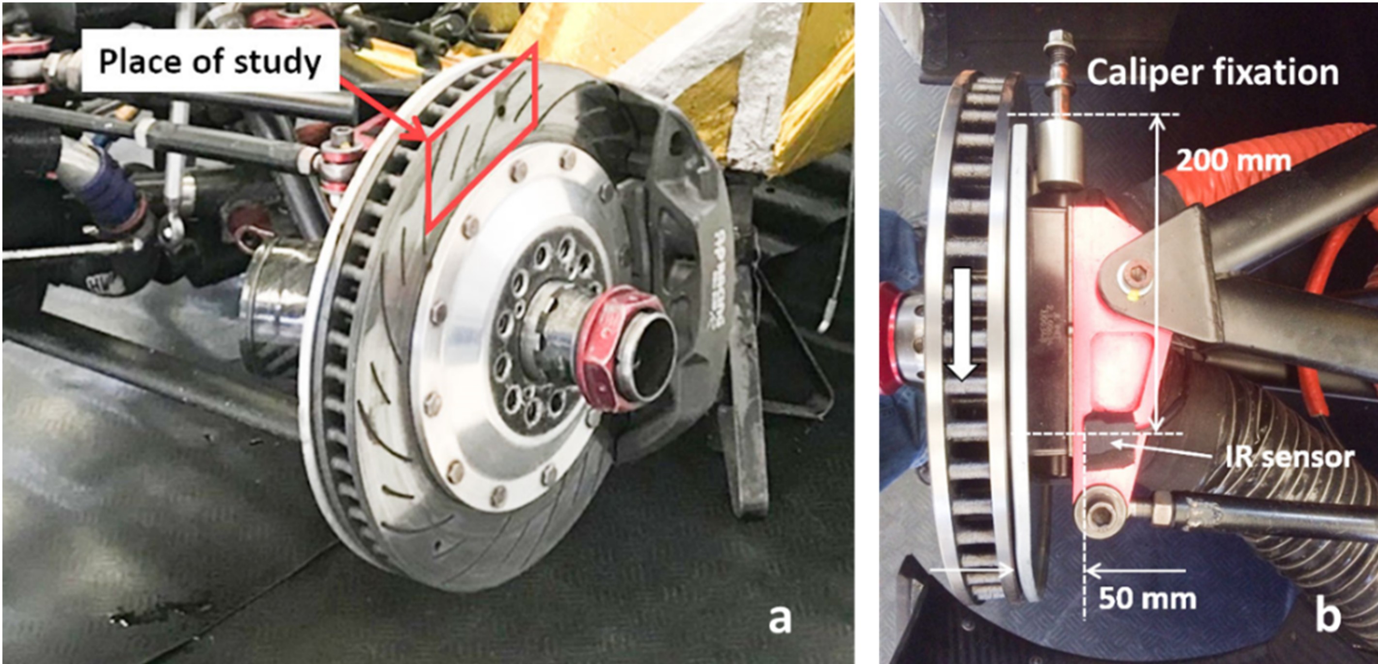
The brake disc sample analyzed is made of GCI, which was used in the Brazilian Stock Car Pro Series category during a weekend race at the “Autódromo Internacional José Carlos Pace – Interlagos” in São Paulo City. The circuit has 11 corners, 7 braking points being 2 in the end of high speed straight. The disc sample collected was submitted to 38 laps in total, approximately 168 km. The front and rear discs were manufactured by Fremax, ventilated with grooves, floating type with fixed caliper. The front brake disc has a diameter of 375 mm and a 36 mm thickness. The front caliper was an AP Racing CP9665 model mounted with six distributed pistons, three in each side of the caliper, with 26.9mm diameter, 31.8mm and 38.1mm respectively. The brake device is shown in the image of Figure 1(a). The master cylinder was an AP Racing CP2623 model with a bore of 23.8mm and a stroke of 25.4mm. The pads are standard for all the teams by technical regulation and supplied by Fremax.
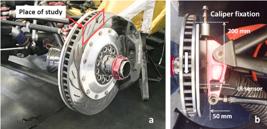
Photographs of the (a) Stock Car Pro Series front brake device and (b) Front brake IR sensor installation.
The data acquisition system used by the Stock Car Pro Series is a PI-Toolbox real-time telemetry made by Cosworth in UK. An Infrared sensor fixed at the Ackermann arm as showed in the image of Figure 1(b), collecting the brake disc temperature at a frequency of 60 Hz. The IR sensor is positioned on the Ackermann arm at 50 mm from the disc and 200 mm from the boundary edge of the pad contact surface. A drift in the temperature collected is expected due to the sensor distance from the disc and from the pad.
3.2. Methods
Samples for analysis of microstructural properties were taken by cross sectioning the working surface of the disc. The samples were analyzed by optical microscope and Scanning Electron Microscopy (SEM - Jeol JSM-6510) in the laboratories of Mackenzie Presbyterian University. For scanning microscopy, those samples were polished and etched with 2% nital by volume. To confirm the silicon contend of the sample, an optical emission spectrometer GNR S5 SOLARIS CCD Plus (S5 SCP) was used, and the analysis was carried out by the Jandinox Industry laboratory. The floating type of ventilated brake disc was fabricated with grey cast iron, using casting process with sand mold and machined before drilling for weight calibration. By means of grading on the micrograph, it can be assessed that there was no change in the percentage of graphite in the disc core in comparison with the base line.
In addition, a hardness measurement of the disc-working surface using a micro hardness Zwick/Roell Emco-Test device was carried out in both samples, brand new and used disc, to evaluate meaningful changes in material hardness behavior under thermal stress environment. Because of ruff end surface finishing, the brand-new disc sample presented a wide variability in the hardness measurements data. For that reason, the authors decided to provide a pre surface polishing before carrying out new set of hardness measurements. The device was set to apply 100 mg of load at random points of the working surface of both samples. Ten measurements on each sample were taken to provide statistical confidence of results with 95% of data significance.
3.3. Material
As the brake disc manufacturer did not supply a material specification, an analysis of the chemical compositions of the brake disc studied was carried out using an EDS - Energy Dispersive Spectroscopy of X-Ray. This alloy chemistry is summarized in Table 1 and presents a typical alloy used for brake discs. The GCI presents an effective thermal diffusivity as one of the most important properties of materials to use for brake disc application. This property is directly influenced by the Carbon Equivalent (CE) content in the alloy16-18.
Calibration in the internal standard mode using a C2425 sampler (ductile iron) from the National Institute of Standards and Technology Standard Reference Material (NIST SRM) (Gaithersburg, MD, USA), the silicon composition measured by EDS was confirmed to be approximately 1.84% by weight of Si and 0.54% by weight of Mn by optical emission spectroscopy.
4. Results and Discussion
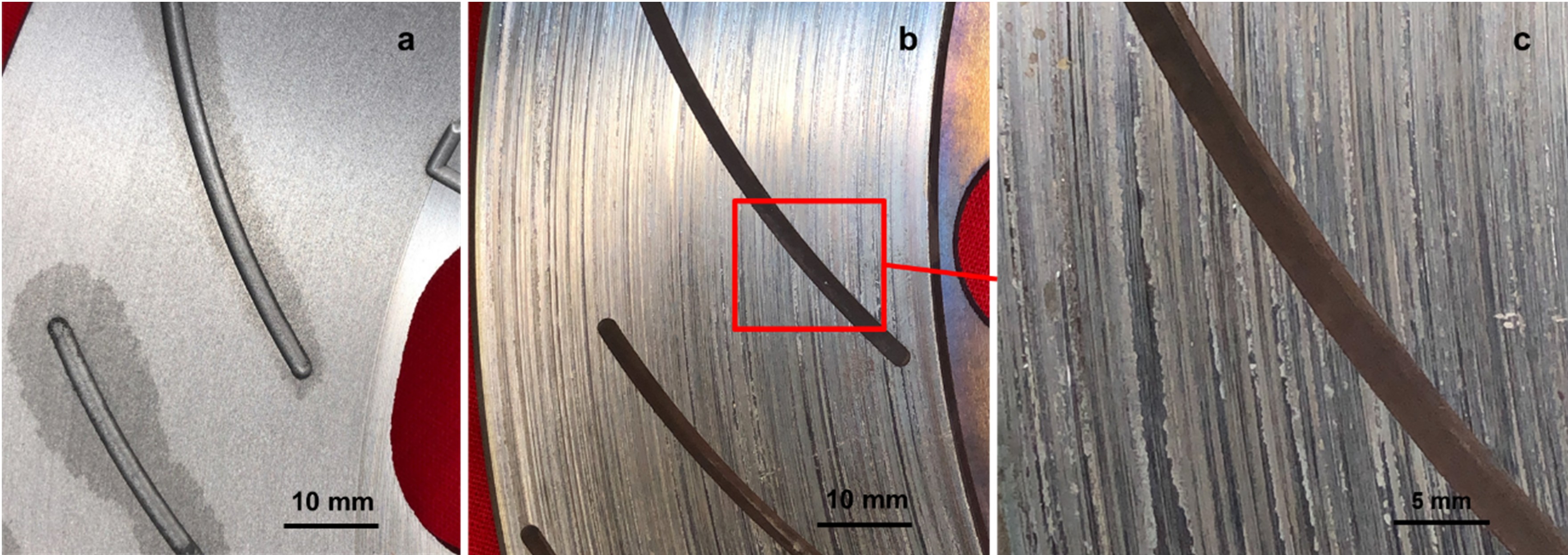
The images presented at Figure 2 illustrate a base line sample of the (a) brand new brake disc compared with the (b) used after the race event. Images (b) and (c) show the surface wear of the brake disc after use, highlighting characteristic marks that indicate the action of mechanical stresses during service.. The disc sample shown a catastrophic wear due to abrasion, adhesion, as well as material transfer between the brake disc and the pads as shown in Figure 2(c).
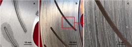
Photographs of (a) a new brake disc, (b) a used brake disc after 38 laps (168 km), and (c) a detail of abrasive wear on the used brake disc.
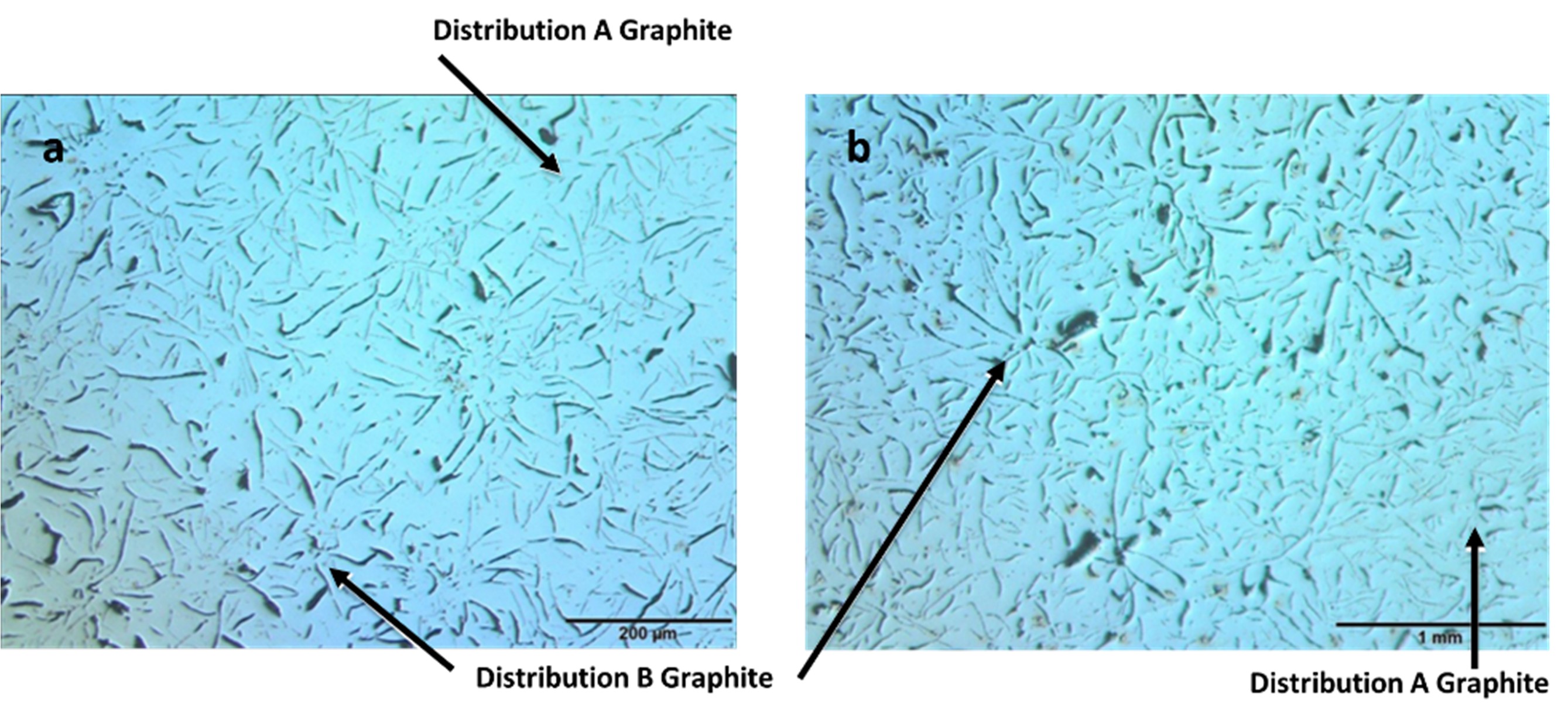
Micrographs of the cross-section of the central core of the discs are shown in Figure 3. The graphite type classification in the GCI brake disc samples are essentially A and B for (a) new brake disk and (b) used brake disc samples, as expected for the material application. Collini et al10 mention in their work that type A lamellar graphite presents random orientation and is preferred for most applications. A microstructure consists of graphite flakes surrounded by pearlite also are found by Wang et al19 in similar GCI.

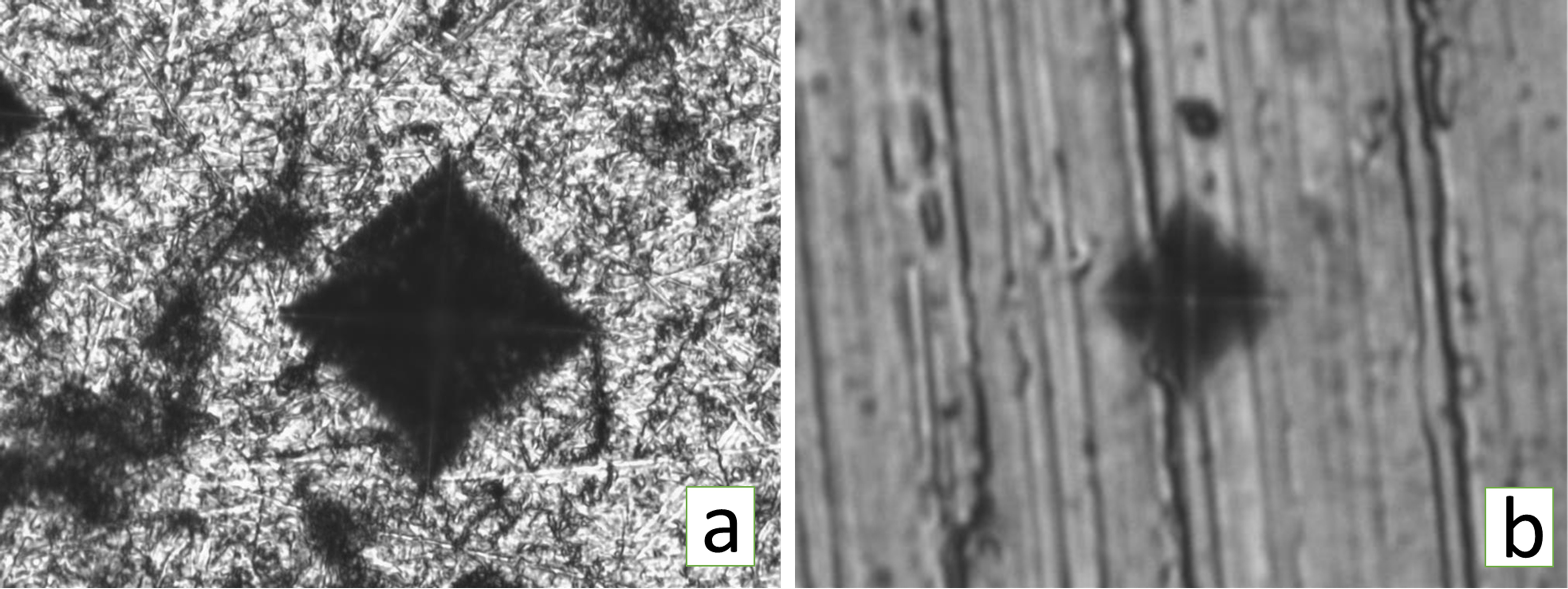
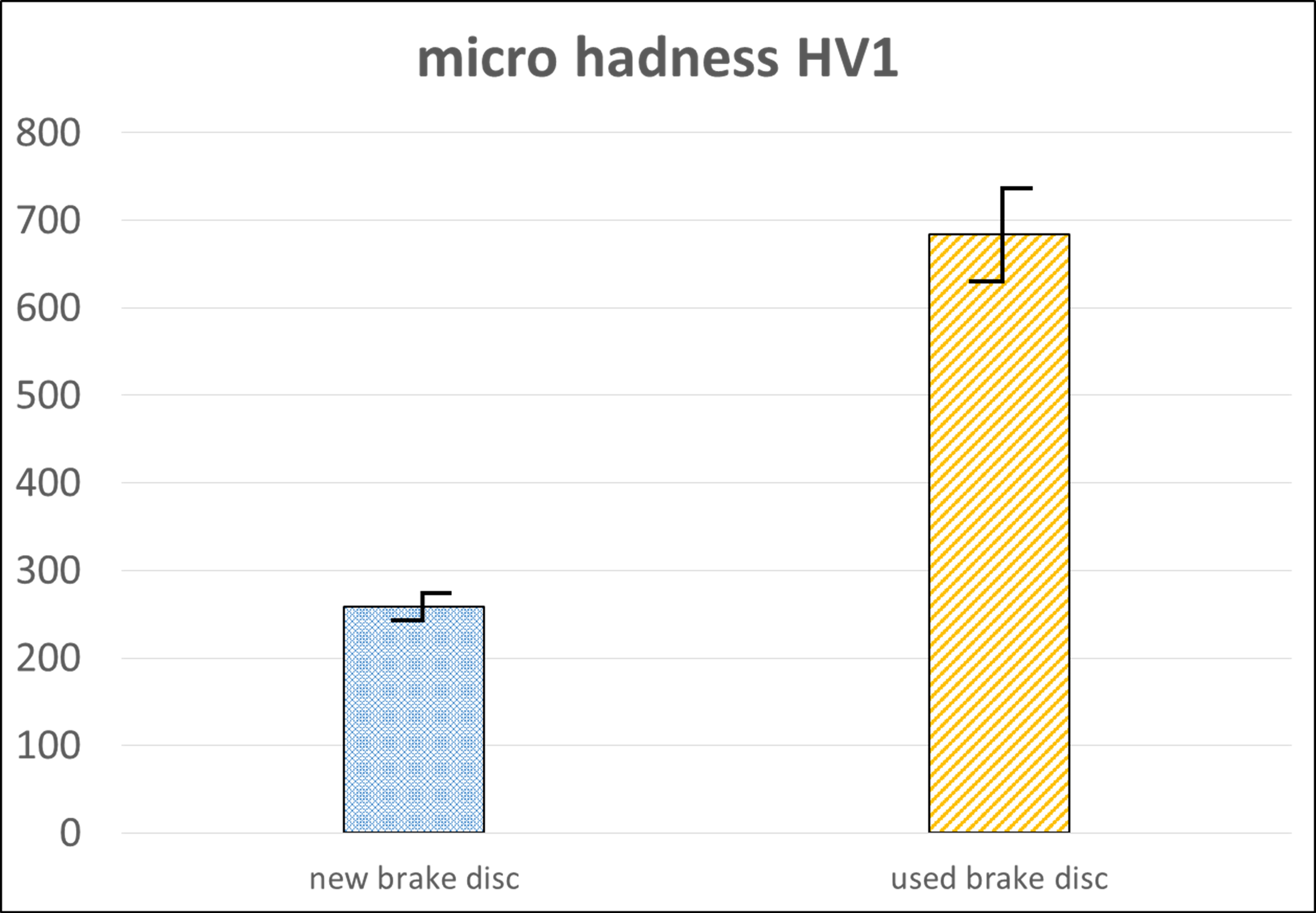
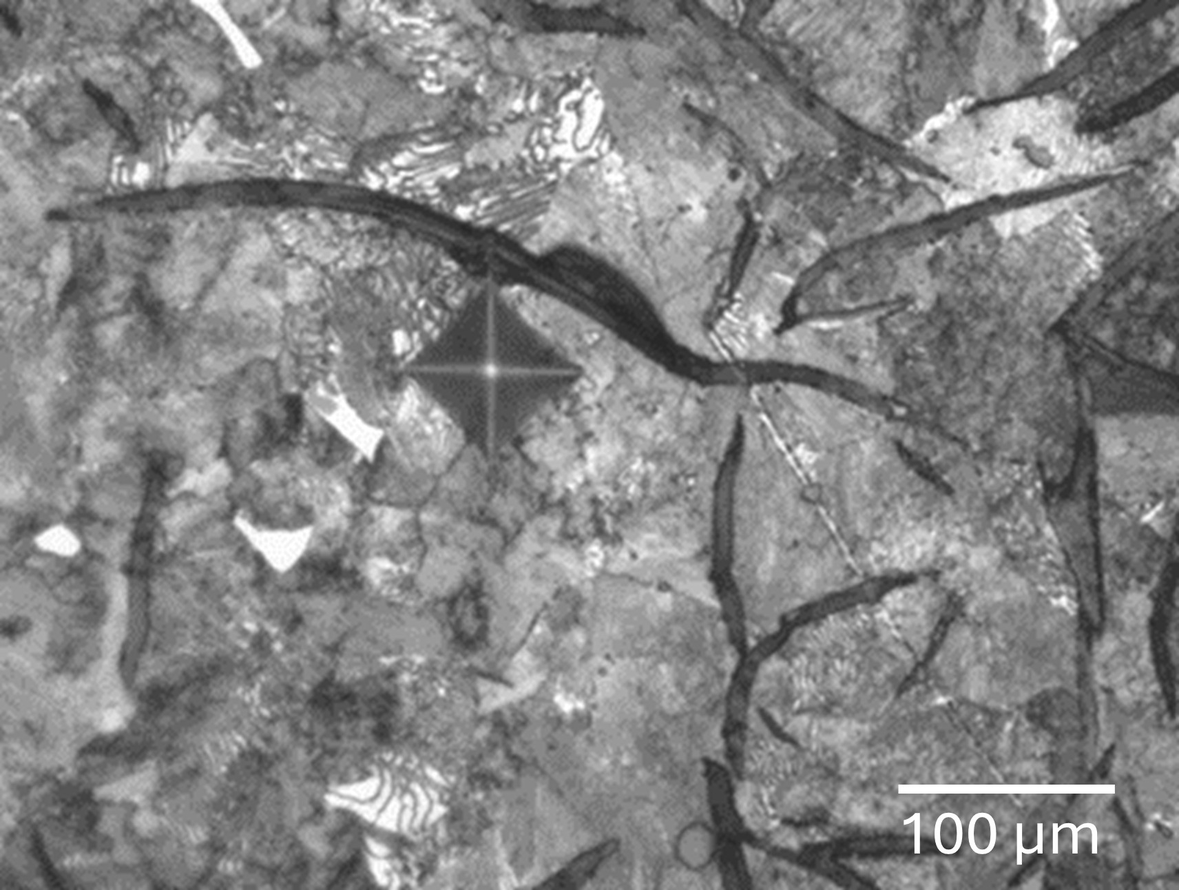
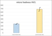
The images presented in Figure 4 show hardness impression of the (a) brand new disc working surface and (b) used disc working surface. A graph of comparison results is presented at Figure 5. The hardness measured of the working surface of the brand-new disc presented an average of 259 HV with a standard deviation of 27 HV compared with 685 HV with a standard deviation of 86 HV from the used disc in the correspondent region. In addition, a significance difference between the hardness of working surface of the brand-new disc and the thermally affected zone from the used one was noticed. The substantial increase in surface hardness from the used brake disc compared with the brand-new disc corroborates to surface phase transformation due to thermal and friction stress. Sathish et al.20 state that heat-induced changes in the surface microstructure and structural phase transformation of the brake disc material significantly impact micro-cracks formation. Complementary, ten hardness measurements in the phase transformation zone were also carried out on the micrograph sample that presented a hardness average of 319 HV as shown in the image of Figure 6.
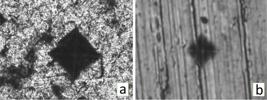
Photographs of hardness impressions on the working surface of (a) a new disc sample and (b) a used disc sample after 38 laps (168 km).
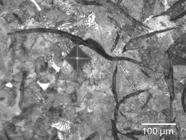
Micrograph of hardness impression in the phase transformation zone of the used disc sample.
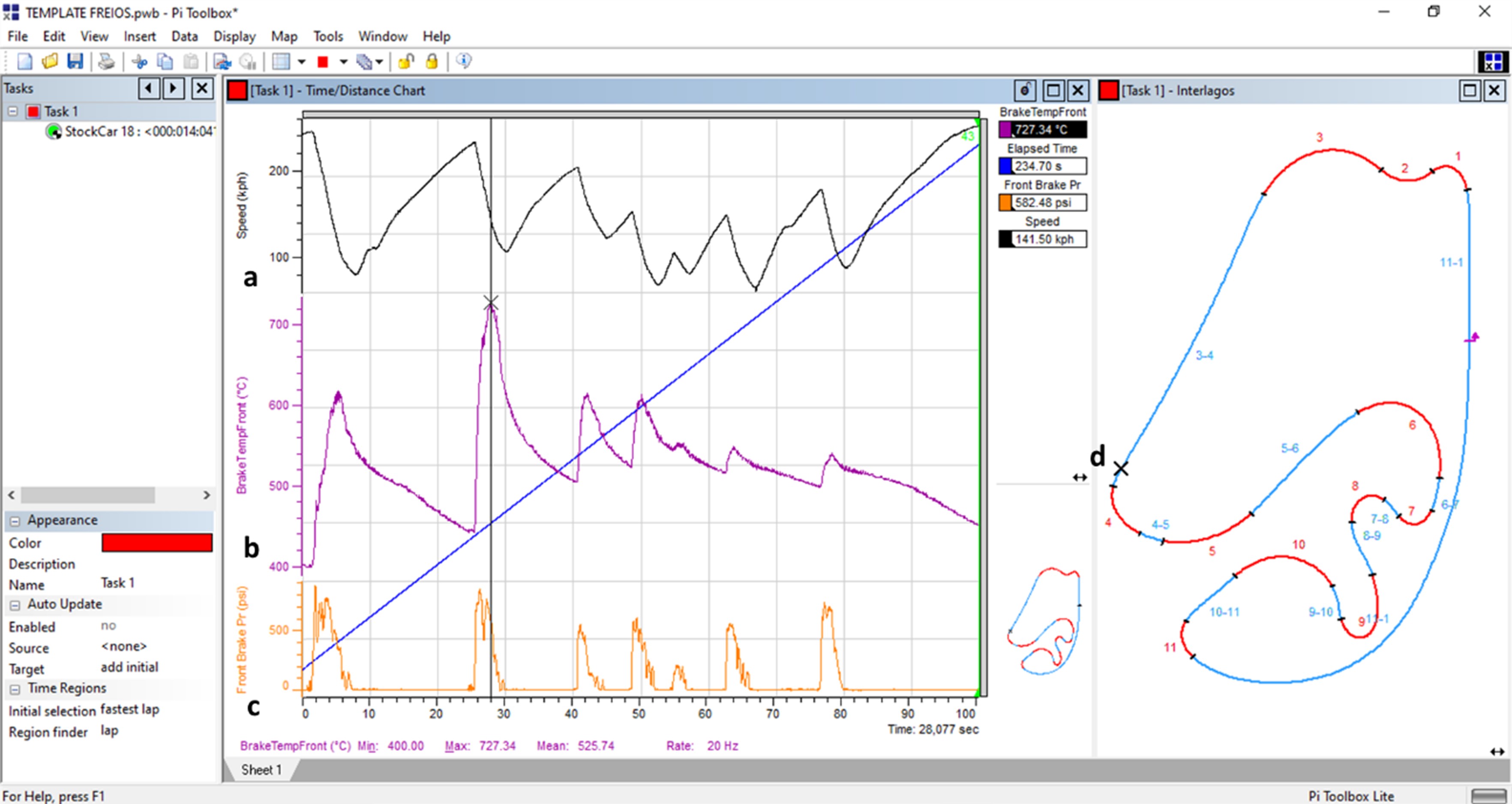
The image presented in Figure 7 shows telemetry data of the car: speed, front brake temperature, master cylinder pressure over time histogram, during the fastest lap of the car number 18 at Interlagos racing circuit during a race event. The zone of brake disc temperature collected represents actual working surface studied.
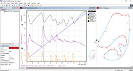
Telemetry data of Stock Car no. 18 during the race: (a) car speed, (b) front brake disc temperature, (c) master cylinder pressure, and (d) GPS position on the circuit corresponding to the peak brake disc temperature during the fastest lap.
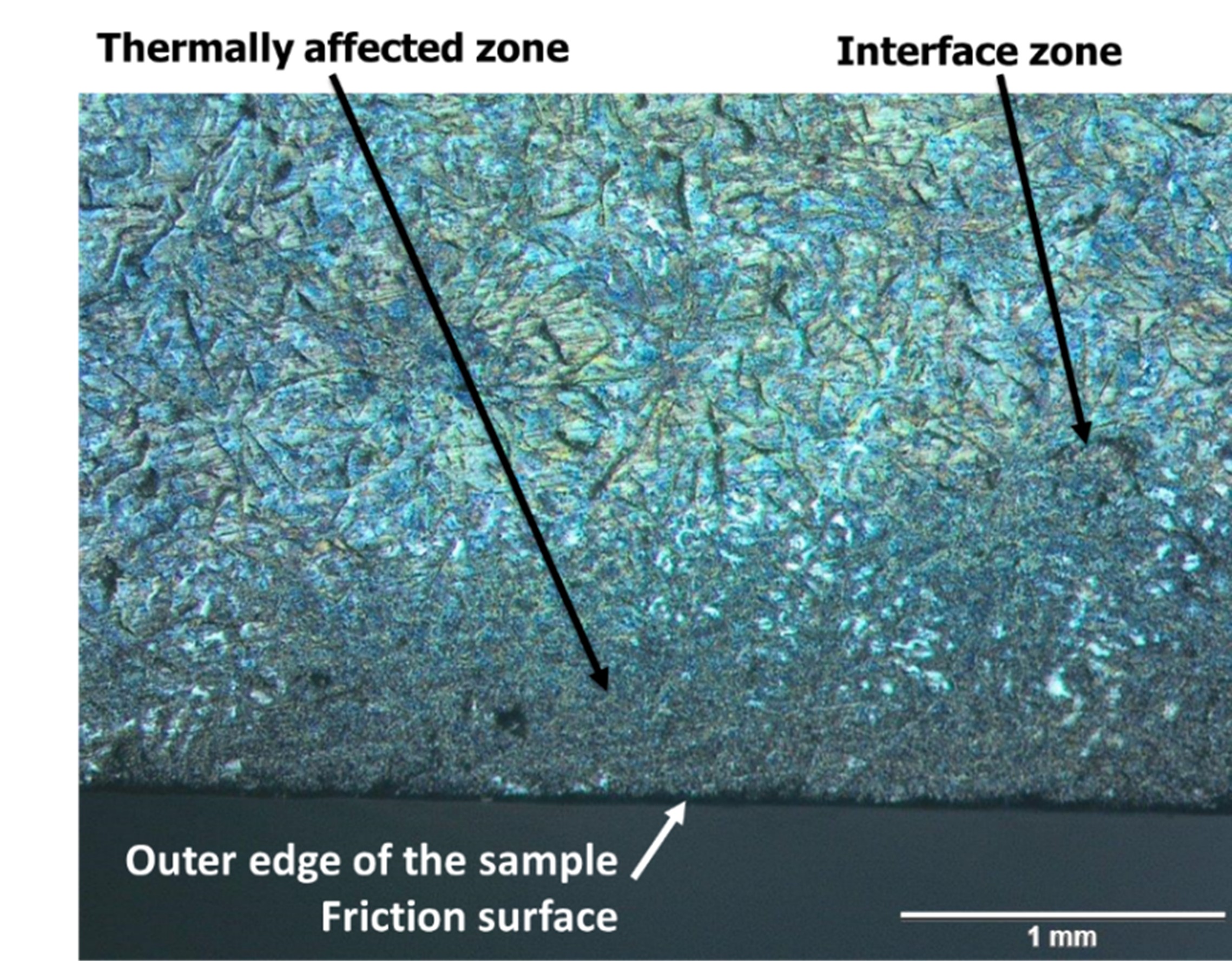
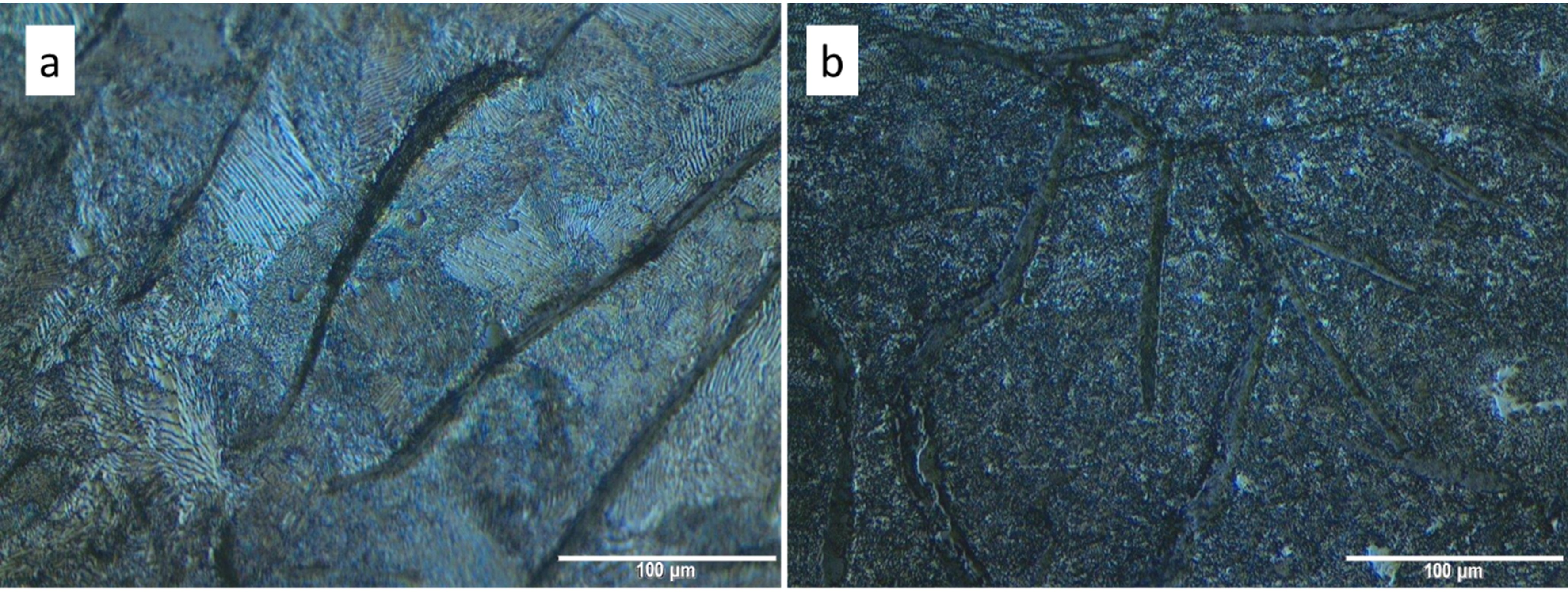
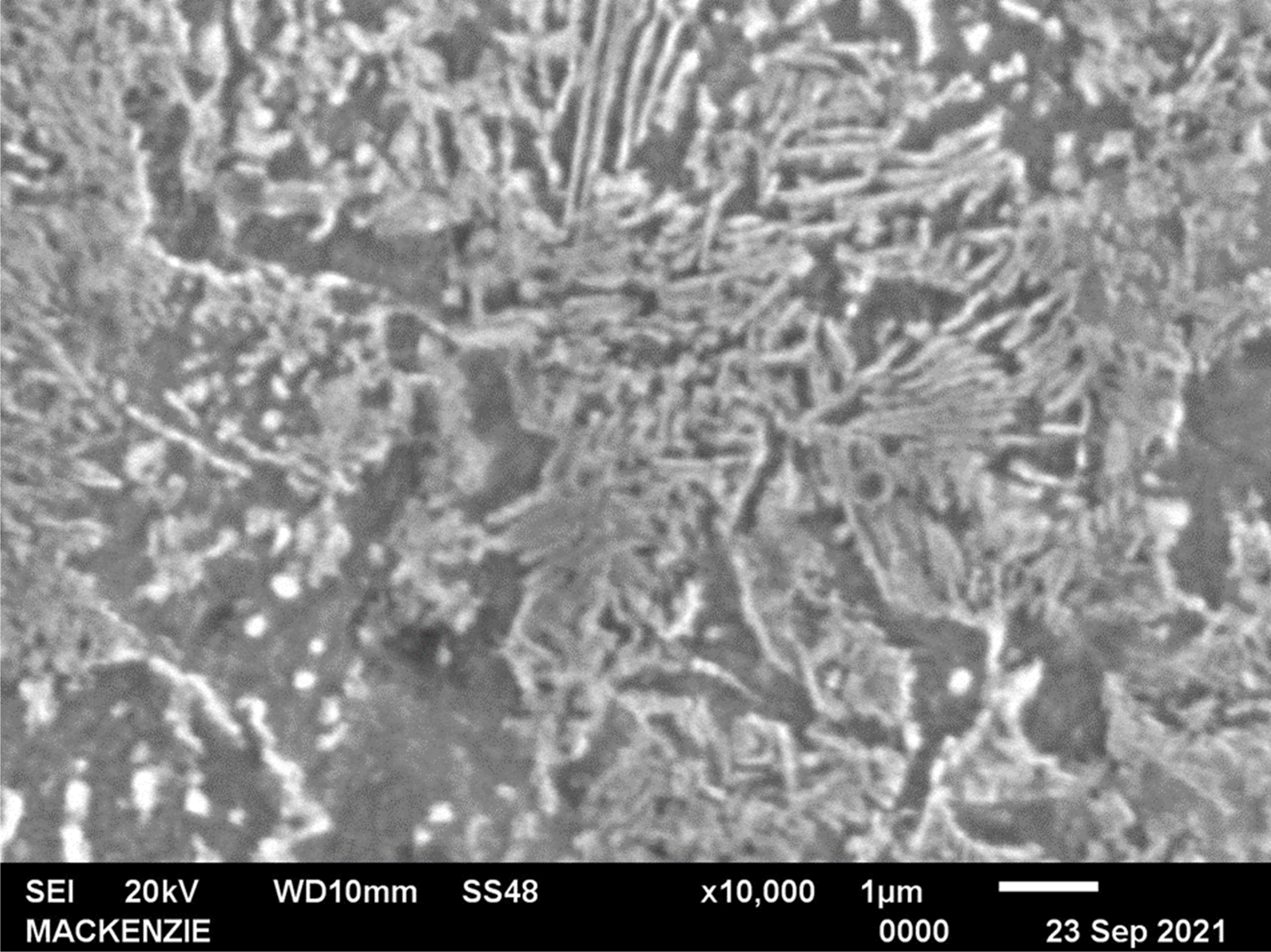
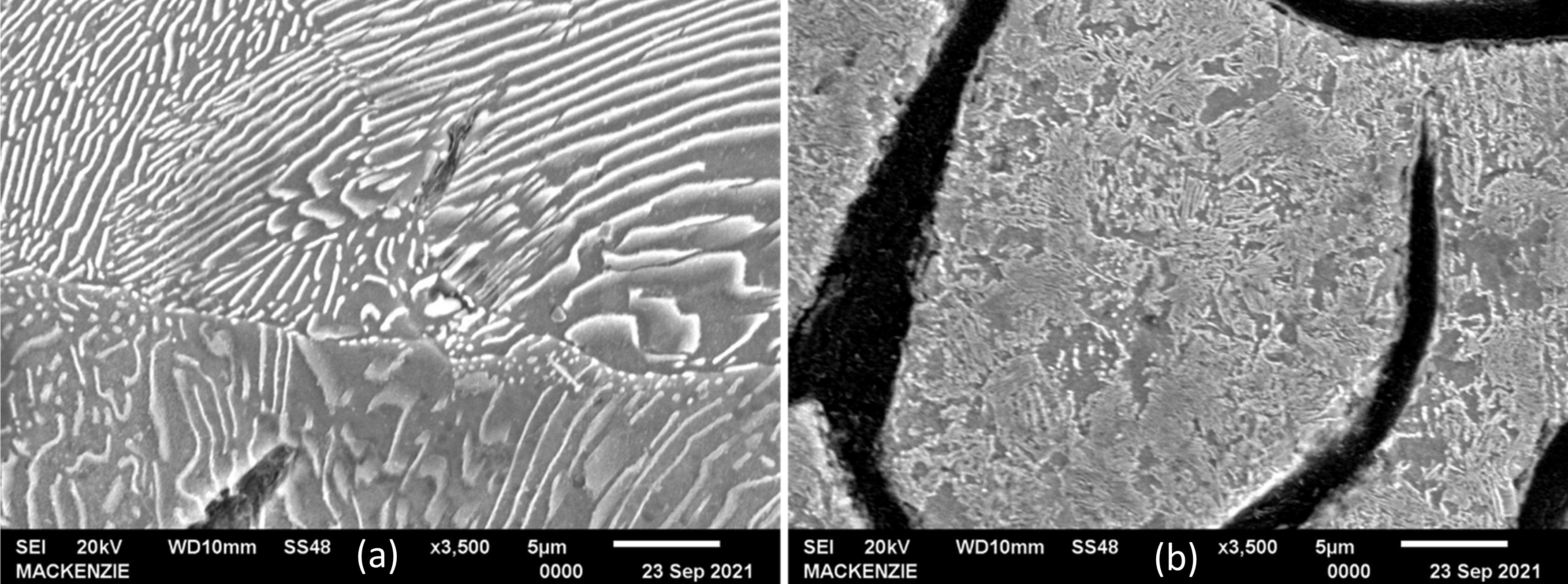
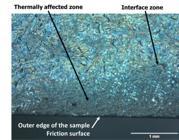
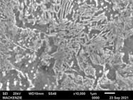
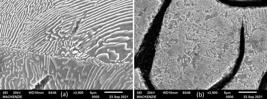
The telemetry from the front brake disc presented a variation of brake disc temperature during a lap on the hardest brake application from 440 °C up to 727 °C in a very short period of time, 2.6 seconds and post cooling to 500 °C in less than 13 seconds. It is important to notice that as discussed on case background, a 5 to 7% drift in the temperature collected is expected due to the sensor distance from brake disc and from the pad. Despite any possible drift on brake disc temperature collected by the telemetry, the evidence shown by the micrograph, that the brake disc peak temperature was enough to promote austenitization of the disc material as shown in Figures 8 and 9. The main characteristics of this zones are the size and lamellar space. It is possible to see that in outer diameter was promoted an ultra-fine perlite layer what is named of thermally affected zone (Figure 9). The Figures 10(a) and (b) shows in detail the area which occurred the perlite refinement. It was difficult to identify this ultra-fine perlite by optical microscopy, so the samples were submitted to MEV analyses observed in Figures 11 and 12.
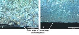
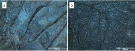
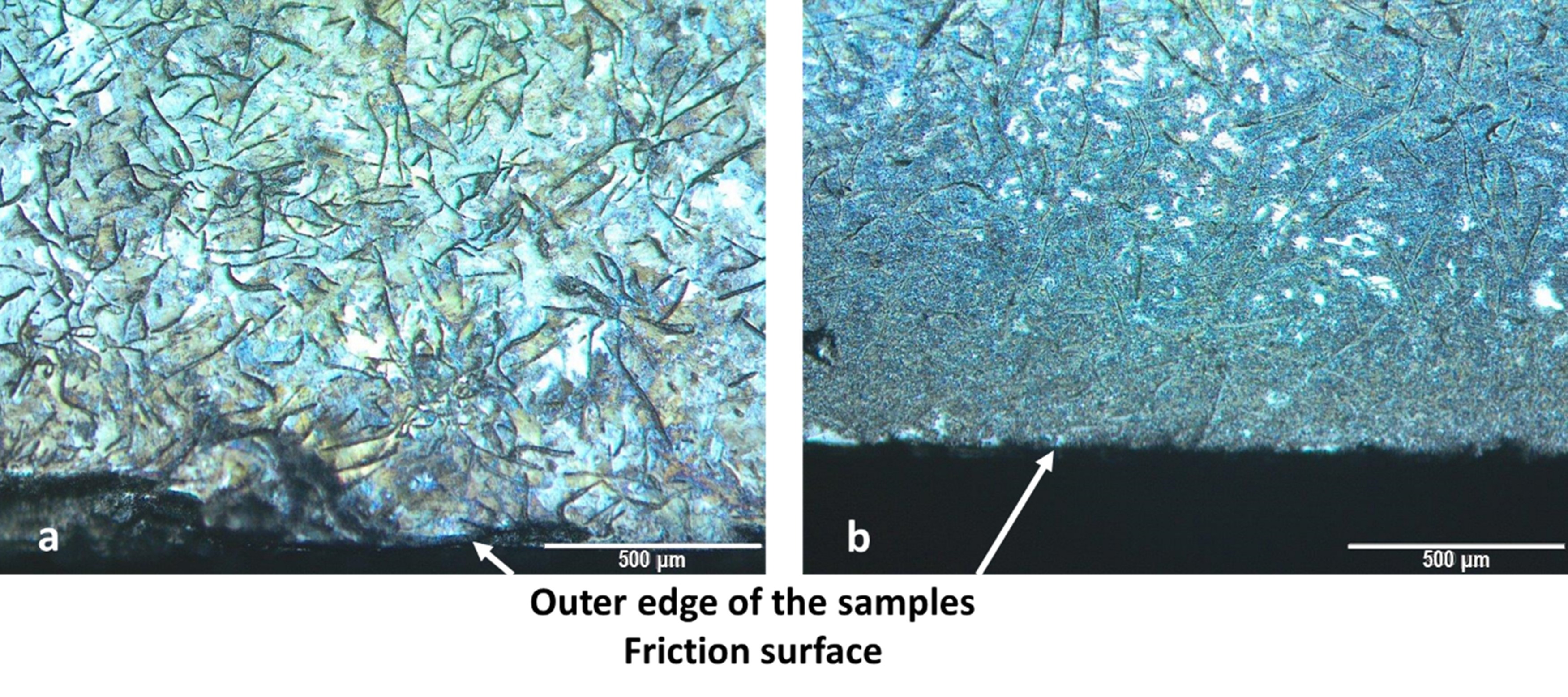
Optical micrographs of (a) the center and (b) the thermally affected zone of the used brake disc sample.
Lap telemetry data is presented in Table 2 to illustrate critical parameters regarding its minimum and maximum values during the hardest brake circumstance right before the driver took the corner called “lago” in the end of the straight called “oposta” as shown in Figure 7(d) during his fastest lap in the race. As can be determined, the heating rate reached approximately 109 °C per second and the cooling rate -17,5 °C per second.
Telemetry data from PI-Toolbox during the fastest lap from Stock Car #18 at Interlagos racetrack.
External stresses were estimated from telemetry data during braking tests, specifically from the pressure sensor installed in the front master cylinder. Using the measured pad load (1654 kgf), the normal stress was calculated and estimated the bending and tensile stresses based on simplified disc geometry. A uniaxial stress analysis was conducted considering the lever arm and load application point, allowing us to estimate the total mechanical stress at the surface and inner region of the disc. Internal stresses were inferred from residual deformation after sectioning the discs. When cutting the used disc, a gap of 4.2 mm, suggesting the presence of residual tensile stress generated by thermal gradients during braking cycles. In contrast, the cut on the new disc showed material contraction (compression), serving as a control reference.
A thermally affected zone can be seen on the outer edge of the brake disc, as shown in Figure 8. A clear phase transformation on the used brake disc sample, in Figure 8(b), can be identified comparatively with the same new brake disc sample, Figure 8 (a), outer region. It was also able to estimate that the affected zone reached a depth of 1 mm from the working surface as shown in Figure 9 with the same used brake disc sample micrograph.
The Figure 10(b) compared with (a) shows that the graphite has not changed its distribution or morphology in the thermally affected zone. Finally, it can be seen by SEM, the spacing between the pearlite lamellae found inside the sample in the thermally affected zone on the working surface of the disc as showed in Figure 11. In this image, it is possible to visually observe regions where the spacing between consecutive lamellae (distance between centers of white lamellae) appears to be between 5 and 10 lamellae per µm, which results in estimated lamellar spacings between 50 and 100 nm, evidencing the presence of nanoperlite.
As can be seen in the Figure 12, the thermal cycle imposed during the drastic speed reduction may have reached temperatures sufficient for the austenitization of the working surface of the disc. The subsequent rapid cooling favored of pearlite with reduced interlamellar spacing. The transformation of ferrite (α phase, CCC) into austenite (γ phase,CFC) involves a change in the crystal structure and specific volume, due to the difference in the atomic packing factors between the two phases. This process induces local volumetric variations during heating and cooling, which can generate residual internal stresses in the microstructure. These stresses, accumulated cyclically during use, can act as stress concentration points and contribute to the nucleation and propagation of thermal fatigue cracks in the surface region of the disc.. The working surface of the disc reaches austenitization temperature, 38 times during the racing and 114 times above 600°C in a time span of just over 1 hour.
5. Conclusions
This article aimed to investigate the microstructural changes that occurred in racing brake discs after a Stock Car Pro Series race as one of the possible causes to lead the pearlitic GCI component to present catastrophic wear and consequently fail in real racing condition.
The following conclusions can be drawn:
• Disc breakage was primarily associated with intense abrasive and adhesive wear, compounded by localized thermal and mechanical loading during racing.
• The outer edge of the disc surface exhibited a refined pearlitic microstructure, identified as nanoperlite. This refinement is attributed to thermal gradients and plastic deformation.The presence of nanoperlite indicates that high surface temperatures and deformation happened locally during braking, although austenitization was probably incomplete or limited to very thin surface areas, which may explain differences between measured temperatures and microstructural observations.The overall pearlitic matrix and graphite morphology within the brake disc were not significantly altered in the bulk material, suggesting that the microstructural changes were confined to surface-adjacent regions exposed to extreme conditions.
6. Acknowledgements
The Authors would like to thank Blau Motorsport Stock Car Pro Series Team for their valuable partnership on this work, carrying out track tests, supplying real conditions brake components as well as estimable field data.
-
Data Availability
The dataset supporting the findings of this study is not publicly available, as no research data were generated or analyzed beyond those presented in the manuscript.
7. References
-
1 Romagnuolo F, Avolio S, Fichera G, Ruffini M, Stefanelli R, Timpone F. A co-simulation platform with tire and brake thermal model for the analysis and reproduction of blanking. Vehicles. 2023;5(4):1605-21. http://doi.org/10.3390/vehicles5040087
» http://doi.org/10.3390/vehicles5040087 -
2 Zhang Q, Liu H, He Z, Mo J, Jin W, Shen M, et al. Impact of initial braking temperature on thermal-induced brake fade during long-downhill operations. Eng Fail Anal. 2025;167:109077. http://doi.org/10.1016/j.engfailanal.2024.109077
» http://doi.org/10.1016/j.engfailanal.2024.109077 - 3 Guesser WL, Baumer I, Tschiptschin AP, Cueva G, Sinatora A. Ferros fundidos empregados para discos e tambores de freio. In: Brake Colloquium SAE Brazil; 2003; Gramado. São Paulo: SAE; 2003.
- 4 Gowtham S, Manas MB. Elimination of brake fade in vehicles by altering the brake disc size (a concept). Int J Innov Res Sci Eng Technol. 2015;4(11): 11349-52.
-
5 Bakshi S, Leiro A, Prakash B, Bhadeshia HKDH. Dry rolling/sliding wear of nanostructured pearlite. Mater Sci Technol. 2015;31(14):1735-44. http://doi.org/10.1179/1743284714Y.0000000751
» http://doi.org/10.1179/1743284714Y.0000000751 -
6 Stodolny J, Gołaszewski A, Łotarewicz A. Fragmentation rate of cementite lamellas in nanopearlite. J Miner Met Mater Soc. 2019;71(9):3298-304. http://doi.org/10.1007/s11837-019-03655-w
» http://doi.org/10.1007/s11837-019-03655-w - 7 Wang K, Bai T, Xu J, Zhu H, Qian Y, Wang X, et al. Investigation into the mechanisms of Corrosion-Induced rolling contact fatigue crack initiation and propagation in pearlitic rails. Eng Fail Anal. 2024;163(Part B):108614. http://doi.org/10.1016/j.engfailanal.2024.108614.
-
8 Wang K, Yang J, Tian C, Xu J, Bai T, Gao W, et al. Study on gradient microstructural characteristics and crack propagation mechanisms in plasma-quenched rails and white etching layer containing rails. Tribol Int. 2025;211:110864. http://doi.org/10.1016/j.triboint.2025.110864
» http://doi.org/10.1016/j.triboint.2025.110864 - 9 ASTM: American Society for Testing and Materials. ASTM A247-19: standard test method for evaluating the microstructure of graphite in iron castings. West Conshohocken: ASTM International; 2019.
-
10 Collini L, Nicoletto G, Konečná R. Microstructure and mechanical properties of pearlitic gray cast iron. Mater Sci Eng A. 2008;488(2):529-39. http://doi.org/10.1016/j.msea.2007.11.070
» http://doi.org/10.1016/j.msea.2007.11.070 -
11 Reis BCM, dos Santos AJ, Pereira NFS, do Carmo DJ, de Faria GL, Câmara MA, et al. Effect of Nb addition on the machinability of a pearlitic gray cast iron. J Mater Eng Perform. 2022;31(7):5983-99. http://doi.org/10.1007/s11665-022-06669-9
» http://doi.org/10.1007/s11665-022-06669-9 -
12 Xu J, Liu Y, Zhou S. Calculation models of interlamellar spacing of pearlite in high-speed 82B rod. J Iron Steel Res Int. 2008;15(4):57-60. http://doi.org/10.1016/S1006-706X(08)60144-2
» http://doi.org/10.1016/S1006-706X(08)60144-2 -
13 Djafri M, Bouchetara M, Busch C, Khatir S, Khatir T, Weber S, et al. Influence of thermal fatigue on the wear behavior of brake discs sliding against organic and semimetallic friction materials. Tribol Trans. 2018;61(5):861-8. http://doi.org/10.1080/10402004.2018.1437491
» http://doi.org/10.1080/10402004.2018.1437491 -
14 Aranke O, Algenaid W, Awe S, Joshi S. Coatings for automotive gray cast iron brake discs: a review. Coatings. 2019;9(9):552. http://doi.org/10.3390/coatings9090552
» http://doi.org/10.3390/coatings9090552 -
15 Bendikiene R, Ciuplys A, Cesnavicius R, Jutas A, Bahdanovich A, Marmysh D, et al. Influence of austempering temperatures on the microstructure and mechanical properties of austempered ductile cast iron. Metals. 2021;11(6):967. http://doi.org/10.3390/met11060967
» http://doi.org/10.3390/met11060967 -
16 Maluf O, Angeloni M, Castro DBV, Bose Filho WW, Spinelli D, Ruckert COFT. Effect of alloying elements on thermal diffusivity of gray cast iron used in automotive brake disks. J Mater Eng Perform. 2009;18(7):980-4. http://doi.org/10.1007/s11665-008-9326-1
» http://doi.org/10.1007/s11665-008-9326-1 -
17 Hecht RL, Dinwiddie RB, Wang H. The effect of graphite flake morphology on the thermal diffusivity of gray cast irons used for automotive brake discs. J Mater Sci. 1999;34(19):4775-81. http://doi.org/10.1023/A:1004643322951
» http://doi.org/10.1023/A:1004643322951 -
18 Gao CH, Huang JM, Lin XZ, Tang XS. Stress analysis of thermal fatigue fracture of brake disks based on thermomechanical coupling. J Tribol. 2007;129(3):536-43. http://doi.org/10.1115/1.2736437
» http://doi.org/10.1115/1.2736437 -
19 Wang B, Pan Y, Liu Y, Lyu N, Barber GC, Wang R, et al. Effects of quench-tempering and laser hardening treatment on wear resistance of gray cast iron. J Mater Res Technol. 2020;9(4):8163-71. http://doi.org/10.1016/j.jmrt.2020.05.006
» http://doi.org/10.1016/j.jmrt.2020.05.006 -
20 Sathish KT, Maniraj J, Thangarasu VS. Study of friction, wear and plastic deformation of automotive brake disc subjected to thermo-mechanical fatigue. Materia. 2023;28(1):e20220329. http://doi.org/10.1590/1517-7076-rmat-2022-0329
» http://doi.org/10.1590/1517-7076-rmat-2022-0329
Edited by
-
Associate Editor:
Hamilton Abreu.
-
Editor-in-Chief:
Luiz Antonio Pessan.
The dataset supporting the findings of this study is not publicly available, as no research data were generated or analyzed beyond those presented in the manuscript.