Evaluation of Copper Diffusion Bonding Parameters Applied to the Manufacture of Flat Heat Pipes
Abstract
Flat heat pipes are highly effective for electronic thermal management, combining compact design with efficient heat transfer. Diffusion bonding is a promising manufacturing method, enabling leak-tight joints without notable plastic deformation. This study examined the effects of bonding temperature and pressure on the quality of miniature copper heat pipe joints. Optical microscopy, microhardness tests, and shear strength evaluations were used for assessment. Optimal results occurred at 875°C and 7MPa. Among four temperatures and three pressures tested, 900°C and 9MPa also yielded strong joints. Bonding time was fixed at 3600s. Good joints showed shear strengths of 5.92–6.17MPa and microhardness of 45–49HV. Interfaces had small, rounded, well-distributed defects that did not impair integrity. Temperature had a greater impact than pressure on joint quality. A flat miniature loop heat pipe made under optimal conditions (875°C, 7MPa, 3600s) displayed high-quality, deformation-free bonding and transferred up to 8W before reaching its operational limit—suitable for electronics.
Keywords:
Diffusion welding; Heat pipes; Copper; Electronics; Bonding processes
1. Introduction
Heat pipes (HPs) are passive heat transfer devices that use the phase change phenomenon of a working fluid to passively transport heat from a hot source to a heat sink in an efficient way1. Heat pipes are made up of three main elements: a casing, a working fluid and a capillary structure. Also, they are divided into three regions: the evaporator, the adiabatic section and the condenser. Their operating principle is based on the temperature difference between the evaporator and the condenser. The heat from the hot source causes the liquid in the evaporator section to evaporate, generating a vapor flow towards the condenser area, driven by the pressure differences inside the device. In the condenser, the vapor condenses as it dissipates heat to the cold source, while the condensed liquid returns to the evaporator by capillary action, assisted by the capillary structure2.
The initial design of heat pipes was based on cylindrical geometries, which were easier to manufacture. However, as heat pipe technology began to be applied in fields such as electronics, the design shifted toward flat geometries to improve the coupling with the electronic components that must be cooled.
Flat heat pipes, while beneficial, pose considerable challenges in manufacturing complexity. These complexities can lead to issues like deformation, ruptures in the container and wick structure, and leakages3,4. To address these technical challenges, some research groups have explored the use of the diffusion bonding technology5-12 to improve the manufacturing process and quality of the flat devices.
Diffusion bonding is a solid-state welding technique that, unlike traditional welding processes, does not involve the formation of a melted zone at the weld interface13,14. Instead, this process creates a monolithic component through atomic diffusion between the surfaces being joined, without significant macroscopic deformation15-17. Additionally, diffusion bonding enables the complete weld of a cross-section, with or without internal geometries, in a single step. It is a highly reliable additive manufacturing technology that does not induce a thermally affected zone, even though the entire component undergoes heat treatment15-17.
Diffusion bonding typically takes place in an inert gas atmosphere or vacuum, at temperatures ranging from 50 to 80% of the melting point of the pure metal or the onset of the melting range for an alloy. The main parameters involved in the process are temperature, pressure, bonding time, and surface finishing 16,18. Temperature is directly correlated with diffusion and creep mechanisms. Pressure must provide intimate contact, deform micro-asperities during the early stages of the process, and enhance creep during the bond cycle. This technique produces components with mechanical and microstructural properties comparable to those of the base material 15,17,19,20. As a result, diffusion bonding is particularly well-suited for welding parts with complex geometries while preserving the material's original properties, which makes it an interesting technique for industries, such as nuclear, automotive, aerospace, and personal electronics15,17.
Although extensive research has been carried out on manufacturing copper heat pipes using the diffusion bonding process5-9,21-30, in most cases the bonding process is only addressed as the manufacturing route, while little or no information about the bonding parameters are presented. Also, since most research focuses on the thermohydraulic properties of the heat pipes, a further discussion on the diffusion bonding quality and its correlation with the thermomechanical parameters used are commonly lacking, evaluating the diffusion bonding success mainly via leakage test.
The diffusion bonding parameters are particularly critical for manufacturing mini heat pipes, especially since most of them are fabricated in copper due to its high thermal conductivity and chemical compatibility. Although copper is an excellent alternative for biphasic devices, its high malleability and ductility may lead to leaks and high levels of plastic deformation if the bonding parameters are insufficient or excessive, comprising their structural integrity, geometrical tolerances and internal channel. As a result, heat transfer by phase change can be interrupted, as noticed by Krambeck30.
In this context, the present research focuses on optimizing the diffusion bonding process for the manufacturing of copper mini heat pipes. For that, an experimental procedure was executed in order to understand the effects of temperature and pressure on the manufacturing of small two-phase devices. Although the bonding time is also a critical factor in the diffusion bonding process, it was maintained constant at 3600 seconds during this study to isolate the effects of both variables, temperature and pressure. The procedure consisted of diffusion bonding two electrolytic copper sheets (C11000) of 165 x 35 x 1 mm3 combining four different temperatures (825, 850, 875, and 900 °C) with three different pressures (5, 7, and 9 MPa). Followed by a sequence of tests (microhardness, roughness, shear stress and microstructural analysis) to evaluate the bond quality.
According to the experimental results, a flat loop heat pipe in miniature was manufactured with the optimized parameters via diffusion bonding of copper sheets. The loop heat pipe was thermally tested, demonstrating the effectiveness of the proposed procedure for small device fabrication.
2. Experimental Methodology
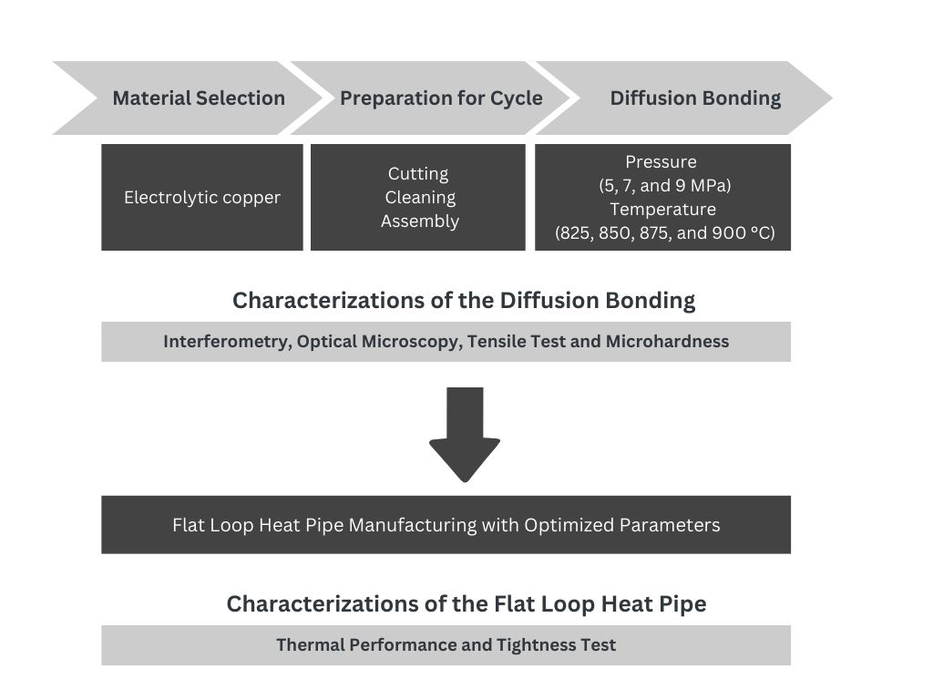
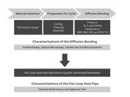
Figure 1 presents the experimental procedure used in this study, which can be divided in two major steps. The first one consists in evaluating the diffusion bonding in copper sheets, including the samples’ fabrication, the definition of parameters, and characterizations, such as surface roughness, microhardness, shear stress and microstructure. The second step consists in manufacturing a flat loop heat pipe with optimized parameters, followed by the characterization of its tightness and thermal performance.
2.1. Diffusion bonding study
2.1.1. Samples preparation
The C11000 copper was used in this work, also known as electrolytic copper, in the form of cold-rolled sheets of 1200 x 600 mm2 and 1 mm of thickness. Its nominal composition consists of 99.9% copper, with a residual percentage of oxygen and silver31,32. The C11000 was selected due to its high thermal conductivity of 394 W/mºC.
The sheets were cut via abrasive waterjet using the Flow Waterjet® M2c 2030, resulting in 48 rectangular copper plates with dimensions of 3,500 mm2 (100 x 35 mm2). After the machining, the copper sheets were cleaned with an aqueous solution of 10% sulfuric acid to remove oxides from the copper surface. Then, they were manually grounded with #220 mesh SiC sandpaper, cleaned in an ultrasonic bath with acetone for 15 minutes, and dried with a hot air blower.
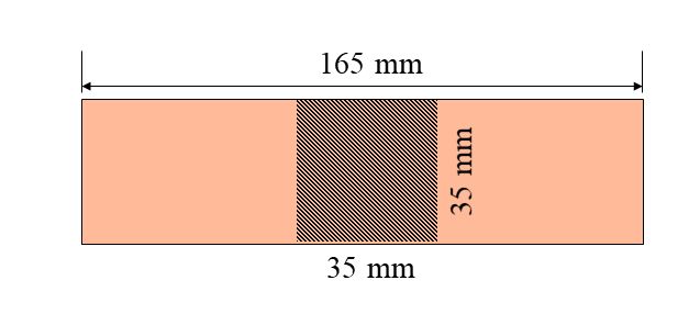
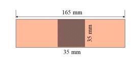
Each sample was composed of two rectangular plates, in a total of 24 specimens of 165 x 35 mm2 with an overlap dimension of 35 x 35 mm2 (contact area) for the diffusion bonding process, as can be seen in Figure 2.
2.1.2. Tested parameters
The diffusion bonding study was conducted by submitting the samples to four different temperatures (825, 850, 875, and 900 °C) in combination with three different pressures (5, 7, and 9 MPa), resulting in a total of 12 distinct manufacturing conditions (12 thermal cycles). Although the bonding time is a critical parameter in diffusion bonding, it was kept constant at 3600 seconds for all combinations in this study to isolate and better understand the effects of pressure and temperature on heat pipe manufacturing. Additionally, two samples were joined in each cycle to assess the reproducibility of the results.
The thermal cycles were carried out in a Jung® LT1513/2009 tubular furnace at a heating rate of 10 K/min until the desired temperature was reached. The process was carried out under an inert atmosphere (95% argon and 5% hydrogen) with a flow rate of 2 l/min. The gas flow was maintained during the cooling up to 300 ºC, below this temperature the flow was interrupted and the natural cooling took place.
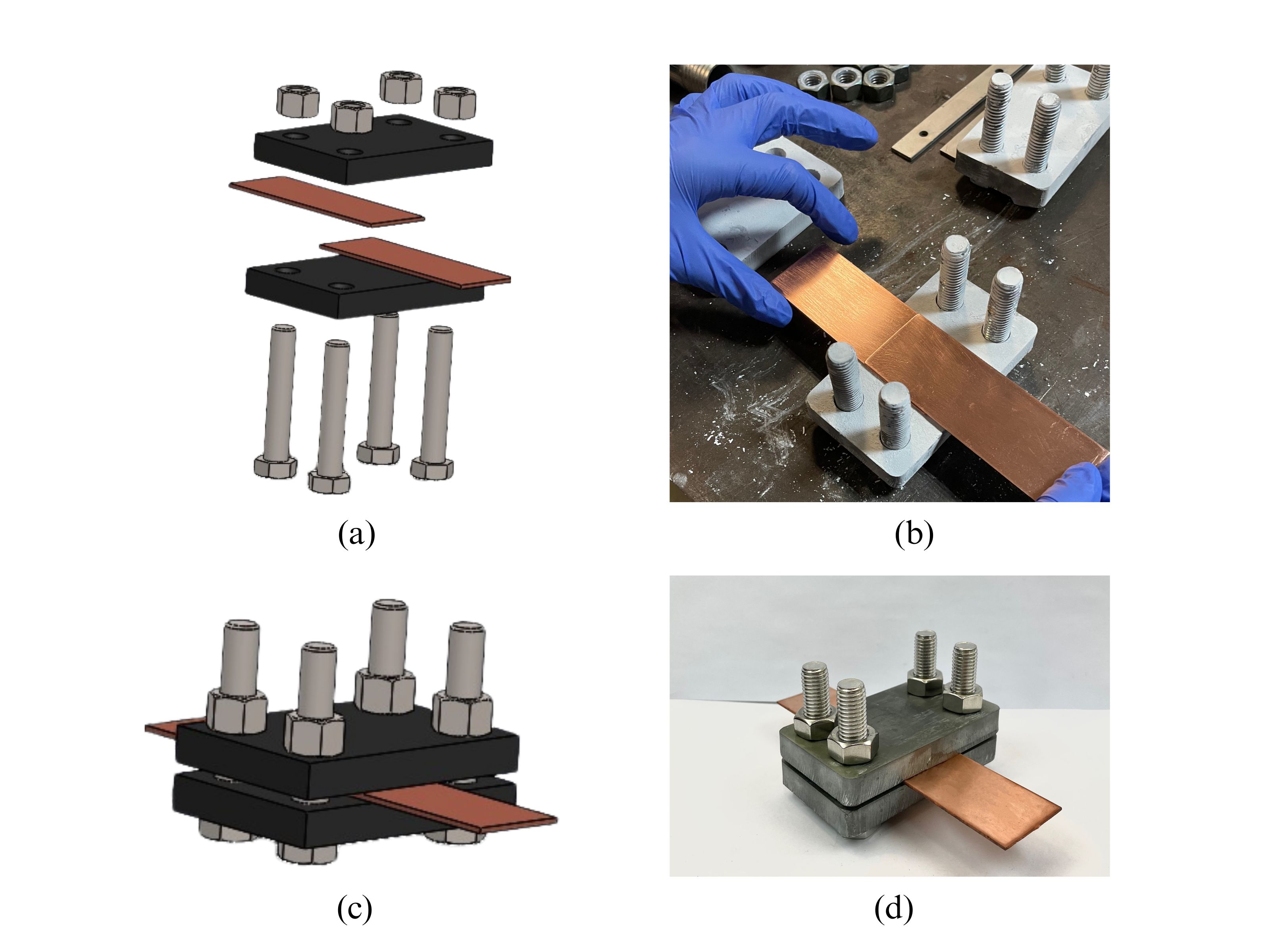
The furnace is simple and does not have an integrated system to apply pressure. For this reason, based on studies in the literature22,33, a pressure system was developed using matrix and screws, as schematized in Figure 3a. It is important to note that the system can only control pressure at room temperature. However, due to the material thermal expansion and creep at higher temperatures, the pressure is not maintained constant throughout the whole thermal cycle. However, since pressure has a greater influence in the initial stages of bonding, this variation was not addressed in the present study14. Thus, the samples were assembled inside the matrix (Figure 3b) and different pressures were applied at room temperature via a torque exerted on four screws placed in a AISI 304 stainless steel matrix (110 x 55 x 13.1 mm3), as shown in Figures 3c e 3d. The screws used were also of AISI 304 stainless steel (M12 hex).
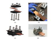
Pressure system (a) Exploded schematic view. (b) Assembly. (c) Schematic design of the final assembly. (d) Setup photo ready for the thermal cycle.
The required torque, M [Nm] was calculated according to the following equation34:
where dm is the average diameter of the screw, ψ is the friction coefficient between the screw and thread, F is the tension force, λ is the angle of the thread (60 °) and tan y can be estimated by:
where L = n.p, that n = 1 and p the step of 1.5 mm for M12 screws. Furthermore, the tension force is calculated as:
where P represents the pressure for the diffusion bonding and A is the superficial contact area.
The resulting torque values applied for each pressure condition are presented in Table1.
2.1.3. Characterizations
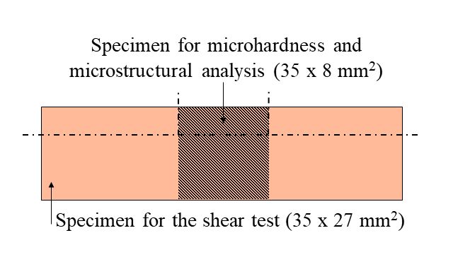
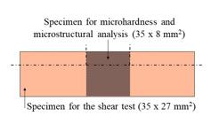
The diffusion bonded samples were characterized in terms of microhardness, surface roughness, shear stress and microstructure. Figure 4 shows specimens, after diffusion bonding, divided into two different sizes, due to area limitations of the equipment. The first one consists of 35 x 8 mm2 for the microhardness and microstructural analysis. The second one, 165 x 27 mm2 was used for the shear test.
2.1.3.1. Microhardness test
In order to assess the evolution of the microhardness of the material, Vickers microhardness tests were carried out on the samples before and after the thermal bonding cycles. For this purpose, a DIGIMESS Precision Instruments model HV-1000 was used. For each test, the samples were subjected to eight indentations under a load of 0.1 kg for 30 seconds.
2.1.3.2. Optical interferometry
A Zygo Newview 7300 series optical interferometer was used to characterize the surfaces of the sheets before bonding and after the grinding in #220 SiC sandpaper, being evaluated four distinct points. The data was processed according to the methodology proposed by a previous study35 using Mountains Map® 10 Expert software, acquiring the average roughness (Sa), root mean square deviation (Sq), maximum height value (Sz), maximum peak value (Sp) and maximum valley value (Sv) parameters, as well as the axonometric projections of the surfaces.
2.1.3.3. Shear test
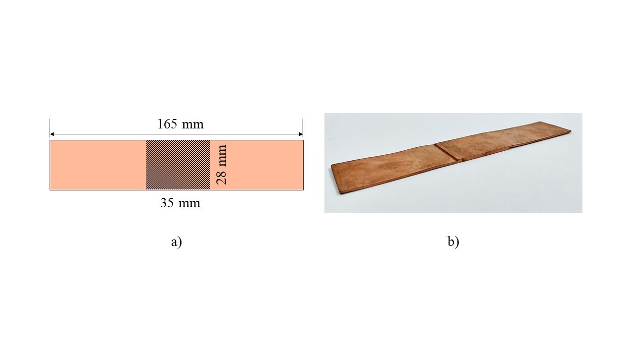
The mechanical strength of the diffusion bonded specimens was assessed using the shear test due to specimen geometry. The tests were performed on an MTS®Criterion 45 at a loading speed of 2 mm/min and at room temperature. Figure 5 shows the specimen geometry with standard dimensions of 27 x 165 mm2 and overlap dimension of 35 x 28 mm2. These specimens are in accordance with ASTM-D1002, which indicates that non-standard dimension samples can be used for development tests, as long as their dimensions are kept constant.
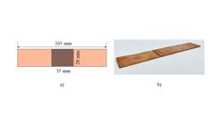
Specimen for shear testing (a) Schematic design with the dimensions (b) Diffusion bonding specimen.
2.1.3.4. Microstructural analysis
To assess the microstructural characteristics resulting from diffusion bonding, the samples were prepared and metallographically analyzed.
The samples were ground with #600, #800, #1500 and #2000 mesh SiC sandpaper, followed by polishing with a solution of 1µm alumina.
The chemical attack was carried out by immersion in pure nitric acid (65%) for 5 seconds only for the plates before thermal cycling and for the samples after thermal cycling in order to highlight the grain boundaries and allow a comparison of their size in both situations. Therefore, the micrographs of the bond interfaces of the samples after all the thermal cycles will be presented without chemical attack.
Microstructural images were captured using a MRT 50 Micron® optical microscope, focusing on the bond line to examine the bond interface and assess the defects present.
2.2. Flat loop heat pipe manufactured by diffusion bonding
To verify the results obtained in the diffusion bonding study, the optimized parameters (temperature and pressure) were used to manufacture a flat Loop Heat Pipe (LHP). The same procedure previously explained was used, consisting of applying pressure by a stainless steel matrix and screws and the set was introduced in the Jung® LT1513/2009 tubular furnace.
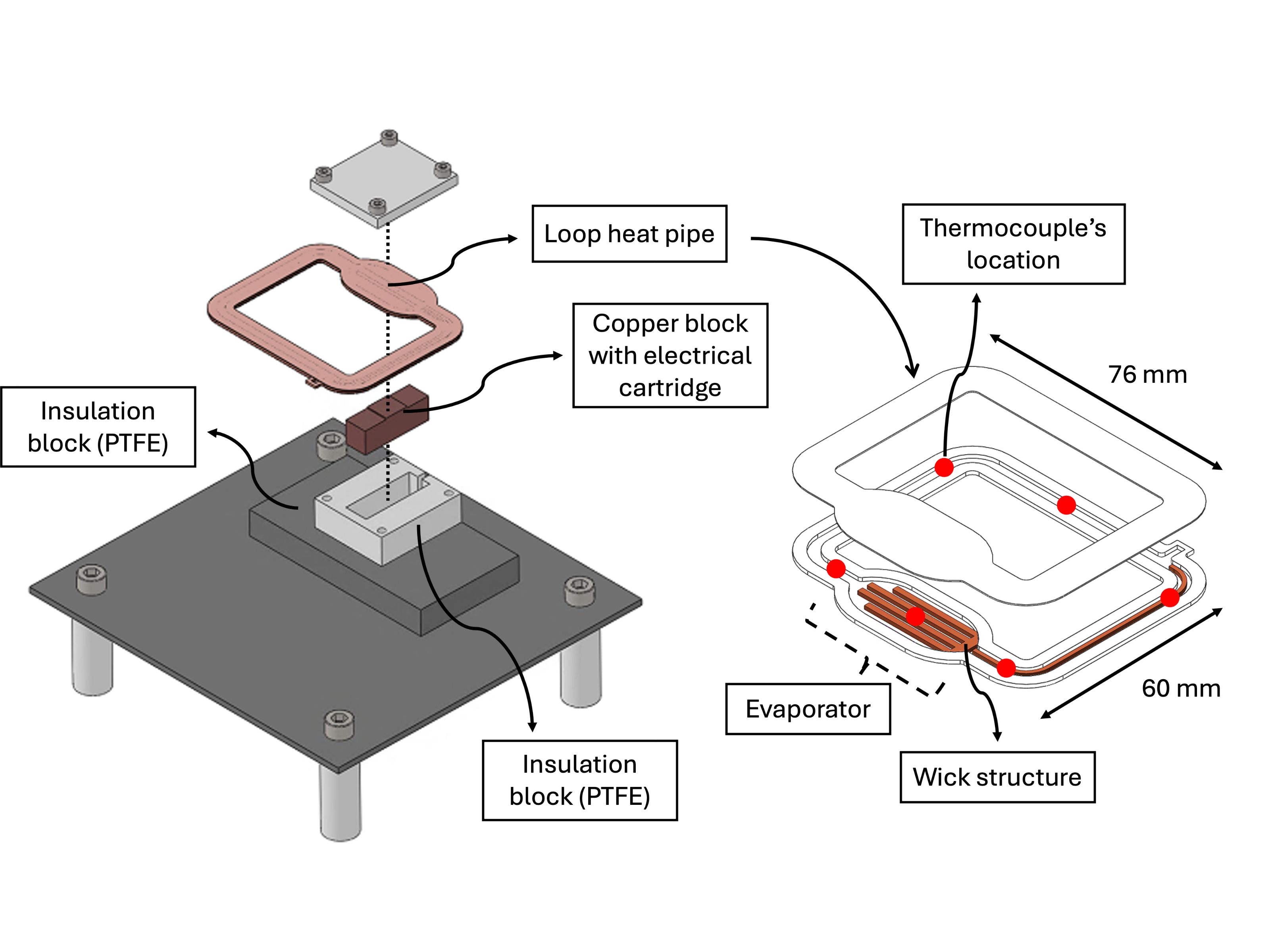
The proposed flat LHP was specially designed for removing the excess heat from chip processors of smartphones. The device consisted of two external copper plates, each 0.3 mm thick, and a machined copper frame, made from a 0.3 mm thick plate, provided the channels in which the liquid flows. The device dimensions were 76 x 60 x 0.9 mm3, as shown in Figure 6.
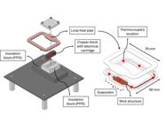
A copper powder wick structure was sintered in the evaporator, providing the necessary capillary pressure for the proper circulation of the working fluid. A wick was also provided in the liquid line to reduce vapor pressure variations and to guarantee liquid in the evaporator. The wick structure physical properties, particle average diameter, porosity, permeability and effective thermal conductivity were, respectively: 49.72 µm, 53.46%, (1.99 x 1.02) x 10-12 m2, 17.87 W/mK. The proposed device had an internal void volume of 0.27 ml. 0.17 ml of deionized and distilled water was used as the working fluid.
The developed flat LHP was tested in an experimental setup to evaluate the thermal performance. The experimental setup included a power source unit that applied thermal loads to the evaporator by a copper block of 1 cm2 of contact area with an electrical cartridge resistor inside. The heat load started with 0.5 W, followed by 1 W and then in increasing steps of 1 W, until the evaporator temperature reached 100 °C, considered a limit for the electronics applications. The evaporator section was insulated with PTFE polymer (Polytetrafluoroethylene), as shown in Figure 6. In the condenser, air natural convection was used to dissipate the heat to the environment, simulating typical conditions for chip processors of smartphones. Temperatures along the heat pipe were monitored using six thermocouples, as shown in the right side of Figure 6, where T1 is located in the evaporator temperature, T2 in the outlet evaporator, T3, T4 and T5 in the condenser inlet, mean and outlet regions, and T6 in the inlet of the evaporator. A data acquisition system DAQ-NI® SCXI-1000, connected to a computer, recorded all measurements in one second frequency. The thermal test was conducted in the horizontal position (the evaporator and the condenser were in the same level). Each heat load test last twenty minutes, to ensure steady-state conditions, considered reached when the temperature variations were less than 0.1 K/min.
The thermal performance of the LHP was evaluated by its thermal resistance, R [K/W], which measures the device's resistance to heat transfer between the heat source and the heat sink. The higher the resistance, the more difficult it is for the system to transfer heat, resulting in a higher temperature difference between the condenser and the evaporator. This thermal resistance can be calculated using the following equation:
where, q [W] is the thermal load applied to the evaporator, T1 and T4 are the temperatures of the thermocouples at the evaporator and condenser, respectively.
3. Results and Discussion
This section discusses several key topics related to the characterization and thermal performance of the developed flat loop heat pipe. First, the optical interferometry of sheets is presented, focusing on axonometric projections and roughness parameters. The optical microscopy technique is used to the bond interface and assess defects in the surface. In the sequence, the shear test evaluates the mechanical properties of the material, followed by the Vickers microhardness test to measure hardness at the microstructural level. Finally, the thermal performance of the loop heat pipe developed with the studied diffusion bonding parameters is detailed, verifying the effectiveness of the technique in the development of the two-phase device.
3.1. Optical interferometry of sheets: axonometric projections and roughness parameters
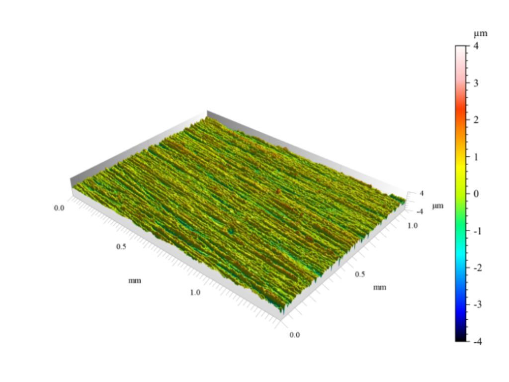
The results of the optical interferometry analysis are demonstrated by the typical axonometric projection of the copper sheet surface before the diffusion bonding process, as shown in Figure 7, and by the roughness values quantified in Sa, Sq, Sz, Sp, and Sv.
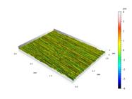
In Figure 7, the projection presents visible characteristics of the sanding performed during preparation for the bonding process. The sanding leaves the part with a linear and uniform orientation in the direction of the process, with several peaks and valleys dispersed throughout the surface.
This behavior with more valleys and peaks can negatively impact the joining by diffusion, since the heterogeneity of the sample causes larger voids in the initial contact between the surfaces to be joined, so that the amount of material to be transported through diffusive phenomena and thus the time required to completely fill the voids between the joined surfaces increased.
The roughness results obtained included the parameters Sa, defined as the average surface roughness, and Sq, defined as the root mean square roughness of the surface. The average Sa value was 0.462 μm, with a standard deviation of 0.063 μm. The Sq value had an average of 0.647 μm and a standard deviation of 0.100 μm. These results were consistent, as Sq, being a root mean square parameter, is more sensitive to variations in surface height compared to Sa. For diffusion bonding, it is desirable that the values of Sa and Sq are close to zero, a value that can be achieved by a smooth surface. However, since this parameter is an average, it is important to consider other parameters to separately analyze the peaks and valleys present on the surface.
Thus, the parameters Sz, Sp, and Sv were evaluated. The average Sz value was 7.106 μm, with a standard deviation of 0.993, while the average Sp value was 2.652 μm with standard deviation of 0.362, and Sv value was 4.454 μm and standard deviation of 1.165.
Sz represents the sum of the Sv e Sp values for each point, indicating the maximum total height of a given point measured by the interferometer. Values close to zero suggest a more leveled surface, resulting in a greater number of contact points in diffusion bonding. However, for the joining process, it is more appropriate to consider the Sp and Sv values separately, as peaks tend to be flattened and deformed under applied pressure, while valleys may be filled during the process.
The rolling process contributes to peak flattening when Sp is lower than Sv, reducing this surface roughness value. Additionally, sanding during the preparation for diffusion bonding further enhances this effect by leveling the surface. Conversely, if Sv is higher than Sp, the valleys may not be completely filled when pressure is applied during the joining process. This incomplete filling can result in defects at the joining interface, influencing the mechanical integrity of the bonded material.
3.2. Optical microscopy
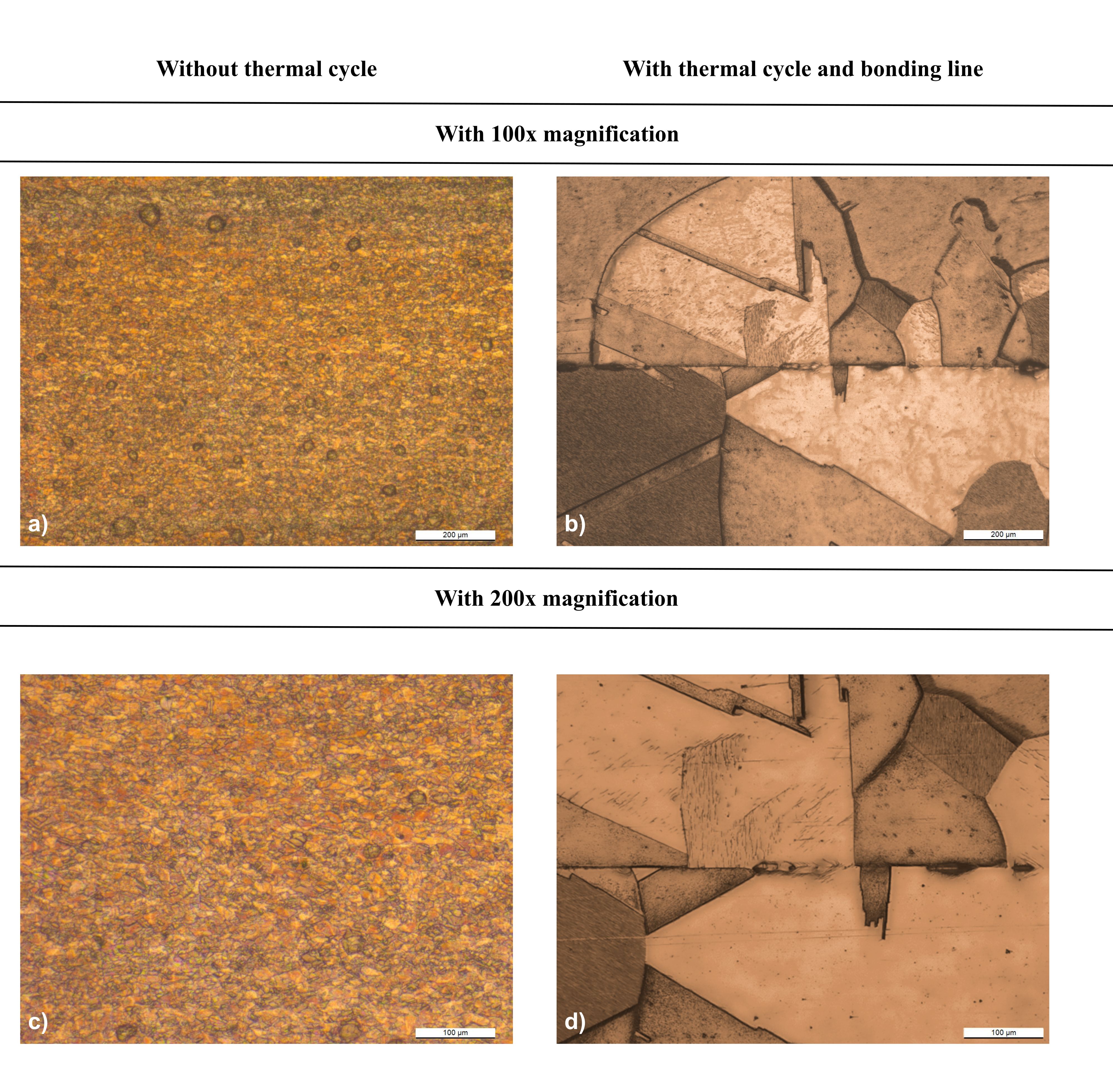
The typical microstructures of the base material before thermal cycling (a and c) and for the bonded samples (b and d) are shown in Figure 8 at magnifications of 100x and 200x. For the base material, a fine grain size can be observed, which is characteristic of materials subjected to cold working processes, such as the cold rolling process employed in the manufacturing of the copper sheets analyzed in this study. In the diffusion bonded sample, larger grains are observed, indicating the occurrence of phenomena such as recrystallization and grain growth during the thermal cycle. Furthermore, this grain growth will lead to a reduction in the mechanical strength of the bonded samples, which can be confirmed in the shear test.
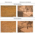
Typical micrographs of the base material of the sheets before thermal cycling (a and c) and of the bonded samples after thermal cycle (b and d) at 100x. and 200x.
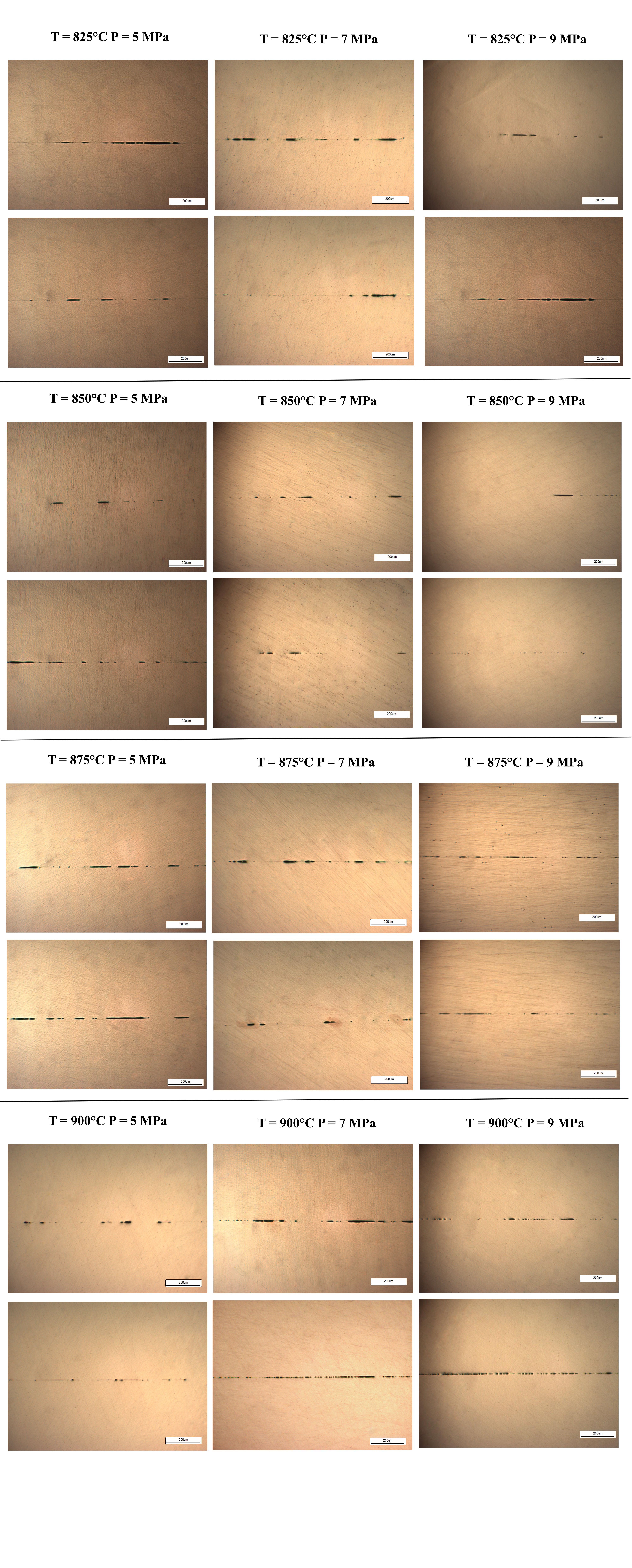
Figure 9 presents two micrographs for each condition at the bond interface in a magnification of 100x, organized into three columns corresponding to the pressures of 5, 7, and 9 MPa, respectively and for each temperature of 825 ºC, 850 ºC, 875 ºC, and 900 ºC.

Micrographs typical of the bond interfaces at a magnification of 100x after thermal cycling.
In general, defects were observed in all analyzed bonding interfaces. These defects predominantly exhibit an elongated morphology, although, in certain conditions, more rounded, smaller defects are also identified, distributed throughout the bonding region.
The elongated and continuous defects observed in specific areas can negatively affect the mechanical performance of the equipment, as they act as critical points for crack nucleation. A significant presence of defects indicates that complete void filling did not occur during the volumetric diffusion stage under all evaluated conditions.
These results can be explained by the inadequate surface roughness of the sheets, as surfaces characterized by deep valleys can lead to larger voids in the bonding line during the diffusion bonding process. Another possible explanation is the presence of an oxide layer between the surfaces, which can inhibit atomic diffusion and compromise bond quality.
Considering the analyzed pressures and temperatures, it was found that increasing the applied pressure directly influences the morphology of the defects. Samples subjected to a pressure of 9 MPa exhibited more rounded and smaller defects, particularly at temperatures of 850 °C, 875 °C, and 900 °C. In contrast, samples bonded under pressures of 5 MPa and 7 MPa predominantly showed elongated defects, indicating a smaller effective bonding area. This behavior can be explained by the lack of plastic deformation to break the asperities and ensure intimate contact between the surfaces.
Samples bonded at a temperature of 825 °C exhibited highly elongated defects for all evaluated pressures, which can directly impact the mechanical resistance of the samples. Meanwhile, the best qualitative results were observed in samples bonded at 9 MPa across all evaluated temperatures, indicating a better quality bond.
3.3. Shear test
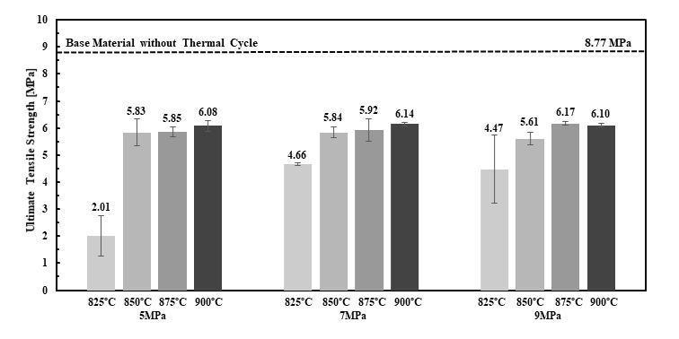
Figure 10 shows the average of the tensile strength results achieved by the samples joined under the twelve conditions studied. The conditions that supported the highest tensile strength were those with the highest temperature (900 °C) for all pressures, along with the 9 MPa and 875 °C samples.
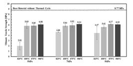
In the present study, it was not possible to establish a direct relationship between tensile strength and applied pressure. However, for each analyzed pressure condition, it is observed that increasing the temperature results in a higher maximum stress supported by the material. However, the temperature of 825 °C presented the worst results across all pressure conditions, exhibiting the lowest tensile strength values. These results indicate a significant influence of temperature on tensile strength, possibly due to the increased atomic diffusion between the bonded surfaces, which may enhance the bond quality.
Nevertheless, all tested conditions exhibited lower tensile strength than the base material in its as-received condition (without thermal cycling). This behavior can be attributed to the fact that the base material is cold-rolled, a process that naturally provides higher mechanical strength due to work hardening. In contrast, the samples subjected to the thermal cycle underwent an annealing process, leading to a reduction in material strength. Furthermore, the presence of defects at the bonding interface acts as a stress concentrator, promoting failure at lower applied stresses.
3.4. Vickers microhardness test
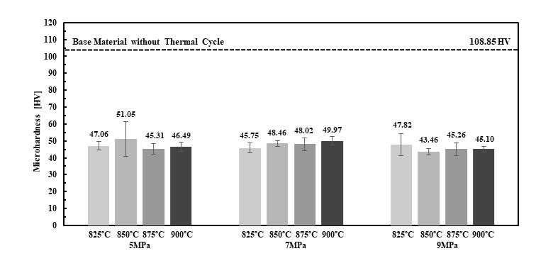
Figure 11 shows the average Vickers microhardness for the twelve conditions, with eight points measured in each condition. The results indicate a decrease in hardness when compared to the base material (108.85 HV) for all bonded samples. These results are expected, as the copper sheets underwent a cold rolling process, which inherently induces a certain degree of strain hardening. As the thermal cycle progresses, annealing takes place, leading to the relief of residual stress and the consequent reduction in hardness.
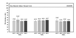
When compared across all bonding conditions the microhardness exhibits no significant difference, with values ranging from 43.46 to 51.05 HV. These results are explained due to the high temperature necessary for the diffusion bonding, which promotes the complete recrystallization and annealing of the base material within minutes, followed by grain growth promoting even further decrease in hardness.
These results are in agreement with the ones observed by Solouki et al.36, in which the authors evaluate the high-temperature annealing behavior of cold-rolled electrolytic tough-pitch copper. In their work, the authors observed that when annealing electrolytic copper at 400 ºC, the hardness rapidly falls from 130 HV when cold worked to 57 HV in 10 minutes and then keeps close to 54 HV for treatments up to 120 minutes.
The observed deviation in the results is likely attributed to the formation of oxidation points in the samples. Given that copper oxides exhibit significantly higher hardness, their presence and quantity may lead to an increase in the measured values of hardness.
From the obtained results, it can be concluded that an effective bonding can be achieved at temperatures above 850 °C and pressures above 5 MPa, both mechanical properties and tightness achieved the minimum requirements for the application. Considering that the device has internal channels, an intermediate set of parameters was defined in order to minimize the plastic deformation of the heat pipe during diffusion bonding while ensuring proper bonding. Based on the analysis of the maximum shear stress achieved (5.92 MPa), hardness (48.02 HV), and defect distribution—where defects appeared more dispersed, indicating a larger bonding area, as well as having smaller diameters and less elongation—the final parameters for LHP fabrication were established: a temperature of 875 °C, a pressure of 7 MPa, and a duration of 1 hour.
3.5. Thermal performance of the flat loop heat pipe
Before thermally testing the manufactured LHP, a tightness test was carefully performed using a vacuum leakage detector (Pfeiffer vacuum ASM340) with helium to validate the optimized diffusion bonding parameters (875 °C, 7 MPa, and 3600 s) to fabricate an LHP in copper. This procedure showed consistent results as no leakage was detected. After that, the LHP was validated and the thermal tests can be performed.
The first step of the thermal test was to provide vacuum, followed by the working fluid charging (0.17 ml of water). These procedures must be carefully realized to ensure the proper operation of the heat pipe. More details can be found in Domiciano et al.6,7,37.
For the proper startup of an LHP, when the device works in a two-phase flow regime, a temperature difference between the condenser and the working fluid vapor-liquid interface in the evaporator is required. Considering the evaporator wick structure fully saturated with liquid, when heat is applied on the evaporator outer surface, the liquid starts to change of phase to vapor. With the temperature increase, the vapor pressure also increases, up to the level when they are higher than the working fluid pressure along the device, allowing the fluid to circulate. At the condenser, the vapor shows two effects: increase the condenser temperature, while condensates to liquid phase, due the air natural convection. The capillary pressure, mainly developed in the evaporator, pushes the liquid back to the evaporator, completing the thermodynamic cycle.
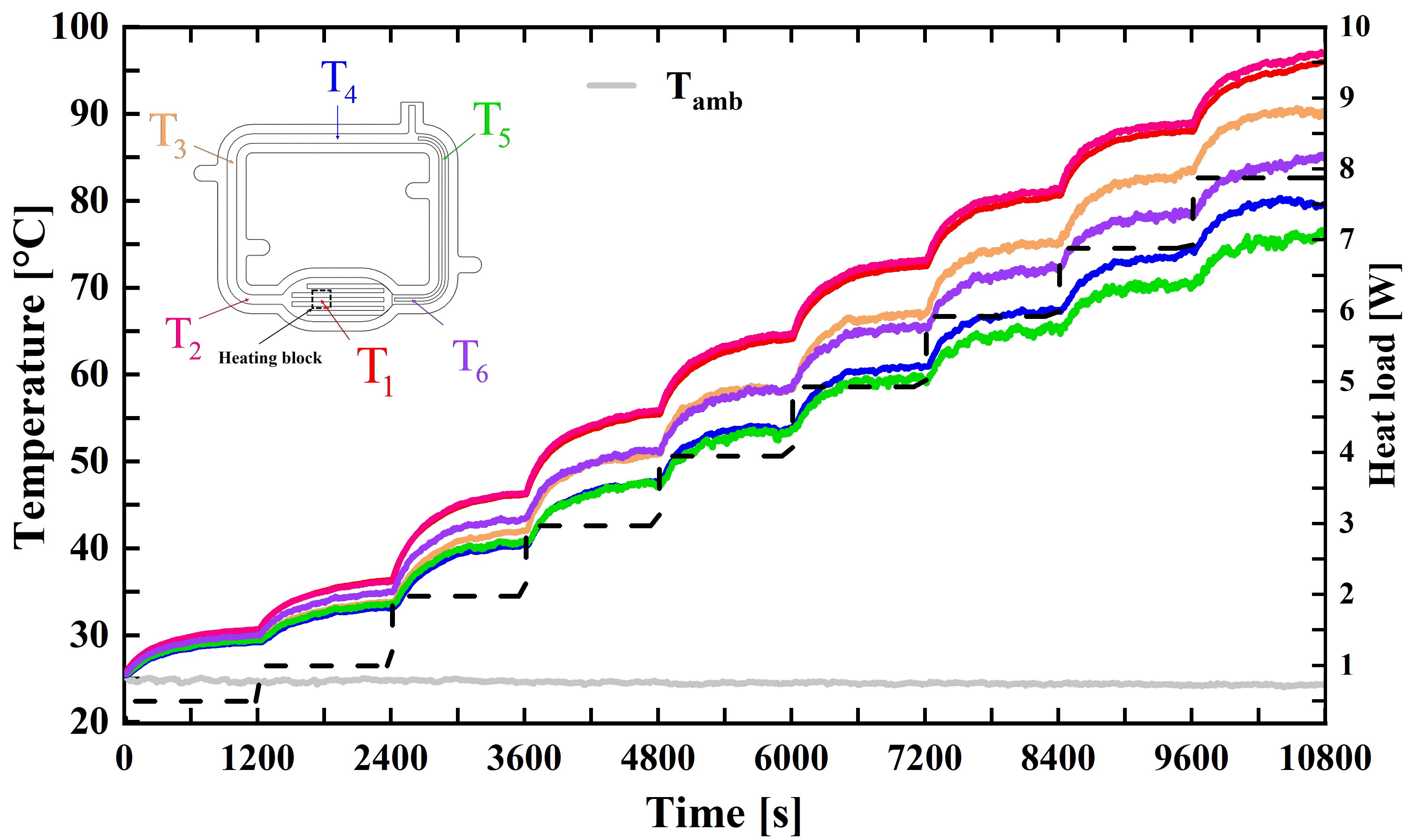
Figure 12 shows the temperature distribution of the LHP during the thermal test, where one can see that the temperatures increase as the thermal loads are applied, eventually reaching steady-state conditions. This LHP reached the startup at 2 W, observed by the rise of the inlet condenser temperature (T3), almost reaching the same level of the inlet evaporator temperature (T6), showing that the vapor reached the condenser, as previously commented. At the startup power (2 W), the necessary temperature difference between T1 (evaporator temperature, red solid line) and T4 (inlet evaporator temperature, purple solid line) for the proper operation of the LHP was of 5.81 °C. With the increasing thermal load, the LHP was able to transfer heat more efficiently as T3 and T4 levels where closer of the evaporator temperature. It can be noted that T5 is the lowest temperature, meaning that the condensation probably ended at this point, in the beginning of the wick structure. Another important observation is that T6 is higher than T5, due to the conduction heat leakage from the evaporator to the condenser through the metal casing material. The maximum heat transfer capacity of the LHP was 8 W/cm2, before reaching the maximum temperature limitation of 100 °C. No overshoot of the evaporator temperature was observed in the tested conditions, which means that no dry out occurred and that the LHP could transfer higher heat loads if higher temperatures were allowed.
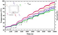
Temperature distribution of the loop heat pipe during the thermal test in the horizontal orientation.
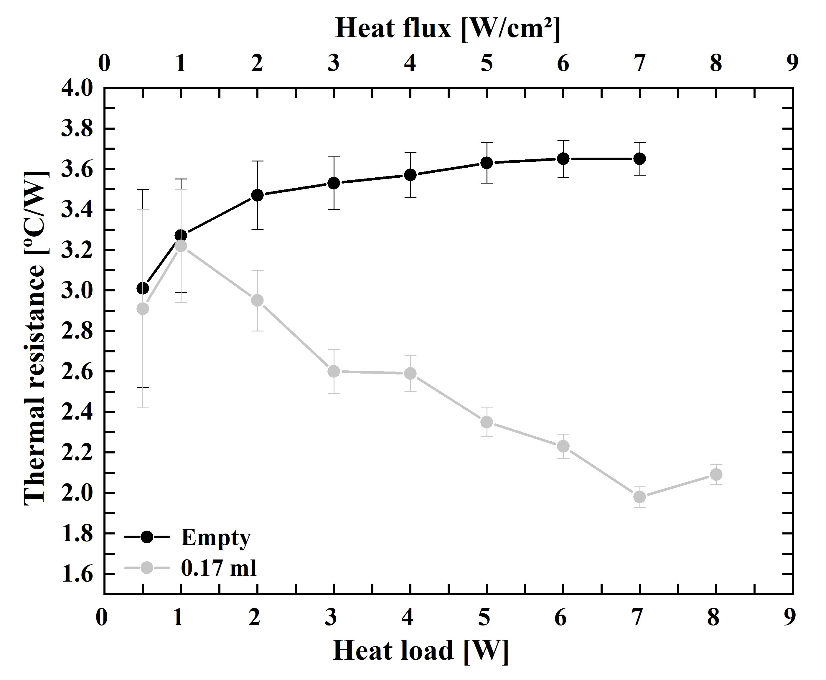
Figure 13 shows the thermal resistances of the flat LHP for thermal loads from 0.5 to 8 W, with the experimental uncertainties, obtained following the procedures proposed in6,7,37,38, shown by the vertical bars. For comparison, the average value of the thermal resistance of the empty device, i.e., operating only by conduction, is shown in (black line) the same graph. The average thermal resistance of the LHP transferring heat by only conduction was 3.62 ± 0.09 K/W. According to Figure 12, the thermal resistance of the heat pipe with 0.17 ml of working fluid (grey line) has been drastically reduced compared to the empty device, demonstrating the high efficiency of the heat pipe developed, with a minimum thermal resistance of 1.98 ± 0.05 K/W at 7 W.
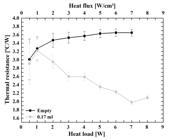
The thermal results of the diffusion-bonded LHP demonstrated that this small device, with only 0.9 mm of thickness, was capable of transporting up to 8 W successfully. In this context, the proposed parameters for diffusion bonding of copper demonstrated to be an excellent alternative for the fabrication of mini loop heat pipes intended for the thermal management of electronic equipment.
4. Conclusion
In this research, the parameters for the diffusion bonding of copper for the manufacturing of mini heat pipes were studied and optimized. Several combinations of pressure and temperature bonding were tested, and the resulting bonding pieces were characterized by microhardness, roughness, shear stress and microstructure. From the optical microscopy results it can be concluded that the most suitable manufacturing conditions were obtained for pressures of 9 MPa and temperatures of 850 °C, 875 °C and 900 °C. The observed defects in the joining surfaces were round and well distributed across the bond interface. The shear results support these findings as these conditions presented higher maximum ultimate tensile. Furthermore, from temperatures of 850°C, for all pressures suitable ultimate tensile strength values were achieved, next to the highest values, indicating that the pressure and temperature were sufficient to diffusion bonding the material.
Microhardness measurements revealed no significant difference between samples manufactured in different bonding conditions, with results ranging from 43 to 51 HV. This slight deviation in microhardness can be explained due the copper oxides formation in some of the evaluated regions. When compared with the as-received base material (108.85 HV), a reduction above 50% in microhardness was observed. This result is expected since the high temperature used during the diffusion bonding promotes the copper complete annealing and recrystallization in minutes, eliminating the residual hardening due to the cold rolling process. Grain growth is also observed and is directly associated with the decrease in microhardness after the bonding cycles.
The temperature of 875 °C and a pressure of 7 MPa applied during an hour was selected as the best set of parameters for the diffusion bonding of copper flat heat pipes. According to the results, the temperature presented a higher impact in the bonding quality in the diffusion bonding of copper, when compared with the pressure. Future work should be conducted on verifying the influence of bonding time, since increasing bonding time permits more specimens to be dislocated through diffusion mechanisms, promoting the closure of bigger voids.
Applying these optimized parameters to manufacture a flat miniature two-phase device proved suitable to produce reliable heat pipes with no deformation, high quality, and tightness proof. The loop heat pipe fabricated showed excellent thermal performance, capable of transferring up to 8 W of heat load before reaching the temperature limit of 100 °C, being, therefore, suitable for electronic applications.
The study brought to the literature insights on the copper diffusion bonding parameters that can be applied directly in the research and the manufacturing industry, enabling the application of this process in miniature heat pipes and other devices.
5. Acknowledgments
The authors would like to acknowledge the Brazilian Federal Agency for Support and Evaluation of Graduate Education (CAPES) for the scholarship under grant numbers 88887.954946, 88887.748453 and 88887.718636, National Council for Scientific and Technological Development (CNPq), National Fund for Scientific and Technological Development (FNDCT), and Ministry of Science, Technology, and Innovations (MCTI) for the project fundings 441678/2023-8 and 405784/2022-8, and scholarship under grant number 381267/2023-7, the Foundation for Research Support of Santa Catarina (FAPESC) for providing a scholarship under grant number 3003/2021. Also, acknowledgements are provided to Precision Mechanics Laboratory (LMP/UFSC) and Materials Laboratory (Labmat/UFSC) that provided several of the used measuring equipments.
6. References
- 1 Peterson GP. An introduction to heat pipes: modeling, testing, and applications. Hoboken: Wiley; 1994.
- 2 Mantelli MBH. Thermosyphons and heat pipes: theory and applications. Cham: Springer; 2020.
- 3 Tang H, Tang Y, Wan Z, Li J, Yan W, Lu L, Li Y, Tang K. Review of applications and developments of ultra-thin micro heat pipes for electronic cooling. Appl Energy. 2018;223:383-400.
-
4 Betancur L, Facin A, Gonçalves P, Paiva K, Mantelli M, Nuernberg G. Study of diffusion bonded flat plate closed loop pulsating heat pipes with alternating porous media. IOP Conf Ser Mater Sci Eng. 2021;1139(1):012001. http://doi.org/10.1088/1757-899X/1139/1/012001
» http://doi.org/10.1088/1757-899X/1139/1/012001 -
5 Krambeck L, Domiciano KG, Mantelli MBH. A new flat electronics cooling device composed of internal parallel loop heat pipes. Exp Comput Multiph Flow. 2024;6(3):277-86. http://doi.org/10.1007/s42757-024-0187-0
» http://doi.org/10.1007/s42757-024-0187-0 -
6 Domiciano KG, Krambeck L, Flórez JPM, Mantelli MBH. Thin diffusion bonded flat loop heat pipes for electronics: Fabrication, modelling and testing. Energy Convers Manage. 2022;255:115329. http://doi.org/10.1016/j.enconman.2022.115329
» http://doi.org/10.1016/j.enconman.2022.115329 - 7 Domiciano KG, Krambeck L, Mera JPF, Mantelli MBH. Study of a new thin flat loop heat pipe for electronics. Heat and Mass Transfer. 2023;59:2035-56.
-
8 Shioga T, Mizuno Y, Nagano H. Operating characteristics of a new ultra-thin loop heat pipe. Int J Heat Mass Transf. 2020;151:119436. http://doi.org/10.1016/j.ijheatmasstransfer.2020.119436
» http://doi.org/10.1016/j.ijheatmasstransfer.2020.119436 -
9 Shioga T, Abe T, Nagano H. Submillimeter-thick loop heat pipes fabricated using two-layer copper sheets for cooling electronic applications. Appl Therm Eng. 2020;181:116018. http://doi.org/10.1016/j.applthermaleng.2020.116018
» http://doi.org/10.1016/j.applthermaleng.2020.116018 -
10 Krambeck L, Domiciano KG, Betancur-Arboleda LA, Mantelli MBH. Novel flat plate pulsating heat pipe with ultra sharp grooves. Appl Therm Eng. 2022;211:118509. http://doi.org/10.1016/j.applthermaleng.2022.118509
» http://doi.org/10.1016/j.applthermaleng.2022.118509 -
11 Mortean MVV, Buschinelli AJA, de Paiva KV, Mantelli MBH, Remmel J. Soldagem por difusão de aços inoxidáveis para fabricação de trocadores de calor compactos. Soldag Insp. 2016;21(1):103-14. http://doi.org/10.1590/0104-9224/SI2101.10
» http://doi.org/10.1590/0104-9224/SI2101.10 - 12 Mortean MVV, Cisterna LHR, Paiva KV, Mantelli MBH. Development of diffusion welded compact heat exchanger technology. Appl Therm Eng. 2016;93:995-1005.
- 13 Jerry EG. Mechanisms of bonding for solid-state welding processes. In: Lienert T, Siewert T, Babu S, Acoff V, editors. Welding fundamentals and processes. Materials Park, OH: ASM International; 2011. p. 171-8.
- 14 Mahoney MW, Bampton CC. Fundamentals of diffusion bonding. In: Olson DL, Siewert TA, Liu S, Edwards GR, editors. Welding, brazing, and soldering. Materials Park, OH: ASM International; 2018. p. 156-9.
-
15 Derby B, Wallach ER. Joining methods in space: a theoretical model for diffusion bonding. Acta Astronaut. 1980;7(4-5):685-98. http://doi.org/10.1016/0094-5765(80)90052-1
» http://doi.org/10.1016/0094-5765(80)90052-1 -
16 Gietzelt T, Toth V, Huell A. Diffusion bonding: influence of process parameters and material microstructure. In: Ishak M, editor. Joining technologies [Internet]. Rijeka: IntechOpen; 2016 [cited 2025 Apr 9]. Available from: https://www.intechopen.com/books/5257
» https://www.intechopen.com/books/5257 - 17 Lee HS. Diffusion bonding of metal alloys in aerospace and other applications. In: Chaturvedi MC, editor. Welding and joining of aerospace materials. Elsevier; 2012. p. 320-44.
- 18 Kazakov NF. Diffusion bonding of materials. Vol. 1. Oxford: Pergamon; 1985. 304 p.
-
19 Dunkerton SB. Procedure development and practice considerations for diffusion welding. In: Lienert T, Siewert T, Babu S, Acoff V, editors. Welding, brazing and soldering. Materials Park, OH: ASM International; 1993. p. 883-7. http://doi.org/10.31399/asm.hb.v06.a0001446
» http://doi.org/10.31399/asm.hb.v06.a0001446 - 20 Mortean M. Desenvolvimento de tecnologia de recheios para trocadores de calor compactos soldados por difusão [dissertation]. Florianópolis: Universidade Federal de Santa Catarina; 2014.
-
21 Betancur-Arboleda L, Hulse P, Melian I, Mantelli M. Diffusion-bonded pulsating heat pipes: fabrication study and new channel proposal. J Braz Soc Mech Sci Eng. 2020;42(9):466. http://doi.org/10.1007/s40430-020-02555-4
» http://doi.org/10.1007/s40430-020-02555-4 -
22 Somers-Neal S, Phan N, Watanabe N, Ueno A, Nagano H, Saito Y. Experimental and numerical investigations of a diffusion bonded flat-type loop heat pipe for passive thermal management. Appl Therm Eng. 2024;257(Pt C):124485. http://doi.org/10.1016/j.applthermaleng.2024.124485
» http://doi.org/10.1016/j.applthermaleng.2024.124485 -
23 Vieira K, Paiva D, Mantelli M, Slongo LK, Gohr R, Vieira De Paiva K, et al. Experimental tests of wire mini heat pipe under microgravity conditions aboard suborbital rockets [Internet]. 2008 [cited 2025 Apr 9]. p. 1-7. Available from: https://www.researchgate.net/publication/228822870
» https://www.researchgate.net/publication/228822870 -
24 Wang M, Yang Y, Sun Y, Li J, Hao M. Experimental study on the thermal performance of ultra-thin flat heat pipes with novel multiscale striped composite wick structures. Heliyon. 2023;9(10):e20840. http://doi.org/10.1016/j.heliyon.2023.e20840 PMid:37867792.
» http://doi.org/10.1016/j.heliyon.2023.e20840 -
25 Betancur-Arboleda LA, Flórez Mera JP, Mantelli M. Experimental study of channel roughness effect in diffusion bonded pulsating heat pipes. Appl Therm Eng. 2020;166:114734. http://doi.org/10.1016/j.applthermaleng.2019.114734
» http://doi.org/10.1016/j.applthermaleng.2019.114734 -
26 Silk EA, Myre D. Fractal Loop Heat Pipe performance testing with a compressed carbon foam wick structure. Appl Therm Eng. 2013;59(1-2):290-7. http://doi.org/10.1016/j.applthermaleng.2013.05.030
» http://doi.org/10.1016/j.applthermaleng.2013.05.030 -
27 Kang SW, Tsai SH, Ko MH. Metallic micro heat pipe heat spreader fabrication. Appl Therm Eng. 2004;24(2-3):299-309. http://doi.org/10.1016/j.applthermaleng.2003.08.008
» http://doi.org/10.1016/j.applthermaleng.2003.08.008 -
28 Vieira De Paiva K, Barbosa Henriques Mantelli M, Kessler Slongo L. Thermal behavior analysis of wire mini heat pipe. J Heat Transfer. 2011;133(12):121502. http://doi.org/10.1115/1.4004526
» http://doi.org/10.1115/1.4004526 - 29 Jose J, Kumar Hotta T. A comprehensive review of heat pipe: its types, incorporation techniques, methods of analysis and applications. Vol. 42, Thermal Science and Engineering Progress. USA: Elsevier Ltd; 2023.
- 30 Krambeck L. Flat mini heat pipe technologies for the thermal management of electronics [thesis]. Florianópolis: Universidade Federal de Santa Catarina; 2024.
-
31 Coppermetal. Tudo sobre o tubo de cobre eletrolítico [Internet]. Socorro: Coppermetal; 2025 [cited 2025 Apr 9]. Available from: https://www.coppermetal.com.br/blog/tubo-de-cobre-eletrolitico/
» https://www.coppermetal.com.br/blog/tubo-de-cobre-eletrolitico/ -
32 ASTM International. B152/B152M – 19: Specification for Copper Sheet, Strip, Plate, and Rolled Bar [Internet]. West Conshohocken, PA: ASTM International; 2019 [cited 2025 Apr 9]. Available from: http://www.astm.org/cgi-bin/resolver.cgi?B152B152M-19
» http://www.astm.org/cgi-bin/resolver.cgi?B152B152M-19 -
33 Tsai MC, Kang SW, Vieira De Paiva K. Experimental studies of thermal resistance in a vapor chamber heat spreader. Appl Therm Eng. 2013;56(1-2):38-44. http://doi.org/10.1016/j.applthermaleng.2013.02.034
» http://doi.org/10.1016/j.applthermaleng.2013.02.034 - 34 Norton R. Machine design: an integrated approach. 6th ed. Londres; Pearson PLC; 2019.
-
35 Amaral MC, de Andrade Caldas L, Martins BM, Holtz IT, da Costa Gonçalves P, Cardoso RP, et al. The surface quality of 316L sheets after abrasive waterjet, photochemical machining, and electropolishing for compact heat exchangers. Int J Adv Manuf Technol. 2024;131(9-10):5061-74. http://doi.org/10.1007/s00170-024-13321-4
» http://doi.org/10.1007/s00170-024-13321-4 -
36 Solouki H, Jamaati R, Jamshidi Aval H. High-temperature annealing behavior of cold-rolled electrolytic tough-pitch copper. Heliyon. 2024;10(12):e33276. http://doi.org/10.1016/j.heliyon.2024.e33276 PMid:39027440.
» http://doi.org/10.1016/j.heliyon.2024.e33276 -
37 Guessi Domiciano K, Krambeck L, Barbosa Henriques Mantelli M. Novel mini loop heat pipe with twisted wires as wick structure. Appl Therm Eng. 2025;260:124992. http://doi.org/10.1016/j.applthermaleng.2024.124992
» http://doi.org/10.1016/j.applthermaleng.2024.124992 - 38 Holman JP. Experimental methods for engineers. 8th ed. New York: McGraw-Hill; 2011. (Mcgraw-hill Series in Mechanical Engineering).