
 Low computational cost formulation for the analysis of the Soil-Structure Interaction in frames considering the equilibrium in the deformed soil condition
Abstract
Lattice structures have a wide range of applications in real structures. For example, concrete buildings can be modeled as flat or spatial frames, while lattice or ribbed slabs can be modeled as grids. Computer programs frequently used for the design of buildings in Brazil allow the design to be carried out in spatial gantry and grid. Also, some include the possibility of applying calculated support settlements or manually introducing an elastic spring to simulate the behavior of the foundation. However, it is not possible to insert geotechnical data together with the structure for the geotechnical evaluation of soil deformation in an integrated way to obtain an analysis of the interaction between the stresses in the structure and the soil deformations, as well as to take into account the overlapping of stresses applied in the soil mass to evaluate settlements. In this context, classical solutions to analyze these domains together have been proposed with the use of the Finite Element Method (FEM) and by the coupling between the Boundary Element Method (SEM) and FEM. Despite being robust, these techniques are not yet commonly used in calculation offices, due to the high computational cost. In this sense, alternative formulations with lower computational cost, such as the one proposed herein, can be a viable alternative for the analysis of the effects of soil-structure interaction in conventional structures without significantly impairing computational performance. Thus, to approximate the computational analysis to the real behavior of structures, this article proposes an efficient and low-cost computational matrix analysis solution for the integration between structural and geotechnical models, considering the soil-structure interaction. Thus, the integrated model considers the compatibility between the forces calculated in the structure and the settlement prediction, carried out, considering the soil deformation caused by the global contribution of stresses, in such a way as to consider in the analysis of the soil, both the tensions arising from the support itself and those transmitted by the other foundation elements. The proposed alternative formulation was verified for isolated structural analyses, geotechnical isolates and finally considering the coupled form with equilibrium in the deformed condition of the soil, paying attention to the robustness of the implementation.
Keywords:
soil-structure interaction; matrix analysis; settlement forecast; alternative formulation; low computational cost.
1. Introduction
In some cases of Building projects, the structure is designed to be supported on non-movable supports. However, the differential movement of the supports by the foundation settlements introduces additional stresses on hyperstatic structures. In this context, Souza and Reis (2008) found that the hypothesis of totally rigid support can lead to important distortions in the forces suffered by the columns in reinforced concrete buildings. Bahia, Cunha and Mota (2021) noted a reduction in settlements, calculated from the Soil-Structure Interaction (SSI), and an increase in the requesting efforts in the structure. Thus, the non-consideration of the SSI may mean undersizing of the characteristic efforts, which contributes to the importance of considering SSI even in regular building projects. In the same way, the NBR 6118 (2014) design standard reinforces the importance of soil-structure interaction, since it establishes that, at least in more complex cases, the interaction between these domains must be considered in the design of the structural model.
It is noted that in recent decades, there has been a great increase in the numerical processing capacity of computers, thus allowing the conception of virtual models to be more widespread and used (Bittencourt, 2010). Thus, it becomes increasingly pertinent to develop new computational tools that provide the improvement of engineering conceptions and projects. In this sense, classical solutions to analyze these domains together have been proposed using the Finite Element Method (FEM) as developed by Farias (2018), Dhadse, Ramtekkar and Bhatt (2021), Tamayo and Awruch (2016) or by coupling the Boundary Element Method (BEM) and FEM, as in Luamba (2022), Silva (2020), Silva (2014), Ramos (2013), Yazdchi, Khalili and Valliappan (1999).
Robust alternative methods for analyzing Soil-Structure Interaction have also been proposed, such as the Particle Finite Element Method (PFEM) (Carbonell et al., 2022; Monforte et al., 2016 and Monforte et al., 2018) and those based on machine learning (Ali.; Eldin; Haider, 2023, Shrestha; Gupta; Ghani, 2024 and Ouyang, 2024).
Despite being robust, it is observed that these techniques are not yet commonly used in calculation offices, due to the high computational cost. In this sense, quasi-analytical formulations with lower computational cost, such as the one proposed herein, can be a viable alternative for the analysis of the effects of Soil-Structure Interaction in conventional structures without significantly impairing computational performance.
Souza and Reis (2008) analyzed the interaction between the soil and the structure using a simplified methodology to calculate the settlements from the forces on the supports and later recalculate the structure considering the calculated deformation. However, the model proposed by Souza and Reis (2008) considers only the influence of isolated stresses from the whole, in such a way that there is no consideration of the mutual effects of stress propagation in the soil mass from one foundation to another and there is no integration in a single program. In this sense, Mundim, Cruvinel and Cavalcanti (2014) implemented a numerical tool for predicting settlements in footings, considering, in addition to the individual settlements, the deformations arising from the interference of the other footings of the structure in this element. The article presented strong indications that the consideration of the effects of stress propagation between foundations is significant for the evaluation of soil deformation. Although this study allows efficient analysis with low computational cost, there was no integration with the structure.
Bahia, Cunha and Mota (2021) analyzed the performance of tall buildings using Soil-Structure Interaction using a simplified coupling methodology with two external programs (TQS and GARP). This form of soil-structure interaction is not carried out internally in a single program, that is, there is a need to use two programs to obtain the final solution, which can impair usability in project offices. Thus, the studies of Souza and Reis (2008), Mundim, Cruvinel and Cavalcanti (2014) and Bahia, Cunha and Mota (2021) leave room for complementation in order to integrate the analysis of the joint deformations of the stratified soil mass with the deformations of the structure in an iterative way, providing a refinement to the traditional model of structure analysis.
The purpose of the present study is to perform this integration in an academic computer program, developed specifically for this purpose. The proposed formulation aims to be more practical and with lower processing cost than the coupling versions with FEM or MEC, in this sense solutions of the Theory of Elasticity will be used to evaluate the propagation of stresses in the soil. It is worth noting that the proposed model also allows the integration of the structure with geotechnical field tests, such as, for example, the Dilatometric Marchetti Test - DMT standardized by ASTM D6635:15 in the United States (ASTM D6635:15, 2015) and by ISO 22476-11:2017 in Europe (ISO 22476-11, 2017), Pressiometric Test - PMT regulated by ASTM D4719:2007 (ASTM D4719, 2007) and the Standard Penetration Test - SPT standardized by NBR 6484 (ABNT NBR 6484, 2020). In addition, the proposed study is justified because in addition to proposing a low-cost computational tool for the integrated and automatic analysis of the Soil-Structure Interaction, it will also allow the global evaluation of settlements, considering the effects of stress propagation in the solid soil medium. Thus, the effect that stress applied to the ground by a column exerts on the deformation of adjacent columns due to the mutual interaction between the supports will be taken into account. In addition, it will also allow the evaluation of stratified soils, with different stiffness characteristics in each layer and in each support base, which can be obtained by field tests such as DMT or PMT.
Therefore, the general objective of this study is to implement a quasi-analytical solution of low computational cost for the analysis of lattice structures in an integrated way with the geotechnical analysis of soil deformations, through an iterative design internal to the program. This formulation allows several practical applications in civil structures, such as the analysis of the Soil-Structure Interaction in buildings with differential settlement, such as warehouses or highway pavements.
2. Mathematical formulation
The matrix formulation of the method for displacements leads to a system of equations that can be written in matrix form as Equation (1) shows. The solution of this system of equations allows for obtaining the nodal displacements, and consequently, the support reactions and the requesting forces in the sections of the bars.
Where: the term KESTR represents the stiffness matrix of the structure, the term UESTR represents the displacement vector of the structure's nodes, and the term FESTR represents an external loading vector, all described in the global coordinate system.
In the matrix formulation of the displacement method, the stiffness matrix of the structure and the force vector are obtained through the proper assembly of the stiffness matrices and the equivalent force vectors of the elements that make up the structure. Both are formulated in the local coordinate system of each element, whose x-coordinate axis coincides with the axis of the member. The relationship between forces and displacements, in the global system, at the nodes of each element is presented in Equation (2). The same relationship can be written in the local coordinate system as shown in Equation (3).
Where: Kel, Uel, Fel are, respectively, the stiffness matrix, the nodal displacement vector, and the nodal force vector in the global coordinate system; Kel, uel, fel are, respectively, the stiffness matrix, the nodal displacement vector and the nodal force vector in the local coordinate system.
The relationships between forces and nodal displacements in the two coordinate systems are expressed in Equations (4) to (7). Equation (4) presents the transformation of forces from the local system to the global coordinate system; and Equation (5) presents the transformation of forces from the global system to the local coordinate system. Equation (6) shows the transformation of displacements from the local system to the global coordinate system; and Equation (7) presents the transformation of displacements from the global system to the local coordinate system.
Where: Rel represents the element's rotation matrix; and RelT represents the transposed rotation matrix.
From the element's stiffness matrix in the local system, kel, and its rotation matrix, Rel, it is possible to obtain the element's stiffness matrix in the global coordinate system, Kel. Substituting Equation (7) into Equation (3) and multiplying both sides of the Equation by RelT , and then applying Equation (4) to the resulting expression, one obtains Equation (8). Thus, comparing the expressions (2) and (8), it is noted that the element's stiffness matrix in the global coordinate system, Kel, is given by Equation (9).
The stiffness matrix, KESTR, is obtained by assembling the stiffness matrices of the elements, Kel, by associating the degrees of freedom of the element with the degrees of freedom of the structure, whose sum is expressed in (10).
Where: nel is the number of elements in the structure; gle indicates that the summation is made for the degrees of freedom of the structure.
Similarly, the stiffness matrix associated with the constraints, Kr, obtained by assembling the stiffness matrices of the elements, Kel, by associating the degrees of freedom of the element with the degrees of constraint of the structure, whose sum is expressed in (11).
Where: gre indicates that the summation is done for the degrees of constraint of the structure. Once the system of Equations expressed in (1) is solved, one can obtain the support reactions of the structure by Equation (12).
Where: R is the vector of the support reactions; and Kr is the matrix associated with the support constraints.
In the case of spring supports, the displacement in the direction of the spring must be considered as one of the degrees of freedom of the structure and the spring constant must be added to the term Kii of the KESTR matrix. Thus, the matrix R concerns only the support reactions related to the impeded displacements. The spring-related support reactions are obtained by Equation (13).
Where: Rm is the stance reaction associated with the spring m; km is the stiffness constant of spring m; and Um is the displacement associated with spring m, extracted from KESTR.
The soil will be considered as a continuous elastic medium for the evaluation of the propagation of stresses between adjacent supports. Pinto (2006) points out that the theory of elasticity can be applied in soil mechanics to estimate the stresses acting inside the soil mass as a function of surface or internal loads. The Newmark solution allows obtaining the value of the stress in the soil at a depth z resulting from a rectangular surface loading of boundary a x b. In addition, the solution refers only to the stress at the vertex of the region, a x b. Thus, to determine the solution at a point other than the vertex, it is necessary to use the sum of Newmark's solutions.
Although the soil does not present reversibility after being subjected to deformations, as occurs in elastic materials, up to a certain level of stresses, there is a proportionality between stresses and deformations (Pinto, 2006). Thus, a constant modulus of elasticity can be considered as representative of the soil up to a certain level of increased stress.
Equation (14) helps in the evaluation of stresses as a function of depth and distance from the region of application in an analytical way. Although extensive analytical functions require greater manual effort, in computational terms generalization is simple and more efficient Thus, the analytical expression of this equation is used to evaluate the increases in stresses at any point in the soil mass due to a constant surface loading in a rectangular region.
Where: the factors m and n are symmetric, such that their definitions can be reversed; the coefficient m is usually defined as the ratio of the smallest side, b, of the surface area to the depth, z; the factor n is defined as the ratio of the longest side, a, to the depth, z; Is is the Newmark factor, which is a parameter of the geometry m and n.
Equation (15) presents the evaluation of the increase in tension, ∆σ, from the Newmark factor, Is, and the increase in surface tension, ∆σ0, at the base of the foundation.
For vertical loads, the point of maximum voltage increase occurs in the center of the support. However, Equations (14) and (15) allow us to evaluate the increase in stress only to one point below the vertex of the loading region on the surface. Thus, it is necessary to make a composition of loading areas, for internal points and for points external to the support. Equation (16) presents the definitions for the coefficients m and n used for the calculation of Newmark's geometric parameters in the case of a point E location within the area of application of surface stress.
Where: the factors m and n are parameters of the area of influence charged at depth z; the term XAE is the difference in position on the x-axis between the centers of two supports; YAE is the difference in position along the y-axis between the centers of two supports; Ii is Newmark's factor, which is a function of the geometry m and n.
Equation (17) presents the combination of Newmark's parameters for each subarea in order to obtain the resulting parameter referring to the case of an E point internal to the support IE.
In quantitative terms, the combination of areas of influence for the case of a point E external to the support is performed according to Equation (18). Which presents the coefficients m and n to be used in each sub-region. With these coefficients m and n defined, it is enough to apply in Equation (33) to obtain each of Newmark's geometric parameters.
For the external case, with the parameters of each area of influence defined, it is proceeded with the calculation of the combination of these areas to obtain the resulting geometric parameter for any point E external to the area of application of the surface loading, according to Equation (19).
With the value of the total increase of stresses at a given depth below the support, the settlement of each support can be determined by means of Equation (20). The total settlement of a support is determined from the sum of the total displacements of each layer of the stratified soil profile. And the total settlement of a layer is the result of the sum of the displacements of each discretization sublayer. While the number of layers depends on the soil profile below the support, the number of sublayers is chosen by the designer in the data entry. The greater the number of sublayers, the greater the degree of refinement of the procedure and the greater the data processing time.
Where: the term refers to the total repression referring to any support. The limits rap m and n of the sums refer respectively to the number of layers of the soil profile of the support, and to the number of discretization sublayers of layer i. The term ∆sij refers to the increase in total stress (due to the stresses of the support itself and the others) in layer i of sublayer j. The term ∆Hij refers to the thickness, in layer i, of the sublayer j.
The soil elastic parameter Eij can be obtained for each soil layer through geotechnical tests commonly used in civil construction, such as DMT (ASTM D6635:15, 2015), PMT (ASTM D4719, 2007) and SPT (ABNT NBR 6484, 2020).
The relationship between the elastic modulus of the soil and the resulting parameter from the SPT test for normally consolidated sands is between 1 and 2 MPa and for overconsolidated sands is between 4 and 6 MPa (see Stroud (1989); Schnaid (2000) and Ruver (2005)):
In the case of cohesive soils, such as clays, specifically overconsolidated ones, the elastic modulus can be estimated by (see Stroud & Butler (1975) and Schnaid (2000)):
In Mundim, Cruvinel and Cavalcanti (2014), the authors use the 3.5 ratio to analyze projects in the Goiás region:
It should be noted that the SPT test provides only indirect data for assessing the soil's elastic modulus, and therefore, empirical correlations are necessary to convert the quantities. It is worth noting that despite the limitations of the SPT test, its study in Soil-Structure Interaction is justified, as it is one of the most widely used tests in civil construction projects. In relation to the SPT, the DMT and PMT tests allow for a more robust assessment of the elastic modulus and are more suitable tests for in situ assessment.
Once the membrane expansion pressures have been determined, the value of the measured difference can be converted into a modulus of elasticity of the soil using the theory of elasticity, as presented by Marchetti (1980). For this problem, a solution is available if the space around the dilatometer is assumed to be formed by two elastic half-spaces in contact along the symmetrical plane of the blade.
For an elastic half-space, with Young's modulus E and Poisson's ratio μ, subject to the condition of zero settlement external to the loaded area, considering a standard equipment with membrane diameter D = 60 mm and deflection s = 1 mm, the elastic modulus of the soil can be determined by the relationship, as formulated by Marchetti (1980):
where ∆p is determined as the difference in pressures applied to the soil at the beginning and end of the in situ expansion. This parameter is determined directly by the DMT test.
Baguelin, Jézéquel, and Shields (1978) provide the basis and details for the Pressuremeter Test (PMT), where they highlight the following relationship for the elastic modulus of the soil:
where Vm is the volume of the Ménard cavity, ∆p is the variation in pressure measured in the test, ∆V is the variation in volume measured in the test, α is a parameter for converting the result of the Ménard apparatus to Young's modulus, depending on the type of soil.
The iterative soil-structure loop makes the settlements provided by soil mechanics compatible with the resulting settlements in the structure. The loop remains making the interactions between the settlement values of the soil and the stresses of the structure until a residual convergence. The developed program allows a certain flexibility for the calculator to define the type of analysis, the type of interaction, the convergence criterion, the number of interactions and the maximum permissible relative residue.
After calculating the settlements by soil mechanics and having the values of the support reactions, it is possible to determine the new displacement field of the structure and the new stiffness matrix of the soil mass. Depending on the type of interaction chosen, the function modifies either the stiffness matrix or the settlement matrix. In case the type of interaction chosen is based on the modification of the stiffness matrix, the function performs a priori the modification of the support conditions. Where there is a calculated geotechnical settlement and non-displaceable support, the automatic exchange is carried out with the elastic support. With this change, it is necessary to re-number the degrees of freedom of the structure and recalculate the stiffness matrix of the structure, considering a spring support instead of the initial non-displaceable support. These new matrices are calculated internally in the program from the modification of the support conditions, followed by the application of the functions for assembling the degrees of freedom of the structure and the stiffness matrix of the structure, considering the new state of the structure with spring support. The coefficients of these springs are also calculated automatically, based on the relationship between the support reactions and the geotechnical settlements.
If the type of interaction in the data entry is indicated for the modification of the settlement matrix, the program automatically updates the settlements in the nodal displacement field matrix. With the values of the settlements imposed on the supports updated, it is possible to modify the other dependent matrices by calling the assembly functions of such matrices. The process occurs until residual convergence.
Finally, it is worth mentioning that the methodology described, using a semi-analytical strategy, provides a fast and efficient strategy for solving soil-structure interaction problems. The methodology described allows the analysis of shallow foundations with sufficient generality to allow for various depths and general spatial arrangements, considering second-order effects of stress propagation between the various foundations (foundation-foundation interaction). However, the proposed approach still has limitations that can be investigated in future work. It is worth mentioning that plastic effects are not yet considered in this methodology, in addition to second-order settlements due to soil drainage, which can be incorporated in subsequent models. The methodology also focuses on static loads.
3. Results and verifications
In this chapter, the computational implementation results are presented. First, the checks for the structural analysis functions and for the geotechnical evaluation programming were carried out. In the operation of the structural calculation functions, the implementation of elastic support and settlements applied with programs for conventional structural analysis Ftool (Martha, 2022) and LESM (TECGRAF, 2017) and with examples from the reference bibliography were verified. In the development of the geotechnical implementation, the prediction of settlements was verified with examples from literature (Mundim; Cruvinel; Cavalcanti, 2014 and Sales, 2022).
3.1 Verification of the structural analysis
The matrix implementation developed for the evaluation of the internal forces in the elements of the lattice structure was verified with the Ftool computer program. The structural model and the actions applied are illustrated in Figure 1. The example was developed in order to validate the solutions obtained by computational implementation for the linear analysis of isolated lattice structures. To verify several boundary conditions in the same example, the analyzed model has diversified loads, with point loads of forces and moments, and distributed loads. The support conditions are also diverse, with fixed, flexible (spring) and free knots. The material is the same for all bars, with a modulus of elasticity E = 25 x 106 kPa. The geometric properties of the columns are I1 = 1.0667 x 10⁻³ m4 for the moment of inertia and A1 = 8.0 x 10⁻² m2 for the cross-sectional area; for the beam the properties are I2 = 6.4 x 10⁻⁴ m4 and A2 = 4.8 x10⁻² m2.

The relative comparison between the results of the requested efforts indicates results that are completely compatible with the reference, as summarized in Table 1.
Comparative analysis of the results of the structural implementation with the results of the reference.
3.2 Verification of the geotechnical analysis
Geotechnical analysis allows the evaluation of settlements, starting from a given load and soil properties. Thus, this functionality of the program was compared with cases addressed in technical literature. The soil profile shown in Figure 2 presents two layers of soil and a rigid rock mass from a depth of 15 m (Sales, 2022).

Soil profile for the verification of geotechnical settlements for an isolated footing. Source: Authors (2025).
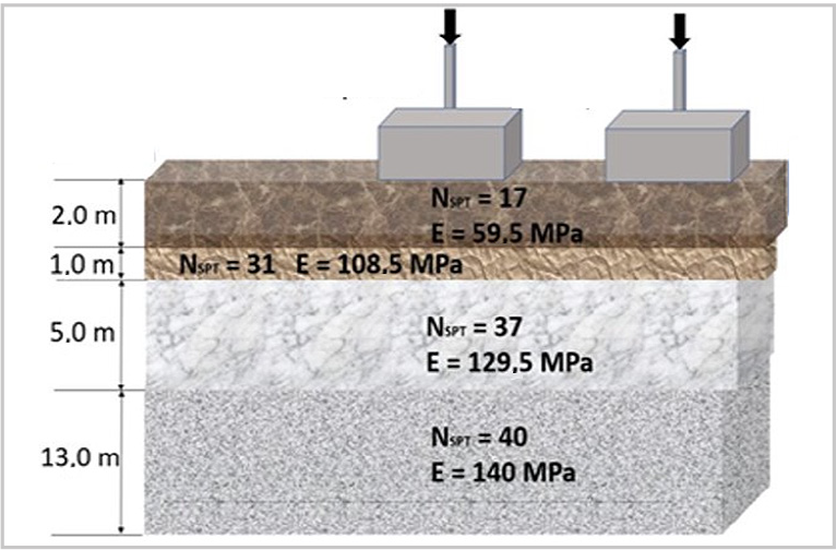
Figure 3 presents a soil profile of a 34-story residential building located in the Marista sector of Goiânia (Mundim; Cruvinel; Cavalcanti, 2014 and Sales, 2022). This profile was used for the validation of the stress propagation effect. The stratified soil profile is formed by 4 layers and has 3 spatially distributed footings. Note that the relationship between NSPT and the elastic modulus E is given in Equation 23.

Soil profile of a 34-story residential building located in the Marista sector of Goiânia: profile used to validate the interaction effect between three footings.
Figure 4 presents the model of part of the foundation of a 34-story building located in the Marista Sector, Goiânia (Mundim; Cruvinel; Cavalcanti, 2014). This model allows validating the implementations of both the deformation of the soil and the interaction between the supports, considering the effects of stress propagation. This figure shows the location elevations, dimensions and the Z depth of settlement. It should be noted that this example allows us to verify the program in a three-dimensional way, in view of the spatial distribution of the foundation.

The first case is an example of an isolated footing, in which the results obtained with the implemented program were 99.93% equal to the results in literature. The second model is part of a 34-story building located in the Marista sector, Goiânia (Mundim; Cruvinel; Cavalcanti, 2014). This case of the building allows us to validate the implemented program with regard to the propagation of stresses and interaction between the footings. As such, the effects were considered in the calculation of the reference. The comparison of the result of the implemented program with this building resulted in 97.17% of equality, as shown in Table 2.
Comparative analysis of the geotechnical implementation of the soil with results from the literature.
It is worth noting that it is possible to apply the methodology to other shallow foundations with different positions and depths than in this example; that is, the proposed methodology has the generality to automatically propagate shallow stresses in the different soil layers and consider the second-order effects between the stress propagations between the different foundations. Due to the internal use of a fundamental analytical solution to provide speed in the semi-numerical analysis, the geometry of the base of each foundation is limited to rectangular sections or compositions thereof. Future work may investigate the implementation for circular bases and propose approaches for generalized bases.
3.3 Verification of the soil-structure analysis
With the isolated functions checked, it is enough to check the internal consistency of the Soil-Structure Interaction loop to complete the verification of the implemented program. This validation is carried out by comparing the results obtained in the developed program, with the values calculated manually and externally using the Ftool program (Martha, 2022) and the geotechnical analysis function already validated with the examples in literature (Mundim; Cruvinel; Cavalcanti, 2014).
Figure 5 presents the structural model used for the verification of the iterative soil-structure loop. The material of the bars has a modulus of elasticity E = 25 x 106 kPa. The geometric properties are I = 5.1 x 10⁻⁵ m4 for the moment of inertia and A = 4.0 x10⁻² m2 for the cross-sectional area.

Structural model for verification of the iterative soil-structure loop.Source: Authors (2025).
For the verification of the ISE, the soil profiles presented in Figures 6 and 7 were considered. These figures show the thicknesses of the stratified soil and the level of discretization of the soil mass. The left support has a footing with dimensions 1.2 m x 1.3 m and the right support has dimensions 1.5 m x 1.5 m.


Table 3 presents the summary of the verification of the automatic internal implementation, with reference to the baseline results. RA0 and ρ0 refer, respectively, to the support reaction and the settlement, both in the initial case of non-displaceable supports. The terms RA1 and ρ1 refer to the case of the first iteration, considering deformable supports compatible with the calculated geotechnical settlement. RA2 and ρ2 refer to the values for the second iteration. It is noted that in the second iteration the result already converges, not suffering significant change between iterations.
4. Final considerations
The main objective of the research was consolidated and verified through the implementation of an efficient and low-cost computational solution for the analysis of lattice structures in an integrated way with the analysis of soil deformations. Through an iterative design internal to the program, this program allows several practical applications in civil structures, such as buildings with differential settlement (frame element), sheds, isolated floors (grid element) and any other structure that can be modeled as reticulated.
Among the functionalities of the implementation, we can mention the possibility of isolated analysis of the structure with spring support or settlement imposed on the non-displaceable support (see section 3.1). It is also possible to perform the analysis of settlement prediction isolated from the structure, considering the global effect of interaction between the stresses of the various support elements (see section 3.2). In the evaluation of settlements, it is possible to enter the geotechnical values for each support and consider the stratification of the soils (see Equation 20). In soil modeling, it is possible to control the level of discretization of each soil layer, inserting the number of sublayers in each layer of the stratified geotechnical profile (see Equation 20).
With this computer program completed, it is possible to carry out several practical applications and technical analyses of the behavior of structures in the deformed state of the ground, such as the evaluation of the sensitivity of buildings to the process of soil-structure interaction, as presented in the soil-structure interaction problem of section 3.3.
For future research, it is suggested to carry out Soil-Structure Interaction analyses with the implemented program. Parametric analyses of the soil type (soil strength) can be performed in the prediction of settlements by integrated soil-structure modeling in order to verify the dependence of the soil stiffness modulus to analyze the quantitative impact of the SSI for the structural design and the degree of influence by the number of floors.
In the geotechnical field, functions can be implemented for the evaluation of settlements in elements that jointly transmit normal and tangential stresses, such as piles and pile groups. There is also the possibility of implementing the evaluation of settlements in soft soils, considering densification and settlement over time. The plastic, drainage and dynamic loading effects with a semi-analytical approach still need to be investigated. In the structural scope, functions for nonlinear structural analysis can be implemented by the Positional Finite Element Method (Coda, 2018).
-
Funding information
Conselho Nacional de Desenvolvimento Científico e Tecnológico (National Council for Scientific and Technological Development) -(CNPq) - process 307868/2022-2.
Data availability
The authors state that this manuscript is based on the Monograph of Thiago Rodrigues Carvalho, entitled "IMPLEMENTAÇÃO MATRICIAL PARA ANÁLISE INTEGRADA SOLO-ESTRUTURA COM PROPAGAÇÃO DE TENSÕES" presented in 2022 at the Federal University of Goiás, in the Undergraduate Program in Civil Engineering (UFG), with all data available at the following link: https://eeca.ufg.br/p/21229-trabalhos-de-conclusao-de-curso-engenharia-civil.
References
- ALI, T.; ELDIN, M. N.; HAIDER, W. The effect of soil-structure interaction on the seismic response of structures using machine learning, finite element modeling and ASCE 7-16 methods. Sensors, v. 23, n. 4, p. 2047, 2023.
- ALMEIDA, G. C. Aplicação de conceitos de otimização ao projeto do edifício Kingdom Park Residence. 2021. 131 f. Trabalho de Conclusão de Curso (Graduação em Engenharia Civil) - Universidade Federal de Goiás, Goiânia, 2021.
- ALONSO, U. R. Exercícios de fundações. São Paulo: Edgard Blucher, 1943.
-
ALTO QI. Análise de esforços e deslocamentos. [S.l.], [s.d.]. Disponível em: https://altoqi.com.br/eberick Acesso em: 04 mar. 2022.
» https://altoqi.com.br/eberick -
ALTO QI. Como determinar o coeficiente de recalque vertical. 2022. Disponível em: https://suporte.altoqi.com.br/hc/pt-br/articles/115004184613-Como-determinar-o-coeficiente-de-recalque-vertical-. Acesso em: 26 ago. 2022.
» https://suporte.altoqi.com.br/hc/pt-br/articles/115004184613-Como-determinar-o-coeficiente-de-recalque-vertical - AMERICAN SOCIETY FOR TESTING AND MATERIALS. ASTM D4719-07: standard test methods for prebored pressuremeter testing in soils. West Conshohocken, 2007.
- AMERICAN SOCIETY FOR TESTING AND MATERIALS. ASTM D6635-15: standard test method for performing the flat plate dilatometer. West Conshohocken, 2015.
- ASSOCIAÇÃO BRASILEIRA DE NORMAS TÉCNICAS. ABNT NBR 6118: projeto de estruturas de concreto - procedimento. 3. ed. Rio de Janeiro, 2014.
- ASSOCIAÇÃO BRASILEIRA DE NORMAS TÉCNICAS. ABNT NBR 6484: solo - sondagem de simples reconhecimento com SPT - método de ensaio. Rio de Janeiro, 2020.
- BAGUELIN, F.; JEZEQUEL, J. F.; SHIELDS, D. H. The pressuremeter and foundation engineering. Trans Tech Publications. Series on Rock and Soil Mechanics, v. 2, n. 4. Germany, 1978.
- BAHIA, G. A. D.; CUNHA, R. P.; MOTA, N. M. B. Desempenho de edifícios altos com emprego da interação solo-estrutura. Campinas: Unicamp, 2021. v. 12.
- BITTENCOURT, M. L. Análise computacional de estruturas. Campinas: Unicamp, 2010.
- CARBONELL, J. M. et al. Geotechnical particle finite element method for modeling of soil-structure interaction under large deformation conditions. Journal of Rock Mechanics and Geotechnical Engineering, v. 14, n. 3, p. 967-983, 2022.
- CODA, H. B. O método dos elementos finitos posicional: sólidos e estruturas - não linearidade geométrica e dinâmica. São Carlos: EESC/USP, 2018.
- COLMEIA CONSULTORIA E PROJETO. Projeto estrutural Kingdom Park Residence. Goiânia, 2016.
- DHADSE, Gaurav D.; RAMTEKKAR, G. D.; BHATT, Govardhan. Finite element modeling of soil structure interaction system with interface: A review. Archives of Computational Methods in Engineering, v. 28, p. 3415-3432, 2021.
- DITZ, J. D. FSCalc: calculadora de seções de concreto armado sujeitas a flexão normal simples e cisalhamento. [S.l.]: TQS, 2022.
- FARIAS, R. S. Análise estrutural de edifícios de paredes de concreto com a incorporação da interação solo-estrutura e das ações evolutivas. 2018. 263 f. Tese (Doutorado em Engenharia de Estruturas) - Escola de Engenharia de São Carlos - Universidade de São Paulo, São Carlos, 2018.
- GERE, J. M.; WEAVER JR, W. Análise de estruturas reticuladas. Rio de Janeiro: Guanabara, 1981.
- GERE, J. M.; WEAVER JR, W. Matrix analysis of framed structures. 3. ed. New York: Van Nostrand Reinhold, 1990.
- IGLESIA, S. M. A interação solo-estrutura e sua aplicação na análise de estruturas de edifícios. [S.l.]: ALTO QI, 2022.
- INTERNATIONAL ORGANIZATION FOR STANDARDIZATION. ISO 22476-11: geotechnical investigation and testing - field testing - Part 11: flat dilatometer test. Geneva, 2017.
- LUAMBA, E. S. Formulação MEC/MEF para a análise da interação solo estratificado/estrutura e da estabilidade da estaca. 2022. 160 f. Tese (Doutorado em Engenharia de Estruturas) - Escola de Engenharia de São Carlos, Universidade de São Paulo, São Carlos, 2022.
- MARCHETTI, S. In situ tests by flat dilatometer. Journal of the Geotechnical Engineering Division, v. 106, n. 3, p. 299-321, 1980.
- MARTHA, L. F. Análise de estruturas: conceitos e métodos básicos. 2. ed. Rio de Janeiro: LTC, 2020.
- MARTHA, L. F. FTOOL: two-dimensional frame analysis tool. Rio de Janeiro: PUC-Rio, Departamento de Engenharia Civil, 2022.
- MONFORTE, L.; ARROYO, M.; CARBONELL, J. M.; GENS, A.. Coupled effective stress analysis of insertion problems in geotechnics with the Particle Finite Element Method. Computers and Geotechnics, v. 101, p. 114-129, 2018.
- MONFORTE, L.; ARROYO, M.; CARBONELL, J. M.; GENS, A. Numerical simulation of undrained insertion problems in geotechnical engineering with the Particle Finite Element Method (PFEM). Computers and Geotechnics, v. 82, p. 144-156, 2017.
- MORRISON, N. Interacción suelo-estructuras: semiespaço de Winkler. Barcelona: Universidad Politécnica de Cataluña, 1993.
- MUNDIM, D. P. R.; CRUVINEL, E.; CAVALCANTI, M. Implementação de uma ferramenta numérica para previsão de recalques em sapatas. 2014. 61 f. Trabalho de Conclusão de Curso (Graduação em Engenharia Civil) - Universidade Federal de Goiás, Goiânia, 2014.
- OUYANG, Weihang et al. Machine learning-based soil-structure interaction analysis of laterally loaded piles through physics-informed neural networks. Acta Geotechnica, v. 19, n. 7, p. 4765-4790, 2024.
- PINTO, C. S. Curso básico de mecânica dos solos. 3. ed. São Paulo: Oficina de Textos, 2006.
- RAMOS, A. P. F. Análise da interação estaca-solo-superestrutura com o acoplamento MEC-MEF. 2013. 193 f. Tese (Doutorado em Engenharia de Estruturas) - Escola de Engenharia de São Carlos, Universidade de São Paulo, São Carlos, 2013.
- RIBEIRO, I. S. et al. Análise linear elástica de pórticos espaciais. In: SIMPÓSIO DE MECÂNICA COMPUTACIONAL, 11.; ENCONTRO MINEIRO DE MODELAGEM COMPUTACIONAL, 2014, Juiz de Fora. Anais [...]. Juiz de Fora: SIMMEC/EMMCOMP, 2014.
- RUVER, C. A. Determinação do comportamento carga-recalque de sapatas em solos residuais a partir de ensaios SPT. 2005. Dissertação (Mestrado em Geotecnia) - Programa de Pós-Graduação em Engenharia Civil, Universidade Federal do Rio Grande do Sul, Porto Alegre, RS, 2005.
- SALES, M. M. Notas de fundações: recalques em sapatas sobre areias e argilas. Goiânia: Escola de Engenharia Civil e Ambiental, UFG, 2022.
- SCHNAID, F. Ensaios de campo e suas aplicações à engenharia de fundações. São Paulo, SP: Oficina de Textos, 2000. 189 p.
- SHRESTHA, A.; GUPTA, M.; GHANI, S. Evaluating seismic resilience of steel buildings: integrating soil-structure interaction and ensemble modeling approaches. Modeling Earth Systems and Environment, p. 1-26, 2024.
- SILVA, R. C. S. Análise da interação estaca inclinada e o solo via combinação MEC/MEF. 2020. 132 f. Dissertação (Mestrado em Engenharia Civil - Engenharia de Estruturas) - Escola de Engenharia de São Carlos, Universidade de São Paulo, São Carlos, 2020.
- SILVA, W. Q. Sobre análise não linear geométrica de edifícios considerando o empenamento dos núcleos estruturais e a interação solo-estrutura. 2014. 186 f. Tese (Doutorado em Engenharia de Estruturas) - Escola de Engenharia de São Carlos, Universidade de São Paulo, São Carlos, 2014.
- SORIANO, H. L. Análise de estruturas: formulação matricial e implementação computacional. Rio de Janeiro: Ciência Moderna, 2005.
- SOUZA, R. A.; REIS, J. H. C. Interação solo-estrutura para edifícios sobre fundações rasas. Acta Scientiarum - Technology, v. 30, n. 2, p. 161-171, 2008.
- STROUD, M. A. The standard penetration test - its application and interpretation. In: I.C.E. CONF. ON PENETRATION TESTING IN THE UK. Proceedings [...]. Londres: Thomas Telford, 1989.
- TAMAYO, J. L. P.; AWRUCH, A. M. On the validation of a numerical model for the analysis of soil-structure interaction problems. Latin American Journal of Solids and Structures, v. 13, n. 8, p. 1545-1575, 2016.
- TECGRAF. Linear elements structure model. Titular: Tecgraf/PUC-Rio. BR, 2017.
-
TQS. Análise estrutural com pórtico espacial completo. 2020. Disponível em: https://www.tqs.com.br/v16/destaques/modelo-vi-projeto-estrutural.html Acesso em: 01 abr. 2022.
» https://www.tqs.com.br/v16/destaques/modelo-vi-projeto-estrutural.html -
TQS. Apoios unilaterais. 2022. Disponível em: https://docs.tqs.com.br/Docs/Details?id=463523295&language=pt-BR Acesso em: 04 mar. 2022.
» https://docs.tqs.com.br/Docs/Details?id=463523295&language=pt-BR -
TQS. CRV - sapatas e tubulões. [S.l.], [s.d.]. Disponível em: https://docs.tqs.com.br/Docs/Details?id=3828&language=pt-br Acesso em: 27 ago. 2022.
» https://docs.tqs.com.br/Docs/Details?id=3828&language=pt-br - YAZDCHI, M.; KHALILI, N.; VALLIAPPAN, S. Dynamic soil-structure interaction analysis via coupled finite-element-boundary-element method. Soil Dynamics and Earthquake Engineering, v. 18, n. 7, p. 499-517, 1999.
Edited by
-
Associate Editor
Diogo Rodrigo Ferreira Ribeiro


 Source: Authors (2025).


 Source: Authors (2025).
 Source: Authors (2025).