Abstract
The management and monitoring of mechanized tunnel excavation parameters are crucial for ensuring the safety, quality and project's time/costs, since these parameters are the only existing elements that enable the evaluation of the performance of the excavation itself. In this study, will be presented the computational tool christened as SAPE (Support System and Monitoring of Underground Excavation Parameters), an innovative tool meant to assist the monitoring of ongoing or completed mechanized tunneling projects. The tool was designed to be a flexible and simple management tool, which means that it can be customized as a function of the characteristics of each project. The default version comprises the most important excavation parameters (a total of 14). Besides, it has important functions, such as geolocation (GoogleEarth program), historical production data and basic excavation statistics. The software was tested in the recently completed twin tunnels of the Subway Line 5 - Lilac in the city of São Paulo, Brazil.
Keywords:
mechanized tunnels; excavation parameters, geotechnical software; subway Line 5 -Lilac, São Paulo
1. Introduction
In the last years, an increase in the use of the underground space has occurred in Brazil, in particular, in the large and highly populated urban centers, where there is a high demand for urban mobility (Rocha, 2012ROCHA, H.C. Panorama do mercado brasileiro de túneis: passado, presente e futuro. In: CONGRESSO BRASILEIRO DO CONCRETO, 54. Anais... Maceió: IBRACON, 2012. p. 1-16.). An increasing number of transportation tunnels have been made by Tunnel Boring Machines (TBM), popularly known in the country as “tatuzões”. The main control process and follow up of this type of excavation is accomplished by analyzing altogether the parameters of operation of these machines, the geological and geotechnical ground conditions and the geotechnical monitoring data. During the excavation cycle, a large number of different parameters are recorded each 10 seconds (over 300), constituting a large database. Currently, the management of this data in the country is performed by using software solutions developed overseas. Commonly, these softwares are rent during construction and their prices depends, among other things, on the amount of functionalities needed. The machine data and processing tools for dealing with it are relatively simple. ACCESS or EXCEL softwares can be used for processing DBF files. However, it is a manual and time-consuming operation. For these reasons, developing a program for dealing with large databases in a flexible and rapid manner is justifiable. Before that, the purpose of this paper is to present an alternative solution capable of managing such large databases, both for ongoing or completed tunneling projects. The Support System and Monitoring of Underground Excavation Parameters - SAPE was developed and applied during the construction of the twin mechanized tubes of the Lot 3 of the Subway Line 5 - Lilac (São Paulo, Brazil), where the author provided consulting services. The development of the SAPE was driven due to the limitations found by the author in the version of the software provided by the Contractor Consortium (Andrade Gutierrez and Camargo Corrêa companies) to the engineers of the Companhia do Metropolitano de São Paulo - Metrô (CMSP) for the follow up of the excavations. The main limitations found in the version of the software provided by the contractor were: (1) few graphs of the excavation parameters were available; (2) it was not able to plot data in GoogleEarth; (3) several times renderization speed of machine data was not good enough; (4) users was not allowed to edit any graph (e.g. axis, titles, labels, etc.); (5) users was not allowed to check raw data (DBF files). In other words, check for bugs and other excavation parameters that could help understanding tunnelling performance; (6) any statistical coefficient was unavailable. When dealing with large data sets descriptive statistics can help to distinguish trends in a collection of information; and (7) it was not able to visualize ring production. A patent application for the program was deposited with the Instituto Nacional de Propriedade Industrial - INPI under the code BR 51 2016 000393 6.
2. Support system and monitoring of underground excavation parameters
There are today quite a few commercial software packages for the management of operational and performance machine parameters, such as PROCON, GDMS, TPC, etc. (Guglielmetti et al. 2008GUGLIELMETTI, V., GRASSO, P., MAHTAB, A., XU, SHULIN. Mechanized tunnelling in urban areas: design methodology and construction control. Balkema: Taylor & Francis, 2008. 507p.). Although all the abovementioned packages are able to deal with a great number of parameters and have many functionalities, such as connection with instrumentation data and mobile versions, all of them represent closed solutions. In Brazil, the literature is very scarce on this theme. This is probably due to the limited number of projects in which mechanized excavations were used (Celestino et al. 2006CELESTINO, T., KOSHIMA, A., TELLES, R.C.D., ASSIS, A. (Eds.). Túneis do Brasil. São Paulo: ABMS, 2006. 327p.).
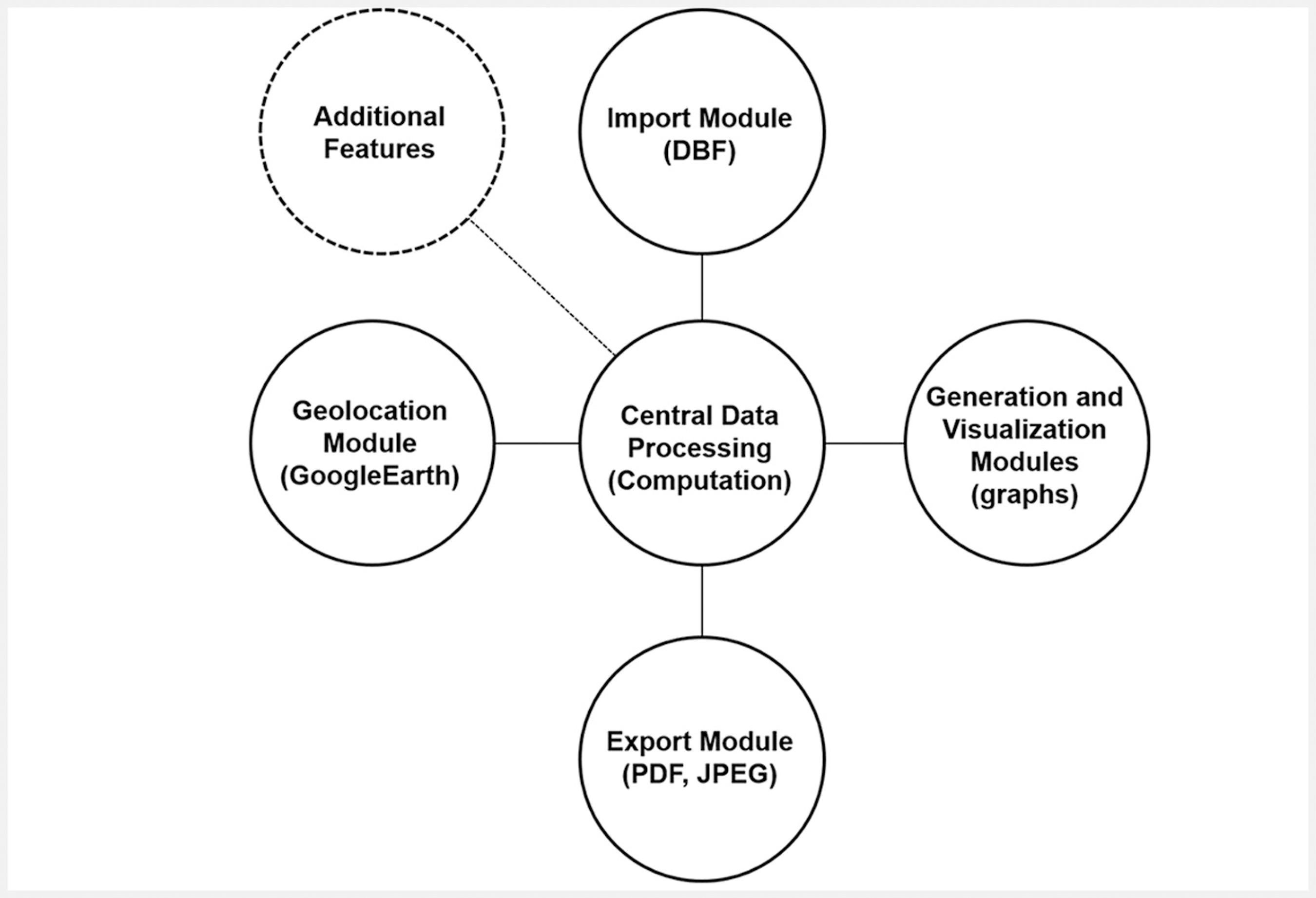
The software SAPE was developed in the programming language C#.NET for Desktop Windows. It was conceived as a modular software, scalable, which allows it to be easily updated or that new functionalities be appended at any time, as a function of the needs/characteristics of each project (Figure 1). The computer configuration needed for running SAPE is that .NET Framework 4.5.2 and Windows 7 (or higher versions) are installed on the computer. All the tests performed in the development of this project were done using a 2.1 GHz Celeron Dual Core and 2 GB of RAM memory. It is worth mentioning that performance also depends on the amount of files loaded.
Architecture of the software SAPE. “Additional Features” states for any other excavation parameter needed in order to better understand tunnel performance.
The software SAPE process DBF files (database file) and it is by all means a generator and viewer of graphics, specially designed to cope with the main parameters needed to follow up mechanized tunnels (by default a total of 14 parameters). In order to facilitate data analysis for users, the set of parameters were grouped into three distinct categories: (1) excavation; (2) soil conditioning; and (3) lining backfill system (Table 1). Details about the meaning of each parameter listed in Table 1 and its interpretation is provided in subsection 3.4. Readers are also encouraged to consult Guglielmetti et al., (2008)GUGLIELMETTI, V., GRASSO, P., MAHTAB, A., XU, SHULIN. Mechanized tunnelling in urban areas: design methodology and construction control. Balkema: Taylor & Francis, 2008. 507p. and Shirlaw (2016)SHIRLAW, N. Pressurised TBM tunnelling in mixed face conditions resulting from tropical weathering of igneous rock. Tunnelling and underground space technology, v. 57, p. 225-240, 2016.. The software allows the analyst to select the set of data, based on the date of the assembly of each ring or based on its code number (rings are labelled with sequential Arabic numbers). The software allows the complete edition of the graph as well as the exhibition of labels. In the legend of each graph, some statistical information is shown, such as the lowest value, the maximum value and the mean, which ultimately helps the identification of potential trends. The user has the option of exporting single graphs or a report containing all graphs as a PDF or a raster file (formats like tif, jpeg or png). In addition, in order to better control the volume of material excavated, which is crucial in tunnels excavated in urban areas, the SAPE allows one to export a spreadsheet containing all the raw data of the 14 parameters recorded by the machine. Parameters to evaluate mechanisms such as twist, roll and tilt of the TBM machine are usually controlled by contractors, and for this reason where not incorporated in the program.
List of key excavation parameters processed by the SAPE system. Legend: 1- excavation parameters, 2- parameters for the soil conditioning and 3- parameters for the lining backfill system.
In order to keep the performance of the software as reasonable as possible, it was established that for data sets larger than 10 DBF files, the software must provide only average values for each parameter. In case the user is interested in analyzing the full raw data to get a better picture of the data fluctuation, he must select a smaller set of files.
The software SAPE also allows the user to view the set of files loaded in a high resolution and updated satellite image in the GoogleEarth program. This capability allows the parameters of excavation to be correlated to other geocoded databases, such as geology, hydrogeology, environment, etc. Finally, the software also provides information about the tunnel production. The information is given per ring and summarized in a bar graph, comprising the time of excavation, the ring assembly duration and eventual standstills.
The Figure 2 presents SAPE main window, which is divided in four main regions: (A) data options and manipulation; (B) and (C) number of rings uploaded and chart features editing, respectively; and (D) chart visualisation. Each operation can be accessed through different buttons and options located in the application panel. Depending on the user needs, some buttons can be toggled between active and inactive states.
In short, SAPE is a software for the technical controlling of mechanized tunnels. It aims to visualize and manipulate excavation parameters in order to assist engineers and geologists in decision making during tunneling.
3. Study case: lot 3 of subway line 5-lilac
3.1 General aspects
The Subway Line 5 - Lilac is 20.8 km long and comprises 17 stations, located between Capão Redondo and Chácara Klabin neighborhoods, southern region of the São Paulo city. This line connects to the Line 1 - Blue (Santa Cruz Station), the Line 2 - Green (Chácara Klabin Station), the Line 9 - Emerald (Santo Amaro Station) and the Line 17-Gold (Campo Belo Station), all of them currently under construction. It is estimated that the daily demand will be 771 thousand people a day. From the 20.8 km planned, 9.6 km are already in operation (from Station Capão Redondo to Station Adolfo Pinheiro). The remaining stretch is divided in the lots 3 and 7.
Lot 3 of the Subway Line 5 - Lilac, focus of this article, comprises two twin tubes with 6.89 m in diameter and 5.3 km in length. The Lot 3 comprises four stations (Alto da Boa Vista, Borba Gato, Brooklin and Campo Belo) and seven emergency/ventilation shafts (VSE and VCA). The coverage over the tunnel crown varies between 15 to 25 meters. The highest topographic level occurs close to the São Sebastião Shaft (767 m.a.s.l) and the lowest point close to the Campo Belo Station (736 m.a.s.l). In order to minimize the influence of the excavation of the first tunnel (Via 1 - S789) over the second tunnel (Via 2 - S790), the machines have left the Conde de Itu Shaft towards the Bandeirantes Shaft with a time lag of a month. Lot 7 starts from the Bandeirantes Shaft towards the Chácara Klabin Station (Line 2 - Green) and comprises a single mechanized tunnel and six metro stations (Figure 3).
Sketch depicting the location of the Lot 3 of the Subway Line 5 - Lilac. For details, readers should refer to the text. The background image was taken from the GoogleEarth.
The tunnel lining is composed of conventional concrete rings reinforced with steel bars (A) and concrete rings reinforced with steel fibers (F). In addition, there were also tested two other types of concrete rings in Lot 3, not described here. The external diameter of the concrete rings is 6.6 meter. Its length equals to 1.5 meters and its thickness is 0.3 meters. The ring is composed of six universal segments (5 + 1) and has a frusto-conical shape. Each ring segment is equipped with water-stop joints made of neoprene bands. The segments are put together by means of metal screws during the ring assembly in the shield. Once the ring is assembled, the bands are compressed and groundwater flow into the tunnel is stopped.
3.2 Characteristics of the tunnel boring machines
The twin tunnels of Lot 3 were excavated by machines of the HERRENKNECHT brand, models S-789 and S-790. Table 2 summarizes the main characteristics of the machines designed for the project.
Main characteristics of the tunnel boring machines used in the excavation of the twin tunnels of the Lot 3 of the Subway Line 5 - Lilac.
3.3 Overview of the geological and geotechnical aspects
The geology of the tunnels of Lot 3 comprises Quaternary alluvial deposits, Tertiary fluvial-lacustrine sediments of the São Paulo and Resend formations, included in the São Paulo Sedimentary Basin and the geological-geotechnical units derived from the chemical weathering of the Precambrian basement gneisses (Riccomini et al., 2004RICCOMINI, C., SANT’ANA, L.G., FERRARI, A.L. Evolução geológica do Rift Continental do Sudeste do Brasil. In: MANTESSO-NETO et al. (Eds.). Geologia do Continente Sul-Americano: evolução da obra de Fernando Flávio Marques de Almeida. São Paulo: Becca. 2004. cap. XXIII, p. 383-406. 673p.; Monteiro et al., 2012MONTEIRO, M.D., GURGUEIRA, M.D., ROCHA, H.C. Geologia da região metropolitana de São Paulo. In: NEGRO et al. (Ed.). Twin Cities: solos das regiões metropolitanas de São Paulo e Curitiba. São Paulo: ABMS, 2012. cap. 1, p. 17-46. 508p.) (Figure 4). Due to the vertical topographic profile of the tunnels, the alluvial deposits were never mined and for this reason will not be described herein.
Simplified geological profile with indication of the metro stations of the Lot 3. Adapted with permission of the authors (Silva et al., 2015SILVA, M.A.A. P., AGUIAR, G., GONÇALVES, F.L. Twin tunnels excavated in sandy soils in a density urban area. In: PROCEEDINGS OF THE WORLD TUNNEL CONGRESS - WTC. 2015. Dubrovnik. Annals… Dubrovnik: ITA-AITES, 2015.). Legend: Yellow - Quaternary alluvium deposits, Orange - São Paulo Formation, Pale blue - Resende Formation and Green - Precambrian basement.
The São Paulo Formation is overlain by landfills and alluvial deposits and overlaps the Resend Formation, and it can reach up to 20 meters in thickness over the tunnel crown. The São Paulo Formation is constituted by over-consolidated reddish clayey sands, with SPT values ranging from 2 to 18 blows. It also shows levels of iron duricrusts, which control the groundwater flow. The Resende Formation comprises greenish to greyish over-consolidated sandy clays (also known as “Taguá”), presenting SPT values ranging from 20 to 48 blows. The distinction between the São Paulo and Resende formations based solely on the SPT values is not always very obvious, due to, among other things, the heterogeneity of the São Paulo Formation. The Resende Formation occurred mainly between Borba Gato Station and Roque Petrella Shaft and its thickness can reach locally up to 15 meters over the tunnel crown. The geological-geotechnical units derived from the chemical weathering of the Precambrian basement gneisses can be grouped into three main geotechnical units: residual soil, saprolite and weathered biotite gneiss. The residual soils are made of silty sand and silty clay, with SPT values ranging from 2 to 10. Residual soils also contain some amount of cobbles and geological structures inherited from parent rock. The saprolite term used here, corresponds to a weathered rock, impenetrable to the standardized SPT sampler. Usually, saprolite presents SPT values higher than 30 blows. The biotite gneisses are highly foliated and present steeply dipping NE-SW trending orientation. Futai et al., (2012)FUTAI, M.M., CECÍLIO JÚNIOR, M.O., ABRAMENTO, M. Resistência ao cisalhamento e deformabilidade de solos residuais da região metropolitana de São Paulo. In: NEGRO et al. (Ed.). Twin Cities: solos das regiões metropolitanas de São Paulo e Curitiba. São Paulo: ABMS, 2012. cap. 7, p. 155-187. 508p. have shown that these geological materials are very heterogeneous. Uniaxial compressive tests carried out in weathered gneiss showed that strength can easily vary from 5 to 60 MPa depending on the content of biotite bands. Recent studies presented by Monteiro and Rocha (2015)MONTEIRO, M.D., ROCHA, H.C. A experiência do Metrô de São Paulo nos estudos de abrasividade de rochas: técnicas para previsão do consumo de ferramentas de corte em escavações subterrâneas. Revista Engenharia, v. 625, p. 119-124, 2015. have revealed that the biotite gneisses also exhibit a very high CERCHAR abrasivity index.
Groundwater pressures monitored by tens of piezometers installed at different depths along the tunnel alignments have indicated that water pressure can reach up to 20 meters over the tunnel crown. In addition, slug tests carried on some of these piezometers installed in the São Paulo Formation have shown that its permeability ranges from 10-4 to 10-5 cm/s.
3.4 Managing of mechanized excavation parameters
Due to the large amount of data related to the excavation of the tunnels of the Lot 3 (total of 5,700 rings), presented herein will just be the results of the second tunnel (Via 1 - S790), in particular the results obtained in the stretch between Campo Belo Station (Jornalista Roberto Marinho Avenue) and the Jesuíno Maciel Shaft (Jesuíno Maciel Street). This stretch was selected due to the operational and technical challenges faced, which required the geotechnical treatment of the ground (cement and chemical injections from the surface), resulting in a much longer time to transpose it. More information about the excavation of this stretch can be found in Comulada et al., (2016)COMULADA, M., MAIDL, U., SILVA, M.A.A.P., AGUIAR, G., ARGIMIRO, A.F. Experiences gained in heterogeneous ground conditions at the twin tube EPB shield tunnels in Sao Paulo Metro Line 5. In: PROCEEDINGS OF THE WORLD TUNNEL CONGRESS - WTC, 2016. San Francisco. Annals… San Francisco: ITA-AITES, 2016. v. 1-4, p. 3208-3218. and Silva et al., (2016)SILVA, M.A.A.P., AGUIAR, G., ARGIMIRO, A.F., ROCHA, H.C., HARTWIG, M.E. Experience gained in the excavation of two parallel shields tunnels of 6.0 m for the São Paulo Metro. In: BRAZILIAN CONFERENCE ON SOIL MECHANICS AND GEOTECHNICAL ENGINEERING - COBRAMSEG, 18. Anais…Belo Horizonte: ABMS, 2016.. The stretch presents 556 m in length (371 rings | 2179-2549) and was predominantly mined in mixed face conditions - different proportions of residual soil, saprolite and weathered gneiss. The water table and the coverage over the tunnel crown varied from 10 to 20 meters and from 15 to 25 meters, respectively.
The parameters described herein are the same as presented in Item 2. The parameters are graphically interpreted by visual inspection with respect to the reference values (theoretical values) calculated by designers, estimated from the geometrical and geotechnical characteristics of the tunnel alignment, such as coverage, water table, geology, surface loads, etc. The graphs presented below were also compared to the graphs produced by the software provided by the contractor consortium to CMSP.
Figure 5 portrays two groups of parameters: soil conditioning and tunnel lining. The former, comprises the FIR (Foam Injection Ratio), FER (Foam Expansion Ratio) and Free-Water, and the last, the grout volume and the grout pressure. The parameters of soil conditioning have the purpose to control the consistency of the excavated material (also called as “muck”). The muck must be able to support the excavation face, to reduce the torque as well as the wearing of the cutting tools. These properties are achieved by injecting foam and water into the excavation face (and chamber) in the right proportion. The foam is a substance formed by air, water and detergent. The proportion among them must be accordingly controlled and is a function of the soil type and soil humidity in the excavation face. The FIR accounts for the proportion between the volume of foam injected and the volume of soil excavated. For cohesive soils, low values are usually employed. The FER represents the amount of air within the foam, and most of the time must be lower than 15. Therefore, the more air injected, the drier the foam becomes, which is indicated for granular soils. The free-water represents the volume (or the rate) of water injection within the excavation chamber. Normally, it is used for cohesive soils and mixed face (e.g. soil-rock) situations, increasing the homogenization of the muck and keeping its temperature as low as possible. According to Figure 5, the FER shows on average a value equal to 5.0 (humid foam) and the FIR shows on average a value of 100%, which is considered to be relatively high. The graph also shows that free-water was injected in most of the stretch (86 L/min). When both the FIR and the free-water present high values, there is a bigger risk of face instability, since the muck loses part of its consistency and it is not able to transfer enough pressure to the excavation face. The parameters of soil conditioning employed in this stretch are consistent with mixed face conditions. The grout volume injected in each ring was in general higher than the theoretical reference according to Figure 5. The reference value is calculated by subtracting the tunnel cross-section from the ring cross-section (external ring diameter) and multiplying the difference by the stroke length. Considering that the stroke length equals to 1.5 meter, the theoretical reference would equals to 4,600 L. The grout injection pressure allows one to evaluate if the grout could be spread on the external side of the rings (the annular gap between the tunnel diameter and the ring diameter). For this purpose, the pressure values of the upper lines of grout injection are compared with the uppermost earth pressure sensor (EP01). According to Figure 5, the adopted grout pressures were adequate. When both the pressure and the volume of grout are lower than the reference, high vertical settlements can be induced in the surface, affecting buildings, public facilities, etc. In the Lot 3, a bi-component grout injection system was used, having a liquid A (cement, water, clay and bentonite) and a liquid B (water-activated additive). After mixing the liquids, the grout becomes a jelly-like substance after a few seconds, reaching the strength of the surrounding soil few hours later.
Graphs showing the following parameters: (a) grout volume (L); (b) soil conditioning and (c) grout pressure for the upper grout lines of injection 1 and 6 (bar) for the stretch between Campo Belo Station and the Jesuíno Maciel Shaft (Via 1 - S790). In b, FER is a dimensionless number, FIR is expressed in percentage and free water expressed in L/min.
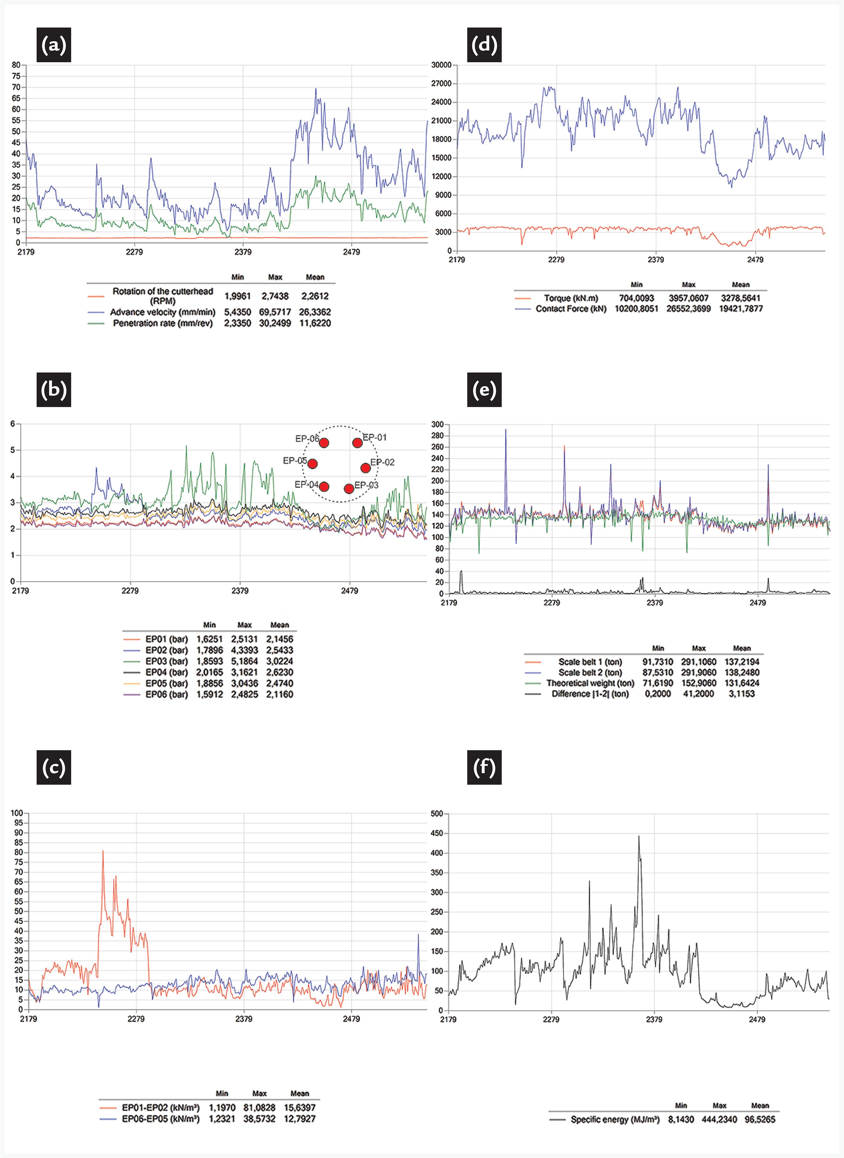
Figure 6 depicts the following graphs: advance speed, penetration rate, cutter head rotation, torque, contact force, earth support pressure, apparent density, specific energy and weight of the scale belts. The first three of them represent the performance of the excavation. The advance speed is obtained by multiplying the cutter head rotation by the penetration rate. The cutter head rotation is a function of the soil type in the excavation face. In mixed face conditions (soil-rock), for instance, it is recommended to use lower values (< 2.5 rpm) because of the high damaging potential to the cutting tools (breakage due to mechanical impacts). In general, advance speed should remain as constant as possible because the operator must immediately synchronize other excavation parameters, such as the screw conveyor speed, foam injection and grout injection rates, which affects the soil conditioning as well as the tunnel lining. In mixed face, the advance speed can vary significantly because of the proportion of soil and rock in the excavation face. These contrasting geological materials offer very different mechanical strengths to the machine advance. The graphs in Figure 6 show that the average values of the cutter head rotation were steady and around 2.2 rpm, while the average values of the penetration rate and the advance speed were equal to 11.6 mm/rev and 26 mm/rev, respectively. In the ring number 2430, the advance speed has increased abruptly, while the cutter head rotation remained constant. This indicates that the geological materials offered less resistance to the machine advance. The analysis of the parameters “contact force” and “specific energy” lead to the same conclusion. The former represents the force transferred to the face of the excavation, which is limited by the load capacity of the disk cutters. The last represents the average energy consumption per unit of excavated material. Both of them show a sudden decrease in the ring number 2430. The torque represents the force needed to rotate the cutter head around its axis. In general, cohesive soils require higher torque values. This parameter depends on the machine characteristics (e.g. nominal torque), which varies as a function of the tunnel diameter and the geological profile. As shown in Figure 6, the torque remained approximately constant and slightly below the reference (Table 1), with an average value of 3,280 kN.m. The earth support pressure represents the force necessary to balance the loads exerted by the soil and water columns over the tunnel face. In order to measure this parameter, pressure sensors are installed at different heights in the excavation chamber (Figure 6b). The apparent density is a measure of the “degree of filling of the chamber”. As a rule of the thumb, it must be as close as possible to 14 kN/m3, which ensures that the applied earth pressure is able to balance the ground loads.
Graphs showing the following parameters: (a) cutter head rotation (RPM)/advance velocity (mm/min)/penetration rate (mm/rev); (b) earth support pressure (bar); (c) apparent density (kN/m3); (d) torque (kN.m)/contact force (kN); (e) scale belts (ton); and (f) specific energy (MJ/m3) for the stretch between the Campo Belo Station and the Jesuíno Maciel Shaft (Via 1 - S790).
If the earth pressure and the apparent density are insufficient, large surface vertical settlements are expected. In some cases, it can even induce the failure of the excavation face. Figure 6b reveals a slight increase of the earth pressure values (measured by all the six sensors of pressure) followed by a progressive decrease, which is expected according to the longitudinal topographic profile (coverage). The apparent density shows in general adequate values. The pairs of sensors EP01-EP02 and EP06-EP05 are commonly used because the cutter head is free to rotate both to the right and to the left, affecting the pressures of the sensors installed in both sides of the cutter head. Finally, the weight measured by the scale belts is the unique parameter able to provide a real time detection of potential over excavations. Serious problems on the surface can be generated when this parameter is not well understood. Therefore, the control of it is made by comparing the real soil weight with the theoretical soil weight, which is determined by the specific weight of the soil. As shown in Figure 6e, the real weight was higher than the theoretical weight until ring number 2430, revealing potential over excavations and consequently, the necessity of ground treatment. Treatment of the ground was performed from the surface immediately after the detection of over excavations. More information about it can be found in Silva et al., (2016)SILVA, M.A.A.P., AGUIAR, G., ARGIMIRO, A.F., ROCHA, H.C., HARTWIG, M.E. Experience gained in the excavation of two parallel shields tunnels of 6.0 m for the São Paulo Metro. In: BRAZILIAN CONFERENCE ON SOIL MECHANICS AND GEOTECHNICAL ENGINEERING - COBRAMSEG, 18. Anais…Belo Horizonte: ABMS, 2016..
Although soil properties such as cohesion, shear strength, plasticity, permeability, deformability, and abrasiviness, control settlement behaviour and tunnelling performance, only soil weight is continuosly measured during tunnel drive. In order to avoid large settlements, parameters such as earth pressure, excavated soil weight and backfilling of the tail void must be well calibrated and monitored. It is worth mentioning that recent advances have been achieved in order to predict soil mechanical behavior by using inverse analysis of face pressure and soil loss (Zhao et al. 2015ZHAO, C., LAVASAN, A.A., BARCIAGA, T., ZAREV, V., DATCHEVA, M., SCHANZ, T. Model validation and calibration via back analysis for mechanized tunnel simulations - The Western Scheldt tunnel case. Computers and Geotechnics, v. 69, p. 601-614, 2015.). Moreover, tunnel boring machines with earth pressure support (EPB-TBM) can be operated in three basic modes depending on the predicted geological-geotechnical condition of the ground (Maidl, 2012MAIDL, U. Earth pressure balance Shields. In: MAIDL, B. et al. (Eds.). Mechanised shield tunnelling. Berlin: Ernst & Sohn, 2012. cap. 11, 255-289 p. 470p.). The mode of operation can also induce settlements and even soil failure. The closed mode is adopted when the soil at the tunnel face is not self-supporting and the tunnel is below the water table (incohesive soils). The stabilization of the ground is performed by pressurizing the excavated ground. In the closed mode, the excavation chamber is fully filled with excavated soil. In the transition mode the soil at the tunnel face is supposed to be self-supporting and water inflow can be handled by applying very low confinement pressures. In the transition mode the excavation chamber is partly filled with excavated soil. Finally, the open mode, is only adopted when the soil at the tunnel face is self-supporting and water inflow is not an issue (cohesive soils). For long urban tunnels such as the twin tunnels of Lot 3 in São Paulo city, the abovementioned operation modes were used interchangeably.
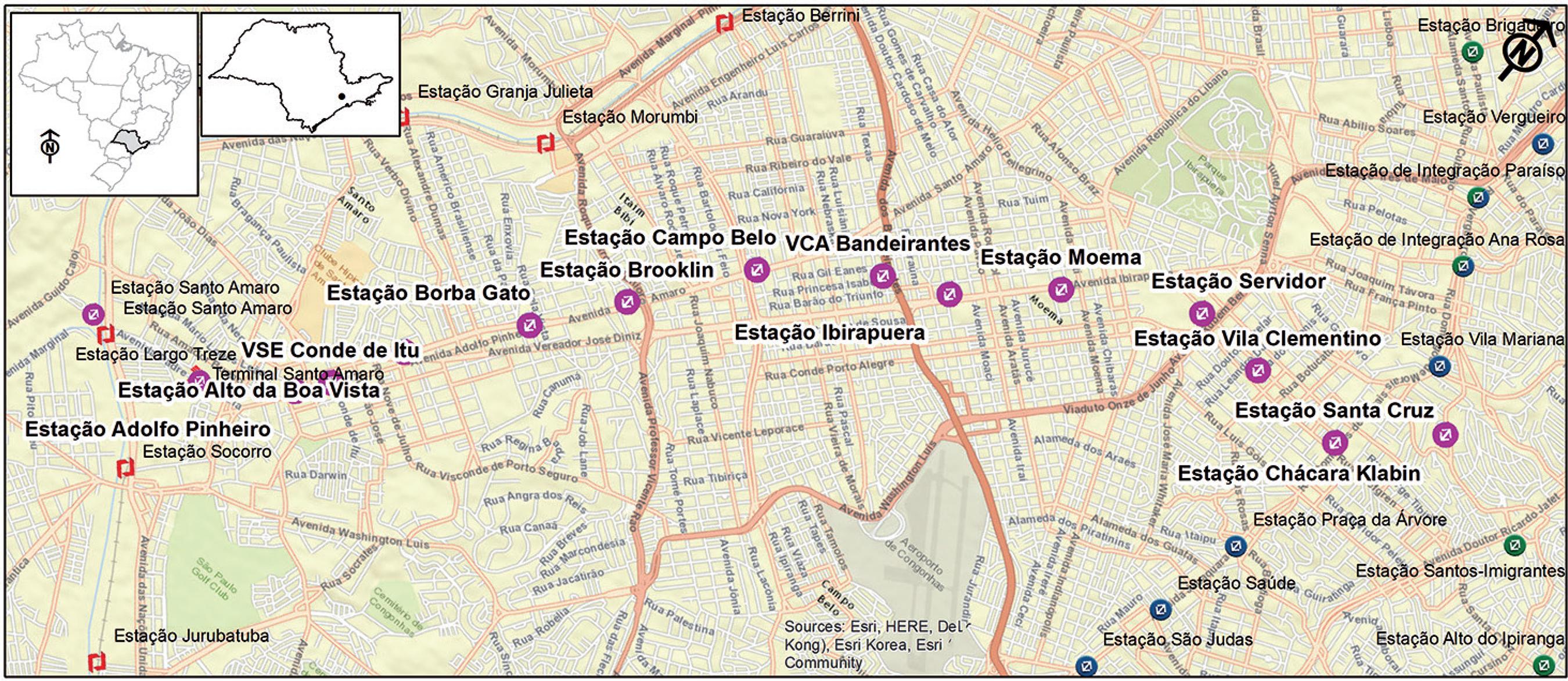
As mentioned in Item 2, the software SAPE also allows the geolocation of excavation data. Figure 7 portrays the set of rings described previously overlaid in a high resolution satellite image from the GoogleEarth acquired at 08-24-2012. The figure reveals that the Campo Belo Station, located close to the Jornalista Roberto Marinho Avenue (lower left | ring 2179) did not exist at that time. The possibility of exporting excavation data to GoogleEarth presents many advantages. For example, it allows the monitoring of the real time shield position in an updated base map, since highly urbanized regions are very dynamic in nature and present constant superficial changes. Moreover, geotechnical instrumentation drawings are usually prepared few years before the tunnel’s construction and for this reason they are commonly outdated. Additionally, there is also the possibility of combining information from many different sources, such as geology, surface deformation data, interferences, drillings, hydrogeology, contaminant plumes, etc., in a common geographic database. After construction, during tunnel operation, further investigation, such as geotechnical/structural monitoring and subsurface exploration, may be necessary. In this sense, it may assist the planning and management of these activities. Lastly, the surface impact of tunneling may lead eventually to compensation claims. The monitoring of the tunnel evolution through satellite scenes acquired over tens of months combined with excavation and geotechnical data can support decision makers.
Geolocation of the set of rings between the Campo Belo Station and the VSE Jesuíno Maciel (Via 1 - S790). Codes refer to the ring number. Background image from GoogleEarth (08-24-2012).
4. Final remarks and outlook
The goal of the SAPE program is to assist in the management of mechanized excavation parameters for tunnels. The program was successfully tested in the twin tubes of the Lot 3 of the Subway Line 5 - Lilac (in São Paulo city) and showed to be stable and reliable, and represents an alternative to other existing solutions. The program allows users to analyze in a fast, easy and straightforward way the main parameters associated to mechanized tunneling (a total of 14), supporting the quality, safety and performance evaluation of the excavation. The system was designed to be a flexible and simple managing tool, which means that it can be easily customized as a function of the characteristics of each project. Although there are today quite a few types of machines and manufactures worldwide, the database recorded has a similar structure (DBF files).
Recent research advances have been made lately in order to predict soil mechanical behavior by using inverse analysis of machine excavation parameters coupled with ground settlement field data. Such achievements may be extremely helpful in the future for an online estimation of key soil parameters.
Acknowledgements
The authors thank the Companhia do Metropolitano de São Paulo (Metrô), in the names of Luís Bastos (Contract Manager), Arlindo José Giampá (Chief of the Department of Civil Works), Jorge Yamashita (Technical Advisor), Argimiro Alvarez Ferreira (Technical Advisor), Hugo Cássio Rocha (Technical Advisor) and Jessé José dos Santos (Coordinator of Civil Works - Tunnels) for their support, valuable suggestions and for providing data. The authors also thank the Contractors (Consortium Andrade Gutierrez and Camargo Corrêa), in the name of Marco Aurélio Abreu Peixoto da Silva (Project Coordinator).
The authors would like to express his sincere thanks for the invaluable suggestions provided by the reviewers.
References
- CELESTINO, T., KOSHIMA, A., TELLES, R.C.D., ASSIS, A. (Eds.). Túneis do Brasil São Paulo: ABMS, 2006. 327p.
- COMULADA, M., MAIDL, U., SILVA, M.A.A.P., AGUIAR, G., ARGIMIRO, A.F. Experiences gained in heterogeneous ground conditions at the twin tube EPB shield tunnels in Sao Paulo Metro Line 5. In: PROCEEDINGS OF THE WORLD TUNNEL CONGRESS - WTC, 2016. San Francisco. Annals… San Francisco: ITA-AITES, 2016. v. 1-4, p. 3208-3218.
- FUTAI, M.M., CECÍLIO JÚNIOR, M.O., ABRAMENTO, M. Resistência ao cisalhamento e deformabilidade de solos residuais da região metropolitana de São Paulo. In: NEGRO et al. (Ed.). Twin Cities: solos das regiões metropolitanas de São Paulo e Curitiba São Paulo: ABMS, 2012. cap. 7, p. 155-187. 508p.
- GUGLIELMETTI, V., GRASSO, P., MAHTAB, A., XU, SHULIN. Mechanized tunnelling in urban areas: design methodology and construction control Balkema: Taylor & Francis, 2008. 507p.
- MAIDL, U. Earth pressure balance Shields. In: MAIDL, B. et al. (Eds.). Mechanised shield tunnelling Berlin: Ernst & Sohn, 2012. cap. 11, 255-289 p. 470p.
- MONTEIRO, M.D., ROCHA, H.C. A experiência do Metrô de São Paulo nos estudos de abrasividade de rochas: técnicas para previsão do consumo de ferramentas de corte em escavações subterrâneas. Revista Engenharia, v. 625, p. 119-124, 2015.
- MONTEIRO, M.D., GURGUEIRA, M.D., ROCHA, H.C. Geologia da região metropolitana de São Paulo. In: NEGRO et al. (Ed.). Twin Cities: solos das regiões metropolitanas de São Paulo e Curitiba São Paulo: ABMS, 2012. cap. 1, p. 17-46. 508p.
- RICCOMINI, C., SANT’ANA, L.G., FERRARI, A.L. Evolução geológica do Rift Continental do Sudeste do Brasil. In: MANTESSO-NETO et al. (Eds.). Geologia do Continente Sul-Americano: evolução da obra de Fernando Flávio Marques de Almeida São Paulo: Becca. 2004. cap. XXIII, p. 383-406. 673p.
- ROCHA, H.C. Panorama do mercado brasileiro de túneis: passado, presente e futuro. In: CONGRESSO BRASILEIRO DO CONCRETO, 54. Anais... Maceió: IBRACON, 2012. p. 1-16.
- SHIRLAW, N. Pressurised TBM tunnelling in mixed face conditions resulting from tropical weathering of igneous rock. Tunnelling and underground space technology, v. 57, p. 225-240, 2016.
- SILVA, M.A.A.P., AGUIAR, G., ARGIMIRO, A.F., ROCHA, H.C., HARTWIG, M.E. Experience gained in the excavation of two parallel shields tunnels of 6.0 m for the São Paulo Metro. In: BRAZILIAN CONFERENCE ON SOIL MECHANICS AND GEOTECHNICAL ENGINEERING - COBRAMSEG, 18. Anais…Belo Horizonte: ABMS, 2016.
- SILVA, M.A.A. P., AGUIAR, G., GONÇALVES, F.L. Twin tunnels excavated in sandy soils in a density urban area. In: PROCEEDINGS OF THE WORLD TUNNEL CONGRESS - WTC. 2015. Dubrovnik. Annals… Dubrovnik: ITA-AITES, 2015.
- ZHAO, C., LAVASAN, A.A., BARCIAGA, T., ZAREV, V., DATCHEVA, M., SCHANZ, T. Model validation and calibration via back analysis for mechanized tunnel simulations - The Western Scheldt tunnel case. Computers and Geotechnics, v. 69, p. 601-614, 2015.
Publication Dates
-
Publication in this collection
Oct-Dec 2018
History
-
Received
10 Feb 2018 -
Accepted
16 June 2018